TXTGTC400CThermal Camera
Robert Bosch Tool Corporation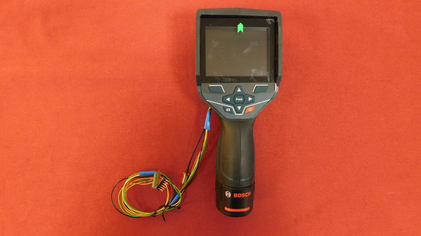
Click to zoom
Application Details
- Equipment Class
- DTS - Digital Transmission System
- Date of Grant
- Jul 10, 2022
- Application Purpose
- Original Equipment
- Date of Application
- Jul 10, 2022
- Equipment Note
- Thermal Camera
- Frequency Range
- 2412.00000000 - 2462.00000000
- Country
- United States
Documents & Files
Document Text
Text extracted from the exhibit documents filed with the FCC. Open a document above to read the original.
Users Manual
IMPORTANT: IMPORTANT : IMPORTANTE: Read Before Using Lire avant usage Leer antes de usar Operating/Safety Instructions Consignes de fonctionnement/sécurité Instrucciones de funcionamiento y seguridad GTC 400 C 1-877-BOSCH99 (1-877-267-2499) www.boschtools.com Call Toll Free for Consumer Information & Service Locations Pour obtenir des informations et les adresses de nos centres de service après-vente, appelez ce numéro gratuit Llame gratis para obtener información para el consumidor y ubicaciones de servicio For English Version Version française Versión en español See page 4 Voir page 19 Ver la página 34 2610057116 GTC400C 202206.indd 16/10/22 7:24 AM -2- XX.X° C XX.X°C XX.X° C XX .X°C XX .X°C XX .XX .X X XX X X.XX p m XX.X Mo de Ti tle XX.X° C XX.X°C XX.X° C XX .X°C XX .X°C XX .XX .X X XX X X.X X pm XX.X Mo de Title XX.X°C XX.X°C XX.X°C XX.X°C XX.X°C XX.XX.XXXX XX.XX pm XX.X Mode Title 12 3 4 5 13 12 11 14 15 16 17 20 10 19 18 7 6 8 9 abcde f h kjilm g GTC 400 C 2610057116 GTC400C 202206.indd 26/10/22 7:24 AM -3- BAT414 - BAT420 GBA12V30 GBA12V60 BC330 BC430 GAL 12V-20 21 22 1 600 A00 86E 2610057116 GTC400C 202206.indd 36/10/22 7:24 AM -4- Safety Symbols The definitions below describe the level of severity for each signal word. Please read the manual and pay attention to these symbols. This is the safety alert symbol. It is used to alert you to potential personal injury hazards. Obey all safety messages that follow this symbol to avoid possible injury or death. Read manual symbol - Alerts user to read manual. WARNING indicates a hazardous situation which, if not avoided, could result in death or serious injury. This symbol designates that this thermal camera tool complies with Part 15 of the FCC Rules. Use and care Use the correct tool for your application. The correct tool will do the job better and safer. Protect the tool, particularly the area around the camera and infrared lens, against moisture and snow. The reception lens could fog up and distort the measurements. Incorrect settings on the tool and other atmospheric influences may make the measurements inaccurate. Objects could be depicted hotter or colder, which may present a danger if touched. High temperature differences in a thermal image may cause even high temperatures to be shown in a colour associated with low temperatures. Coming into contact with such an area may cause burns. Temperature measurements will only be correct if the emissivity setting and the emissivity of the object match. Objects could be depicted hotter or colder in temperature and/or colour, which may present a danger if touched. Do not use the tool if the switch does not turn it on and off. Any tool that cannot be controlled with the switch is dangerous and must be repaired. Store idle tool out of the reach of children and do not allow persons unfamiliar with the tool or these instructions to operate the tool. Tools are dangerous in the hands of untrained users. Maintain tools. Check for misalignment or binding of moving parts, breakage of parts and any other condition that may affect the operation. If damaged, tool repaired before use. Many accidents are caused by poorly maintained tools. Use the tool, accessories, etc., in accordance with these instructions and in the manner intended for the particular type of tool, taking into account the working conditions and the work to be performed. Use of the tool for operations different from those intended could result in a hazardous situation. General Safety Rules Read all safety warnings, instructions, illustrations and specifications provided with this tool. Failure to follow all instructions listed below may result in electric shock, fire and/or serious injury. SAVE ALL WARNINGS AND INSTRUCTIONS FOR FUTURE REFERENCE The term “tool” in the warnings refers to your mains-operated (corded) tool or battery-operated (cordless) tool. 2610057116 GTC400C 202206.indd 46/10/22 7:24 AM -5- Battery tool use and care Recharge only with the charger specified by the manufacturer. A charger that is suitable for one type of battery pack may create a risk of fire when used with another battery pack. Use tool only with specifically designated battery packs. Use of any other battery packs may create a risk of injury and fire. When battery pack is not in use, keep it away from other metal objects like paper clips, coins, keys, nails, screws, or other small metal objects that can make a connection from one terminal to another. Shorting the battery terminals together may cause burns or a fire. Under abusive conditions, liquid may be ejected from the battery; avoid contact. If contact accidentally occurs, flush with water. If liquid contacts eyes, additionally seek medical help. Liquid ejected from the battery may cause irritation or burns. Do not use a battery pack or tool that is damaged or modified. Damaged or modified batteries may exhibit unpredictable behaviour resulting in fire, EXPLOSION or risk of injury. Do not expose a battery pack or tool to fire or excessive temperature. Exposure to fire or temperature above 265 °F (130 °C) may cause explosion. Follow all charging instructions and do not charge the battery pack or tool outside the temperature range specified in the instructions. Charging improperly or at temperatures outside the specified range may damage the BATTERY and increase the risk of fire. Disconnect the battery pack from the tool before making any adjustments, changing accessories, or storing the tool. Such preventive safety measures reduce the risk of starting the tool accidentally. Do not modify or attempt to repair the tool or the battery pack except as indicated in the instructions for use and care. Service Have your tool serviced by a qualified repair person using only identical replacement parts. This will ensure that the safety of the tool is maintained. Develop a periodic maintenance schedule for tool. When cleaning a tool be careful not to disassemble any portion of the tool since internal wires may b…
Text truncated - open the document above for the full version.
Cover Letter(s)
Spec Sheet http://www.ty-top.com The data i s reference only. Electrical c haracteristics vary depending on environment or measurement condition. TAIYO YUDEN reserves t he right t o make change to the data at any t ime without notice. Before making final s election, please check product specification. Chip Antennas(Multilayer) AH316M245001-T Features Item Summary MonoPole, 3.2x1.6x0.5mm, for Bluetooth/W-LAN/ZigBee Lifecycle Stage Mass Production (Preferred) Standard packaging quantity (minimum) Taping Embossed 3000pcs Products characteristics table SystemBluetooth/W-LAN/ZigBee Frequency Band Width2400 to 2500 MHz Center Frequency2450 MHz Gain1 (Peak Gain)(typ)+1.6 dBi Gain2 (Ave. Gain at OMNI plane)-0.1 dBi Efficiency (typ)-1.4 dB (72 %) VSWR (typ)3 TypeMonoPole Operating Temp. Range-40 to +85 °C RoHS Compliance (10 subst.)Yes REACH Compliance (209 subst.)Yes Halogen FreeYes SolderingReflow External Dimensions Dimension L3.2 ±0.15 mm Dimension W1.6 ±0.15 mm Dimension T0.5 ±0.1 mm Dimension E0.5 ±0.2 mm Dimension bMin 1.0 mm 2021.03.29 Powered by TCPDF (www.tcpdf.org) 1 / 1 ■ Notice for TA I YO YUDEN Products Please read this notice before using the TA I YO YUDEN products. ■ Please conduct validation and verification of our products in actual condition of mounting and operating environment before using our products. ■ The product listed in this spec sheet is intended for use in general electronic equipment (e.g., AV equipment, OA equipment, home electric appliances, office equipment, information and communication equipment including, without limitation, mobile phone, and PC). Please be sure to contact TA I YO YUDEN for further information before using the products for any equipment which may directly cause loss of human life or bodily injury (e.g., transportation equipment including, without limitation, automotive powertrain control system, train control system, and ship control system, traffic signal equipment, disaster prevention equipment, medical equipment classified as Class I, II or III by IMDRF, highly public information network equipment including, without limitation, telephone exchange, and base station). Please do not incorporate our products into any equipment requiring high levels of safety and/or reliability (e.g., aerospace equipment, aviation equipment, medical equipment classified as Class IV by IMDRF, nuclear control equipment, undersea equipment, military equipment). When our products are used even for high safety and/or reliability‐required devices or circuits of general electronic equipment, it is strongly recommended to perform a thorough safety evaluation prior to use of our products and to install a protection circuit as necessary. Please note that unless you obtain prior written consent of TA I YO YUDEN, TA I YO YUDEN shall not be in any way responsible for any damages incurred by you or third parties arising from use of the product listed in this spec sheet for any equipment requiring inquiry to TA I YO YUDEN or prohibited for use by TA I YO YUDEN as described above. ■ Information contained in this spec sheet is intended to convey examples of typical performances and/or applications of our products and is not intended to make any warranty with respect to the intellectual property rights or any other related rights of TA I YO YUDEN or any third parties nor grant any license under such rights. ■ Please note that the scope of warranty for our products is limited to the delivered our products themselves and TA I YO YUDEN shall not be in any way responsible for any damages resulting from a fault or defect in our products. Notwithstanding the foregoing, if there is a written agreement (e.g., supply and purchase agreement, quality assurance agreement) signed by TA I YO YUDEN and your company, TA I YO YUDEN will warrant our products in accordance with such agreement. ■ The contents of this spec sheet are applicable to our products which are purchased from our sales offices or authorized distributors (hereinafter “TAIYO YUDEN’s official sales channel”). Please note that the contents of this spec sheet are not applicable to our products purchased from any seller other than TA I YO YUDEN’s official sales channel. ■ Caution for Export The product listed in this spec sheet may require specific procedures for export according to “U.S. Export Administration Regulations”, “Foreign Exchange and Foreign Trade Control Law” of Japan, and other applicable regulations. Should you have any questions on this matter, please contact our sales staff. ! REMINDERS
Cover Letter(s)
are Trademarks of Robert Bosch GmbH, Germany Robert Bosch Tool Corporation 1800 W. Central Rd. Mount Prospect, IL 60056 www.bosch.us Gerard Pasciak, PT/ESS2-NA Tel +1 224 232-2382, Fax +1 224 232-2984 [email protected] Letter of Agency To Whom It May Concern, We certify that we are not subject to denial of federal benefits, that includes FCC benefits, pursuant to Section 5301 of the Anti-Drug Abuse ACT of 1988, U.S.C. 862. Further, no party, as defined in 47 CFR 1.2002(b), to the application, is subject to denial of federal benefits, that includes FCC benefits. Thank you for your attention to this matter. Yours sincerely Gerard Pasciak Approvals Engineer Element Materials Technology 100 Frobisher Business Park Malvern Worcestershire WR14 1BX UK February 01, 2022
Cover Letter(s)
are Trademarks of Robert Bosch GmbH, Germany Robert Bosch Tool Corporation 1800 W. Central Rd. Mount Prospect, IL 60056 www.bosch.us Gerard Pasciak, PT/ESS2-NA Tel +1 224 232-2382, Fax +1 224 232-2984 [email protected] Re: Request for confidentiality FCC ID: TXTGTC400C To Whom It May Concern, We hereby respectfully request that under the provision of 47 CFR 0.459 and 0.457(d) the documents listed below and attached with this application for certification be provided with confidential status. • Schematics • Operational Description • Block Diagrams • PCB Layout • Parts List Any exhibit / information for which we have requested confidentiality, but which may not be accorded such treatment by the FCC, should be returned to us. The documents listed above contain trade secrets that are treated as confidential by us. Substantial competitive harm to us could result should they be made available to the public. Federal Communications Commission Authorization and Evaluation Division 7435 Oakland Mills Road Columbia, Maryland 21046 February 01, 2022 February 01, 2022 Page 2 of 2 Yours sincerely Gerard Pasciak Approvals Engineer
Cover Letter(s)
are Trademarks of Robert Bosch GmbH, Germany Robert Bosch Tool Corporation 1800 W. Central Rd. Mount Prospect, IL 60056 www.bosch.us Gerard Pasciak, PT/ESS2-NA Tel +1 224 232-2382, Fax +1 224 232-2984 [email protected] AUTHORIZATION LETTER To Whom It May Concern As the listed company contact on the FCC database, I hereby authorize Christian Kiermeier to act on my behalf, in the following matters related to the FCC and IC approval of our Bosch model GTC400C Thermal Camera: report submittal, related correspondence, the signing of all documents relating to these matters, and any other lawful activity necessary to obtain such certification. Any act carried out by Christian Kiermeier within the scope of this authorization shall have the same effects as my own. This authorization shall expire one year from original date Yours sincerely Gerard Pasciak Approvals Engineer April 13, 2022
External Photos
210519-AU01+W01 Page 1 of 5 1 Annex B – EUT pictures external 1.1 List of Pictures Picture 1: EUT – top view ................................................................................................................................... 2 Picture 2: EUT – rear view.................................................................................................................................. 2 Picture 3: EUT – left side .................................................................................................................................... 3 Picture 4: EUT - right side .................................................................................................................................. 3 Picture 5: EUT – top side .................................................................................................................................... 4 Picture 6: EUT – bottom side without rechargeable battery ............................................................................... 4 Picture 7: Name plate of EUT without FCC-ID and IC-ID .................................................................................. 5 Picture 8: Name plate of EUT with FCC-ID and IC-ID ....................................................................................... 5 210519-AU01+W01 Page 2 of 5 Picture 1: EUT – top view Picture 2: EUT – rear view 210519-AU01+W01 Page 3 of 5 Picture 3: EUT – left side Picture 4: EUT - right side 210519-AU01+W01 Page 4 of 5 Picture 5: EUT – top side Picture 6: EUT – bottom side without rechargeable battery 210519-AU01+W01 Page 5 of 5 Picture 7: Name plate of EUT without FCC-ID and IC-ID Picture 8: Name plate of EUT with FCC-ID and IC-ID
ID Label/Location Info
Label & Location Document Label GTC400C Label placed on EUT
Internal Photos
210519-AU01+W01 Page 1 of 5 1 Annex C – EUT pictures internal 1.1 List of Pictures Picture 1: Opened EUT ...................................................................................................................................... 2 Picture 2: Right side of the EUT ......................................................................................................................... 2 Picture 3: Left side of the EUT ........................................................................................................................... 3 Picture 4: Opened EUT with module .................................................................................................................. 3 Picture 5: Top view of module ............................................................................................................................ 4 Picture 6: Rear view of module .......................................................................................................................... 4 Picture 7: Detailed view of module ..................................................................................................................... 5 210519-AU01+W01 Page 2 of 5 Picture 1: Opened EUT Picture 2: Right side of the EUT 210519-AU01+W01 Page 3 of 5 Picture 3: Left side of the EUT Picture 4: Opened EUT with module 210519-AU01+W01 Page 4 of 5 Picture 5: Top view of module Picture 6: Rear view of module 210519-AU01+W01 Page 5 of 5 Picture 7: Detailed view of module
RF Exposure Info
Leinfelden 11.02.2022 GTC400C RF Exposure Assessment 1. ANTENNA POSITION The dimensions of the product GTC400C, shown above, are: 233mm x 95mm x 63 mm (length x width x height). Radio module has been assessed for compliance with RF Exposure requirements in the mobile condition (at more than 20 cm from a person). The maximum possible output power, based on the highest rated power including tune-up tolerance, is 69.99 mW in the 2.4 GHz band. The WLAN antenna is 54 mm from the closest part of the user’s hand. To be conservative, we base our assessment on 50 mm distance from the transmitter. 2. FCC PORTABLE SAR EXEMPTION Based on handheld use of the device. For the FCC, section 4.3 of KDB 447498: (output power in mW / distance in mm) x ( √ frequency in GHz ) ≤ 7.5 (69,66 / 50) x √ 2.48 ≤ 7.5 (for extremity use at 50 mm) 1,39 x 1.575 2.19 ≤ 7.5 (for extremity use at 50 mm to the nearest transmitter antenna) 3. ISED PORTABLE SAR TEST EXCLUSION Based on handheld use of the device. For ISED Canada, section 2.5.1 of RSS-102 issue 5: The total power of transmitter in the thermal camera (based on the worst case of output power or EIRP): WLAN: (18.43 dBm + 1.6 dBi) = 20.03 dBm = 100.69 mW, EIRP The ISED SAR test exclusion at 50 mm distance from the hand: 772.5 mW Therefore, SAR testing is not required.
Test Report
Applicant: Robert Bosch Power Tools GmbH Max-Lang-Straße 40-46 70771 Leinfelden-Echterdingen Tel.: +49 (0) 711 400 40990 Test report no.: 210519-AU01+W01 for: Robert Bosch Power Tools GmbH Thermal Camera GTC400C according to: 15.247 RSS-247 Radio Radio Radio Radio Radio Radio Radio Radio Radio Radio Radio 210519-AU01+W01 Page 2 of 90 Accreditation: FCC test firm accreditation expiration date: 2023-04-06 MRA US-EU, FCC designation number: DE0010 Test firm registration number: 997268 FCC Registration Number (FRN): 0032245045 BnetzA-CAB-02/21-02/6 Valid until 2023-11-26 Recognized until 2023-03-16 by the Department of Innovation, Science and Economic Development Canada (ISED) as a recognized testing laboratory CAB identifier: DE0011 Company number: 3472A Location of Testing: Element Materials Technology Straubing GmbH Tel.: +49 9421 56868-0 Fax: +49 9421 56868-100 Email: [email protected] Gustav-Hertz-Straße 35 94315 Straubing, Germany The technical accuracy is guaranteed through the quality management of Element Materials Technology Straubing GmbH. This document may be reproduced only in its entirety and without change. The results contained in this document relate only to the item(s) tested D-PL-12155-01-03 210519-AU01+W01 Page 3 of 90 Table of contents 1 Summary of test results .............................................................................................................................. 7 2 Referenced publications ............................................................................................................................. 9 3 Equipment under test (EUT) ..................................................................................................................... 10 3.1 General information ........................................................................................................................... 10 3.2 Radio specifications .......................................................................................................................... 11 3.3 Photo documentation ........................................................................................................................ 12 4 Test configuration and mode of operation ................................................................................................ 13 4.1 Test configuration .............................................................................................................................. 13 4.2 Mode of operation ............................................................................................................................. 13 5 Test procedures ........................................................................................................................................ 14 5.1 General specifications ....................................................................................................................... 14 5.2 Antenna-port conducted measurements ........................................................................................... 15 5.3 AC powerline conducted emissions .................................................................................................. 15 5.4 Radiated emissions below 30 MHz ................................................................................................... 17 5.5 Radiated emissions from 30 MHz to 1 GHz ...................................................................................... 19 5.6 Radiated emissions above 1 GHz ..................................................................................................... 21 5.7 Bandwidth measurements ................................................................................................................ 24 5.8 Maximum peak conducted output power .......................................................................................... 25 5.9 Power spectral density ...................................................................................................................... 25 6 Test results ............................................................................................................................................... 26 6.1 6 dB bandwidth ................................................................................................................................. 27 6.2 Occupied bandwidth .......................................................................................................................... 34 6.3 Conducted output power ................................................................................................................... 41 6.4 Power spectral density ...................................................................................................................... 49 6.5 Band-edge measurements ................................................................................................................ 57 6.6 Antenna-port conducted measurements ........................................................................................... 65 6.7 Radiated emissions below 30 MHz ................................................................................................... 76 6.8 Radiated emissions from 30 MHz to 1 GHz ...................................................................................... 79 6.9 Radiated emissions from 1 GHz to 25 GHz (10 th harmonic) ............................................................. 82 7 Equipment calibration status ..................................................................................................................... 88 8 Measurement uncertainties ...................................................................................................................... 89 9 Revision history ......................................................................................................................................... 90 210519-AU01+W01 Page 4 of 90 List of figures…
Text truncated - open the document above for the full version.
Test Setup Photos
210519-AU01+W01 Page 1 of 9 1 Annex A – Test setup 1.1 List of Pictures Picture 1: CDC, test setup radiated emission test 9 kHz -30 MHz (front view) .................................................. 2 Picture 2: CDC, test setup radiated emission test 9 kHz -30 MHz (rear view) ................................................... 2 Picture 3: SAC, radiated emission test 30 MHz -1 GHz (front view) .................................................................. 3 Picture 4: SAC, radiated emission test 30 MHz -1 GHz (rear view) ................................................................... 3 Picture 5: AC, radiated emission test 1 GHz – 17 GHz (front view) ................................................................... 4 Picture 6: AC, radiated emission test 1 GHz – 17 GHz (rear view) ................................................................... 4 Picture 7: AC, exploratory measurement 17 GHz – 25 GHz (front view) ........................................................... 5 Picture 8: Conducted measurements (occupied bandwidth, band edge and antenna-port measurements) ..... 5 Picture 9: Conducted measurements (6 dB bandwidth, conducted output power and power spectral density measurements) ................................................................................................................................................... 6 Picture 10: EUT-position X ................................................................................................................................. 6 Picture 11: EUT-position Y ................................................................................................................................. 7 Picture 12: EUT-position Z ................................................................................................................................. 7 Picture 13: Rechargeable battery ....................................................................................................................... 8 Picture 14: Evaluation board with USB cable (front view) .................................................................................. 8 Picture 15: Evaluation board with USB cable (rear view) ................................................................................... 9 210519-AU01+W01 Page 2 of 9 Picture 1: CDC, test setup radiated emission test 9 kHz -30 MHz (front view) Picture 2: CDC, test setup radiated emission test 9 kHz -30 MHz (rear view) 210519-AU01+W01 Page 3 of 9 Picture 3: SAC, radiated emission test 30 MHz -1 GHz (front view) Picture 4: SAC, radiated emission test 30 MHz -1 GHz (rear view) 210519-AU01+W01 Page 4 of 9 Picture 5: AC, radiated emission test 1 GHz – 17 GHz (front view) Picture 6: AC, radiated emission test 1 GHz – 17 GHz (rear view) 210519-AU01+W01 Page 5 of 9 Picture 7: AC, exploratory measurement 17 GHz – 25 GHz (front view) Picture 8: Conducted measurements (occupied bandwidth, band edge and antenna-port measurements) 210519-AU01+W01 Page 6 of 9 Picture 9: Conducted measurements (6 dB bandwidth, conducted output power and power spectral density measurements) Picture 10: EUT-position X 210519-AU01+W01 Page 7 of 9 Picture 11: EUT-position Y Picture 12: EUT-position Z 210519-AU01+W01 Page 8 of 9 Picture 13: Rechargeable battery Picture 14: Evaluation board with USB cable (front view) 210519-AU01+W01 Page 9 of 9 Picture 15: Evaluation board with USB cable (rear view)
Contact Information
Applicant
Josh Macy
Test Firm
Element Materials Technology Straubing GmbHChristian Kiermeier
Technical Specifications
| # | Rule Parts | Frequency Range | Power Output |
|---|---|---|---|
| 1 | 15C | 2.41 GHz - 2.46 GHz | 69.70 mW |
Other Applications from Robert Bosch Tool Corporation
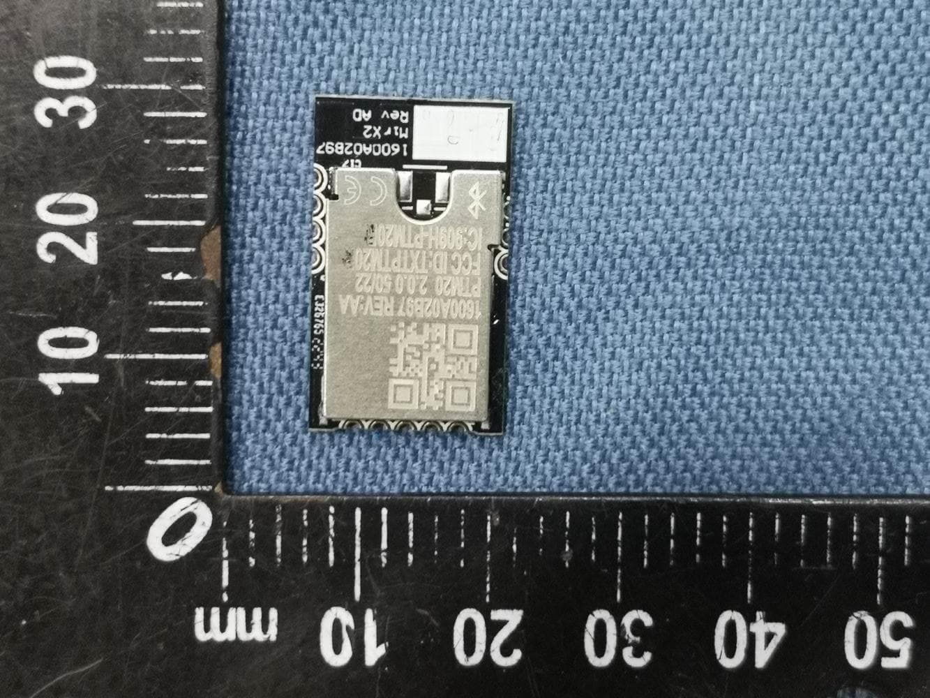
TXTPTM20
Jul 24, 2023MirX2 Bluetooth Module
Equipment Class
DTS - Digital Transmission System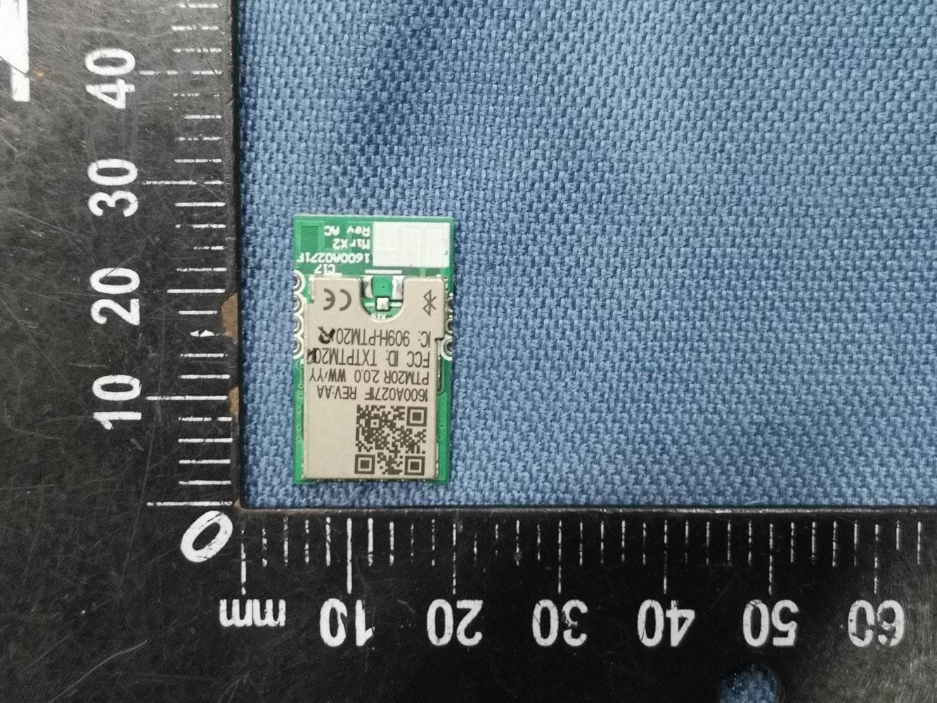
TXTPTM20R
Jul 24, 2023MirX2 Bluetooth Module
Equipment Class
DTS - Digital Transmission System
TXTGCY300-42
Aug 11, 2021Connectivity Module
Equipment Class
DTS - Digital Transmission System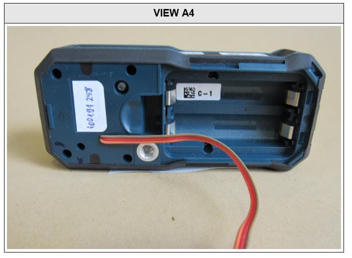
TXTGLM1652XX
Oct 13, 2020Laser Rangefinder
Equipment Class
DTS - Digital Transmission System
TXTGCY30-5T
Sep 21, 2020Bluehound beacon
Equipment Class
DTS - Digital Transmission System