TY7210-0161Access BPL Power-line bridge
Current Technologies, LLC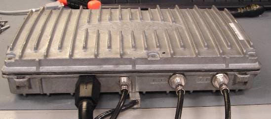
Click to zoom
Application Details
- Equipment Class
- BPL - Access Broadband Over Powerline System
- Date of Grant
- Sep 12, 2007
- Application Purpose
- Original Equipment
- Date of Application
- Jul 02, 2007
- Equipment Note
- Access BPL Power-line bridge
- Frequency Range
- 22.60000000 - 50.00000000
- Company
- Current Technologies, LLC
- Country
- United States
Documents & Files
Document Text
Text extracted from the exhibit documents filed with the FCC. Open a document above to read the original.
Attestation Statements
20420 Century Boulevard Germantown, MD 20874 (301) 944-2700 (phone) (301) 944-2701 (fax) Test Report Attestation According to testing performed by Current Technologies, LLC, the CT Bridge ® URD 5010mvx is in compliance with the electromagnetic compatibility requirements defined in FCC Rules, Part 15, Subpart G. Details are shown in the accompanying test report. Date: July 3, 2007
Cover Letter(s)
20420 Century Boulevard Germantown, MD 20874 (301) 944-2700 (phone) (301) 944-2701 (fax) July 3, 2007 FEDERAL COMMUNICATIONS COMMISSION Office of Engineering & Technology 7435 Oakland Mills Road Columbia, MD 21046 Subject: Request for confidentiality for FCC ID: TY7210-0161 To Whom It May Concern: Pursuant to 47 CFR Sections 0.457 and 0.459, CURRENT Technologies, LLC (“CURRENT”) hereby requests non-disclosure and confidential treatment of the following materials submitted in support of FCC certification application for FCC ID # TY7210-0161. a. Block Diagram b. Internal Photos c. Operational Description d. Installation Instructions The above materials contain trade secrets and proprietary, technical information that CURRENT would customarily guard from competitors. See 47 C.F.R. § 0.457(d)(2). Disclosure or publication of any portion of this confidential material to other parties could cause substantial competitive harm and provide unjustified benefits for competitors. The information in these exhibits is not available to the general public. This information, including that in the internal photos, is not disclosed to third parties except under protection of a confidentiality agreement that prohibits further disclosure. Therefore recipients of this information are constrained by contract from showing the equipment or discussing its operation to anyone not approved by CURRENT. Although the underlying equipment is installed outdoors, all installations (as well as equipment removal and in-situ maintenance) are performed only by certified utility company linemen or contractors, and once installed the equipment resides in the “power space” of utility poles where electric distribution lines are hung. Access to this space is very dangerous and under the National Electric Safety Code is strictly limited to qualified utility workers certified to work within such “power space.” Finally, the underlying equipment is serviceable only by CURRENT or a CURRENT- authorized third party. As a result, the design details of the equipment, including internal photos, are hidden from competitors and protected against public disclosure. The equipment design, as shown in the internal photos, was developed by CURRENT at great expense. Disclosure of this information via the FCC website would convey an unfair and unearned competitive advantage to other companies in this market. CURRENT is entitled to have the information protected pursuant to Worthington Compressors v. Costle, 662 F.2d 45, 51 (D.C. Cir. 1981). Sincerely, Jay Birnbaum Vice President & General Counsel (301) 944-2702 (phone) (301) 944-2701 (fax) [email protected]
Cover Letter(s)
20420 Century Boulevard Germantown, MD 20874 (301) 944-2700 (phone) (301) 944-2701 (fax) July 3, 2007 FEDERAL COMMUNICATIONS COMMISSION Office of Engineering & Technology 7435 Oakland Mills Road Columbia, MD 21046 Subject: FCC ID: TY7210-0161 OET Equipment Authorization Branch: Attached are the necessary documents supporting our request for certification of the CT Bridge URD 5010mvx product family, often referred to as the CT Bridge URD-A. This hardware works in conjunction with the CT OTP URD-A to create a unique system approach to providing BPL services into long underground utility runs serving a large number of transformers. The documents supporting the certification of the CT OTP URD-A will follow shortly under separate cover. This system submitted here is the fully-commercialized version of an earlier submission, under FCC ID TY7210- 0061-0001, which has subsequently been dismissed by the FCC. This new system supports the separate sets of operating bands on the underground medium-voltage wiring as first discussed in the response to FCC correspondence 31027 of June 5, 2006. In a meeting at the FCC lab on August 3, 2006, Dr. Doshi and his colleagues agreed that the three versions would qualify for certification, but only if all three were submitted together. This set of applications fulfills that condition. Particularly as regards the requirements of 15.611 (c)(1), this complete system demonstrates the flexibility necessary to remotely mitigate any potential interference issues as was originally outlined in Jim Mollenkopf’s response to correspondence 31027. We look forward to your favorable response to our application and stand ready to address any questions you might have. Sincerely, Dr. David S. Yaney CTO CURRENT Group, LLC. (301) 944-2900 (phone) (301) 944-2701 (fax) [email protected]
Cover Letter(s)
TO: Andrew Leimer FCC Equipment Authorization Branch FROM: Dr. David S. Yaney CURRENT Group, LLC September 5, 2007 Andrew: I trust the following will address your recent questions regarding our certification submission, FCC ID TY7210-0161, EA717405 (correspondence reference number 33684). Please let me know if any items remain outstanding for you. 1. Since the specific number (0.6 dB) appears in your question we assume that you are referencing the first paragraph under “Conclusion” in section 9.2 of our submitted Report of Measurements, i.e. your concerns are directed at the LV signals. The internal OFDM engine and associated circuitry generating these signals in this equipment is virtually identical to that used in our URD-R bridge, FCC ID TY7210-1050 that was certified in September 2006. The minor differences of circuitry in the current submission are related only to the use of sharper internal bandpass filters necessary for considerations of system integration and would not be expected to have any deleterious impact on emissions. In all cases the test conditions used to measure the values reported are such that the OFDM engine generating the LV signals is forced to transmit at the absolute maximum duty cycle transporting unidirectional (UDP) data traffic. This is an extreme test and is rarely, if ever, the case in normal operation. The transmit power is also set at the absolute maximum using an internal carrier-by-carrier capability to flatten the spectrum on-the-wire to the greatest extent possible. Doing this therefore results in a somewhat harsher test than is absolutely required. We also take considerable care to follow the guidelines of Appendix C, Section 2(c) of the FCC BPL Report and Order precisely. The values reported therefore are absolute maxima identified over frequency and radial position at three unique test sites and the vast majority of that data is under the limits by 2dB or more. In our opinion, strictly demonstrating compliance under the rigorous burden of these test conditions/methodologies provides more-than-adequate assurance of subsequent compliance of our equipment in normal operation when installed in the field. 2. This device is not specifically part of the (newer) SmartGrid system which we discussed during our recent visit to OET on August 23, 2007. While all systems CURRENT offers for sale are capable of transporting SmartGrid (utility) data, the system under consideration here provides considerably better performance than is necessary for that purpose alone and would generally be installed only when true broadband transport capability is necessary. We often make the distinction by referring to BPL systems deployed for the sole purpose of transporting electric utility data as “SmartGrid Only” or “SGO” systems. Our discussions last month revolved around such an SGO system intended for ubiquitous deployment on both underground and overhead utility MV lines.
External Photos
CURRENT Technologies, LLC CT Bridge ® URD 5010mvx External Photos July 3, 2007 1 Photograph EP-1: External Photo of CT Bridge® URD 5010mvx – View of Front Side and connectors CURRENT Technologies, LLC CT Bridge ® URD 5010mvx External Photos July 3, 2007 2 Photograph EP-2: External Photo of CT Bridge® URD 5000mv1 – View of Back Side CURRENT Technologies, LLC CT Bridge ® URD 5010mvx External Photos July 3, 2007 3 Photograph EP-4: External Photo of CT Bridge® URD 5000mv1 – View of Product Label CURRENT Technologies, LLC CT Bridge ® URD 5010mvx External Photos July 3, 2007 4 Photograph EP-5: External Photo of CT Bridge® URD 5000mv1 – View of FCC Label Area
ID Label/Location Info
Document: 300-0000-00xx ™ Revision: A Date: 11/2/06 Page: 1 of 5 Product Labeling Instruction for URD Network Elements APPROVALS TITLE SIGNATURE DATE ORIGINATOR Matt Malagari 11/2/06 MANAGEMENT Neil Donnelly 11/2/06 OPERATIONS Matt Malagari 11/2/06 CM Jim Oestereich 11/2/06 Document: 300-0000-00xx ™ Revision: A Date: 11/2/06 Page: 2 of 5 REFERENCED DOCUMENTATION: 003-0010-0001 Product Barcode Specification 210-0161-000x CT Bridge® URD 210-0063-000x CT OTP (TM) URD 210-0062-000x CT LVR(TM) URD 1.0 General 1.1 Location Each label shall be applied to the unit at the location indicated in Figures 1 and 2, below. Label should be applied so that all vertical and/or horizontal markings can be read in the same direction as other labels on the unit. Figure 1 Location of FCC Label Document: 300-0000-00xx ™ Revision: A Date: 11/2/06 Page: 3 of 5 Figure 2 Location of Product Label 1.2 Markings All human readable markings must be clear and legible when viewed with normal vision at a distance of twelve inches from eye contact. 2.0 ENVIRONMENTAL 2.1 VERIFICATION TEST Verification testing shall consist of rubbing the printed area for a period not to exceed fifteen seconds, with pressure applied with finger, thumb, or common pencil eraser. A minimum thirty seconds cure time, after printing, is required before testing. After testing, the printed area (bars and adjacent spaces) shall be visually examined for clarity and/or distortion. 2.2 LABEL PRINTER The document provides the label specification for the printer with 8 dots/mm, 300 dpi (minimum) print-head resolution. Document: 300-0000-00xx ™ Revision: A Date: 11/2/06 Page: 4 of 5 2.3 BARCODE DARKNESS The darkness (burn temperature) setting should be optimized using barcode verification equipment. 3.0 CONTENTS OF THE LABEL The Product Barcode Label shall contain the following information. • SERIAL NUMBER – The serial number (S/N) printed on the Product Label has a length of 16 characters and is to be printed in both barcode and human readable form. Refer to document 003-0010-0001 for the serial number scheme. • PRODUCT PART NUMBER (ID) – Part Number of the Bill of Material (BOM). • REVISION LEVEL – The revision level of the BOM. • PRODUCT DESCRIPTION (Name) – The description should be the description on the BOM. • MAC ADDRESS - Where applicable the MAC addresses for North Bound, South Bound and Cable Modem shall be printed on the label. • COUNTRY OF ORIGIN – The country of origin is printed in human readable form only (the country of origin is the location where the final assembly of the IRD is completed). • FCC INFORMATION – Depending on the size of the product label the FCC information can be located on the Product Label or will be a separate label placed on the product. 4.0 LABEL LAYOUT 4.1 FCC LABEL THIS DEVICE COMPLIES WITH PART 15 OF THE FCC RULES. OPERATION IS SUBJECT TO THE FOLLOWING CONDITIONS: (1) THIS DEVICE MAY NOT CAUSE HARMFUL INTERFERENCE (2) THIS DEVICE MUST ACCEPT ANY INTERFERENCE RECEIVED INCLUDING INTERFERENCE THAT MAY CAUSE UNDESIRED OPERATION. FCC ID: TY7210-0161 3.5 “ 1.0 “ Figure 3 Sample FCC Label Document: 300-0000-00xx ™ Revision: A Date: 11/2/06 Page: 5 of 5 4.2 PRODUCT LABEL 3.5 “ 1.0 “ Figure 4 Sample Product Label Depending on what product you are building the information for the Product ID, description serial number, revision level, MAC Addresses will change.. 5.0 LABEL PLACEMENT For placement location of the labels refer to the assembly drawing of that specific product. REVISION HISTORY ECO Revision Effective Date Description of change and pages affected A 11/22/06 Initial Release
Test Report
CURRENT Technologies, LLC CT Bridge ® URD 5010mvx Report of Measurements July 3, 2007 1 CURRENT Technologies, LLC Report of Measurements CT Bridge ® URD 5010mvx Table of Contents 1. General Information........................................................................................................................ 2 2. Applicable Documents...................................................................................................................... 3 3. Detailed Applicable EMC Requirements and Limits........................................................................ 4 3.1. Conducted Limits...................................................................................................................... 4 3.2. Radiated Limits......................................................................................................................... 4 4. Procedures for Measuring RF Emissions......................................................................................... 5 4.1. AC Power Line Conducted Emissions Measurements.............................................................. 5 4.2. Radiated Emissions Measurements......................................................................................... 5 4.2.1. Radiated Emissions Measurement – 1.705 MHz to 30 MHz................................................ 5 4.2.2. Radiated Emissions Measurement – 30 MHz to 50 MHz..................................................... 6 4.2.3. Radiated Emissions Measurement – 50 MHz to 1000 MHz................................................. 7 4.2.3.1. Radiated Emissions Measurement – 50 MHz to 1000 MHz – Stage One............................ 7 4.2.3.2. Radiated Emissions Measurement – 50 MHz to 1000 MHz – Stage Two............................ 8 5. System Test Configuration............................................................................................................... 9 5.1. Description of Test Signal and Power Levels.......................................................................... 9 6. Equipment Modifications............................................................................................................... 10 7. Description of the Test Sites.......................................................................................................... 11 8. List of Test Equipment Used.......................................................................................................... 18 9. EMI Test Results............................................................................................................................ 19 9.1. Conducted Emission Data...................................................................................................... 19 9.2. Radiated Emission Data......................................................................................................... 19 CURRENT Technologies, LLC CT Bridge ® URD 5010mvx Report of Measurements July 3, 2007 2 1. General Information Applicant: CURRENT Technologies, LLC Applicant Address: 20420 Century Boulevard Germantown, MD 20874 301-944-2700 Equipment: CT Bridge ® URD 5010mv1 CT Bridge ® URD 5010mv2 CT Bridge ® URD 5010mv3 Equipment Description: The CT Bridge ® URD 5010mvx is part of an Access BPL system. It operates on underground public utility power lines over low-voltage and medium-voltage wires. The CT Bridge ® is the device that routes and controls data traffic between the low- and medium-voltage lines. The CT Bridge ® serves as a gateway to all customers powered from the same distribution transformer as itself. It communicates over the medium-voltage lines via the CT Coupler ® and over the low-voltage system by a standard 240V two-wire connection. Test Operator: Steve Seymour Dates of Testing: May 31, 2007 to June 20, 2007 Test Locations: CURRENT Technologies Orchard Hills Test Area – XFMR A2, XFMR B1, XFMR C1 (North Potomac, Maryland) CURRENT Technologies Field Research and Test Area – XFMR X1, XFMR X3, and XFMR X5 (Urbana, Maryland) Washington Laboratories Open Area Test Site (Gaithersburg, Maryland) Modes of Operation: LV Active (transmitting high-density OFDM signal on LV wire, 4.4 MHz to 20.8 MHz), Upstream MV1 (transmitting high-density QAM signal on MV wire, 22.6 MHz to 24.2 MHz), Upstream MV2 (transmitting high-density QAM signal on MV wire, 24.5 MHz to 26.1 MHz), Upstream MV3 (transmitting high-density QAM signal on MV wire, 26.4 MHz to 28.0 MHz), Downstream MV1 (transmitting high-density QAM signal on MV wire, 29.7 MHz to 35.7 MHz), Downstream MV2 (transmitting high-density QAM signal on MV wire, 36.85 MHz to 42.85 MHz), Downstream MV3 (transmitting high-density QAM signal on MV wire, 44.0 MHz to 50.0 MHz), Lab Normal (powered up and transmitting continuous pings over LV wire) Field Normal (powered up and transmitting continuous downstream traffic) Applicable EMC Specification: FCC Part 15, Subpart G Class of Service: Class A CURRENT Technologies, LLC CT Bridge ® URD 5010mvx Report of Measurements July 3, 2007 3 2. Applicable Documents Testing of emissions was performed in accordance with FCC requirements. 2.1. Federal Communication Commission (FCC), code of Federal Regulations 47, FCC docket 89-103, Part 15: Radio Frequency Devices, Subpart G, October 2005. 2.2. Federal Communication Commission (FCC), code of Federal Regulations 47, FCC docket 89-103, Part 15: Radio Frequency Devices, Section 15.109(b) and 15.209, October 2001. 2.3. FCC/OET, “FCC Procedure for Measuring Electromagnetic Emissions for Digital Devices”, TP-5, March 1989. 2.4. Federal Communication Commission (FCC), Report and Order, FCC-04-245, Appendix C, Measurement Guidelines for Broadband Over Power Line (BPL) Devices or Carrier Current Systems (CCS) and Certification Requirements for Access BPL Devices, October 2004. 2.5. International Special committee on Radio Interference (CISPR) Publication 16, First Edition 1977, “CISPR Specification for Radio In…
Text truncated - open the document above for the full version.
Test Report
CURRENT Technologies, LLC CT Bridge ® URD 5010mvx Report of Measurements – Appendix A July 3, 2007 A-1 Appendix A – Radiated and Conducted Emissions Measurement Data A.1 Conducted Emissions Data Conducted emissions limits do not apply to this Access BPL equipment CURRENT Technologies, LLC CT Bridge ® URD 5010mvx Report of Measurements – Appendix A July 3, 2007 A-2 A.2 Radiated Emissions Data A.2.1 1.705 MHz to 30 MHz Date: June 8, 2007 EUT: CT Bridge URD 5010mv2 (S/N: 1102787900369834) Location: CURRENT Technologies Orchard Hills Test Area – XFMR A2 Mode: LV Signaling (transmitting LV-signal, 4.4 MHz to 20.8 MHz, using nuttcp command) Frequency (MHz) Antenna Location Antenna Height (m) QP Level Measured on Analyzer (dBμV/m) Measurement Distance (m) Distance Correction Factor to 30m (dB) QP Level Corrected to 30m (dBμV/m) 30m Limit (dBμV/m) Margin (dB) 4.49 R45 1.0m 48.0 10.0m -19.1 28.9 29.5 -0.6 5.08 R45 1.0m 46.8 10.0m -19.1 27.7 29.5 -1.8 8.79 C180 1.0m 45.6 10.0m -19.1 26.5 29.5 -3.0 4.88 R45 1.0m 45.5 10.0m -19.1 26.4 29.5 -3.1 4.69 R45 1.0m 45.4 10.0m -19.1 26.3 29.5 -3.2 5.66 R22.5 1.0m 51.3 7.0m -25.3 26.0 29.5 -3.5 Date: June 11, 2007 EUT: CT Bridge URD 5010mv2 (S/N: 1103787900369791) Location: CURRENT Technologies Orchard Hills Test Area – XFMR B1 Mode: LV Signaling (transmitting LV-signal, 4.4 MHz to 20.8 MHz, using nuttcp command) Frequency (MHz) Antenna Location Antenna Height (m) QP Level Measured on Analyzer (dBμV/m) Measurement Distance (m) Distance Correction Factor to 30m (dB) QP Level Corrected to 30m (dBμV/m) 30m Limit (dBμV/m) Margin (dB) 17.38 R67.5 1.0m 48.0 10.0m -19.1 28.9 29.5 -0.6 17.19 R67.5 1.0m 47.8 10.0m -19.1 28.7 29.5 -0.8 16.99 L45 1.0m 46.6 10.0m -19.1 27.5 29.5 -2.0 17.58 R67.5 1.0m 46.2 10.0m -19.1 27.1 29.5 -2.4 17.77 R67.5 1.0m 45.8 10.0m -19.1 26.7 29.5 -2.8 12.50 R157.5 1.0m 45.5 10.0m -19.1 26.4 29.5 -3.1 Date: June 13, 2007 EUT: CT Bridge URD 5010mv2 (S/N: 1103787900369791) Location: CURRENT Technologies Orchard Hills Test Area – XFMR C1 Mode: LV Signaling (transmitting LV-signal, 4.4 MHz to 20.8 MHz, using nuttcp command) Frequency (MHz) Antenna Location Antenna Height (m) QP Level Measured on Analyzer (dBμV/m) Measurement Distance (m) Distance Correction Factor to 30m (dB) QP Level Corrected to 30m (dBμV/m) 30m Limit (dBμV/m) Margin (dB) 10.35 R22.5 1.0m 52.8 7.2m -24.8 28.0 29.5 -1.5 10.55 L67.5 1.0m 50.0 8.3m -22.3 27.7 29.5 -1.9 16.21 R67.5 1.0m 46.4 10.0m -19.1 27.3 29.5 -2.2 10.74 L67.5 1.0m 49.3 8.3m -22.3 27.0 29.5 -2.6 9.96 R67.5 1.0m 45.8 10.0m -19.1 26.7 29.5 -2.8 16.41 R67.5 1.0m 45.0 10.0m -19.1 25.9 29.5 -3.6 CURRENT Technologies, LLC CT Bridge ® URD 5010mvx Report of Measurements – Appendix A July 3, 2007 A-3 Date: May 31, 2007 EUT: CT Bridge URD 5010mv1 (S/N: 1101776900369810) Location: CURRENT Technologies Field Research and Test Area – XFMR X1 Mode: Upstream MV1 (transmitting high-density QAM signal on MV wire, 22.6 MHz to 24.2 MHz) Frequency (MHz) Antenna Location and Polarity Antenna Height (m) Peak Level Measured on Analyzer (dBμV/m) Measurement Distance (m) Distance Correction Factor to 30m (dB) QP Level Corrected to 30m (dBμV/m) 30m Limit (dBμV/m) Margin (dB) 22.78 C0 1.0m 37.88 10.0m -19.08 18.80 29.54 -10.7 23.66 L22.5 1.0m 37.66 10.0m -19.08 18.58 29.54 -11.0 22.81 R67.5 1.0m 37.62 10.0m -19.08 18.54 29.54 -11.0 23.66 C0 1.0m 37.51 10.0m -19.08 18.43 29.54 -11.1 23.85 L22.5 1.0m 37.36 10.0m -19.08 18.28 29.54 -11.3 22.75 R22.5 1.0m 37.21 10.0m -19.08 18.13 29.54 -11.4 Date: June 4, 2007 EUT: CT Bridge URD 5010mv1 (S/N: 1101776900369810) Location: CURRENT Technologies Field Research and Test Area – XFMR X3 Mode: Upstream MV1 (transmitting high-density QAM signal on MV wire, 22.6 MHz to 24.2 MHz) Frequency (MHz) Antenna Location and Polarity Antenna Height (m) Peak Level Measured on Analyzer (dBμV/m) Measurement Distance (m) Distance Correction Factor to 30m (dB) QP Level Corrected to 30m (dBμV/m) 30m Limit (dBμV/m) Margin (dB) 23.08 L22.5 1.0m 44.65 10.0m -19.08 25.57 29.54 -4.0 23.45 L22.5 1.0m 43.98 10.0m -19.08 24.90 29.54 -4.6 23.78 L45 1.0m 37.19 10.0m -19.08 18.11 29.54 -11.4 23.08 R22.5 1.0m 36.55 10.0m -19.08 17.47 29.54 -12.1 23.82 R67.5 1.0m 36.25 10.0m -19.08 17.17 29.54 -12.4 23.48 L90 1.0m 35.89 10.0m -19.08 16.81 29.54 -12.7 Date: June 5, 2007 EUT: CT Bridge URD 5010mv1 (S/N: 1101776900369810) Location: CURRENT Technologies Field Research and Test Area – XFMR X5 Mode: Upstream MV1 (transmitting high-density QAM signal on MV wire, 22.6 MHz to 24.2 MHz) Frequency (MHz) Antenna Location and Polarity Antenna Height (m) Peak Level Measured on Analyzer (dBμV/m) Measurement Distance (m) Distance Correction Factor to 30m (dB) QP Level Corrected to 30m (dBμV/m) 30m Limit (dBμV/m) Margin (dB) 23.58 R22.5 1.0m 40.64 10.0m -19.08 21.56 29.54 -8.0 23.60 C0 1.0m 40.35 10.0m -19.08 21.27 29.54 -8.3 23.79 R22.5 1.0m 39.36 10.0m -19.08 20.28 29.54 -9.3 23.23 C0 1.0m 38.90 10.0m -19.08 19.82 29.54 -9.7 23.15 L22.5 1.0m 35.70 10.0m -19.08 16.62 29.54 -12.9 23.72 L45 1.0m 35.38 10.0m -19.08 16.30 29.54 -13.2 CURRENT Technologies, LLC CT Bridge ® URD 5010mvx Report of Measurements – Appendix A July 3, 2007 A-4 Date: May 31, 2007 EUT: CT Bridge URD 5010mv2 (S/N: 1102787900369833) Location: CURRENT Technologies Field Research and Test Area – XFMR X1 Mode: Upstream MV2 (transmitting high-density QAM signal on MV wire, 24.5 MHz to 26.1 MHz) Frequency (MHz) Antenna Location and Polarity Antenna Height (m) Peak Level Measured on Analyzer (dBμV/m) Measurement Distance (m) Distance Correction Factor to 30m (dB) QP Level Corrected to 30m (dBμV/m) 30m Limit (dBμV/m) Margin (dB) 25.32 L22.5 1.0m 44.44 10.0m -19.08 25.36 29.54 -4.2 25.16 L22.5 1.0m 42.98 10.0m -19.08 23.90 29.54 -5.6 25.31 L90 1.0m 42.37 10.0m -19.08 23.29 29.54 -6.3 25.45 L90 1.0m 42.35 10.0m -19.08 23.27 29.54 -6.3 25.31 L112.5 1.0m 41.23 10.0m -19.08 22.15 29.54 -7.4 25.20 L112.5 1.0m 41.22 10.0m -19.08 22.14 29.54 -7.4 Date: June 4, 2007 EUT: CT Bridge URD 5010mv2 (S/…
Text truncated - open the document above for the full version.
Test Report
CURRENT Technologies, LLC CT Bridge ® URD 5010mvx Interference Mitigation and Avoidance July 3, 2007 1 CURRENT Technologies, LLC Interference Mitigation and Avoidance CT Bridge ® URD 5010mvx 1. General CT Bridge ® URD 5010mvx comes in three different versions, and each version uses a distinct frequency set. The CT OTP ™ URD 5000 can utilize all three frequency sets in order to communicate with CT Bridges on each frequency set. An overview is shown in Figure 1 below. Figure 1: Overall CT Bridge ® URD 5010mvx System Diagram The frequency plan is shown in Figure 2 below. CURRENT Technologies, LLC CT Bridge ® URD 5010mvx Interference Mitigation and Avoidance July 3, 2007 2 Figure 2: CT Bridge ® URD 5010mvx Frequency Plan The CT Bridge ® installs at the distribution transformer, where it bridges between the low voltage and medium voltage lines. The CT Bridge ® is always installed inside a distribution transformer case. The CT OTP device can be installed on a riser pole, where an overhead line goes underground. Note that typically 15 CT Bridges are installed for every CT OTP device. 1.1. Low-Voltage (LV) Signal The LV-signal operates only on the public utility’s low-voltage wiring. It is based on the HomePlug 1.0 standard and operates at frequencies from 4.4 MHz to 20.8 MHz using OFDM signals with carriers spaced approximately 195 kHz apart. The LV signal does not place carriers in the frequency bands specified for amateur radio use. Additional frequency notching of the LV-signal spectrum can be performed as required. Interference mitigation is accomplished by removing specified OFDM carriers from the Bridge’s LV-signal via a software download performed remotely over the power line network. A simple user interface allows the system operator to specify which carriers will be removed. If required, the signal can also be shut down remotely. CURRENT Technologies, LLC CT Bridge ® URD 5010mvx Interference Mitigation and Avoidance July 3, 2007 3 1.2. Upstream Medium-Voltage (MV) Signal The upstream MV-signals operate only on the public utility’s medium-voltage wiring. There are three possible upstream channels, each 1.6 MHz wide, centered on 23.4, 25.3, and 27.2 MHz. The occupied bandwidth for each channel is adjustable to 1600, 800, 400, or 200 kHz. An occupied bandwidth below 1600 kHz can be shifted remotely to anywhere in the original channel. It is thus possible to avoid transmitting on any frequency while maintaining service to BPL customers. Frequencies on all three available channels are pre-chosen to avoid amateur radio frequencies and the excluded frequency bands of FCC Rules, Section 15.615(f)(1). The channel can be changed among the three possibilities by replacing the CT Bridge ® at the transformer. This requires changing every CT Bridge ® on a run, which only takes a few minutes at each site. Each individual CT Bridge ® can be separately addressed and its power separately controlled. Each unit can also be turned off remotely. Power can be reduced remotely across the entire 1600 kHz channel in small increments up to 20 dB. 1.3. Downstream Medium-Voltage (MV) Signal: The downstream MV-signals operate only on the public utility’s medium-voltage wiring. The entire system has 3 possible downstream channels, each 6 MHz wide, centered at 32.7, 39.85, 47.0. MHz. Frequencies on all three available channels are pre-chosen to avoid amateur radio frequencies and the excluded frequency bands of FCC Rules, Section 15.615(f)(1). The channel can be changed among the three possibilities by replacing the CT Bridge ® at the transformer. This requires changing every CT Bridge ® on a run, which only takes a few minutes at each site. Each individual CT Bridge ® can be separately addressed and its power separately controlled. Each unit can also be turned off remotely. Power can be reduced remotely across the entire 6 MHz channel in small increments up to 10 dB. CURRENT Technologies, LLC CT Bridge ® URD 5010mvx Interference Mitigation and Avoidance July 3, 2007 4 2. Output Spectrum Shaping Overview The charts below demonstrate compliance with FCC Rules, Section 15.611(c). 2.1. Default Output Spectrums The following chart shows the default output spectrum of the LV signal, as-shipped from the factory. LV Signal - Default Output Spectrum -140 -130 -120 -110 -100 -90 -80 -70 -60 -50 -40 2.55.07.510.012.515.017.520.022.5 Frequency (MHz) Power (dBm/Hz) The following chart shows the default output spectrum of the Upstream signal (MV2), as-shipped from the factory. Upstream Signal (MV2) - Default Output Spectrum -140 -130 -120 -110 -100 -90 -80 -70 -60 -50 -40 24.324.524.724.925.125.325.525.725.926.126.3 Frequency (MHz) Power (dBm/Hz) CURRENT Technologies, LLC CT Bridge ® URD 5010mvx Interference Mitigation and Avoidance July 3, 2007 5 The following chart shows the default output spectrum of the Downstream signal (MV2), as-shipped from the factory. Downstream Signal (MV2) - Default Output Spectrum -140 -130 -120 -110 -100 -90 -80 -70 -60 -50 -40 35.8536.8537.8538.8539.8540.8541.8542.8543.85 Frequency (MHz) Power (dBm/Hz) 2.2. Notched LV-Signal Output Spectrum The following chart shows the output spectrum of the LV signal following a remote software change which removes carriers 6 through 12. The notch shows the required 20 dB suppression. LV Signal - Notched Tones 6-12 Output Spectrum -140 -130 -120 -110 -100 -90 -80 -70 -60 -50 -40 2.55.07.510.012.515.017.520.022.5 Frequency (MHz) Power (dBm/Hz) CURRENT Technologies, LLC CT Bridge ® URD 5010mvx Interference Mitigation and Avoidance July 3, 2007 6 2.3. Reduced Power MV-Signal Output Spectrum The following chart shows the output spectrum of the Upstream signal (MV2) after a 20 dB reduction in power, made by a software change from a remote location. The measured signal reduction is 21.2 dB. Upstream Signal (MV2) - Output Spectrum Reduced 20 dB -140 -130 -120 -110 -100 -90 -80 -70 -60 -50 -40 24.324.…
Text truncated - open the document above for the full version.
Contact Information
Applicant
David S. Yaney(VP, Advanced Technology Development)
Technical Contact
CURRENT Technologies, LLCSteve Seymour
[email protected]301-944-2903
20420 Century Boulevard · Germantown, Maryland · United States
Non-Technical Contact
CURRENT Technologies, LLCJay Birnbaum
[email protected]301-944-2702
Technical Specifications
| # | Rule Parts | Frequency Range | Power Output |
|---|---|---|---|
| 2 | 15G | 22.6 MHz - 50 MHz | - |
Other Applications from Current Technologies, LLC
TY76030A
May 06, 2009CURRENT Gateway-Bridge OH 6030
Equipment Class
BPL - Access Broadband Over Powerline System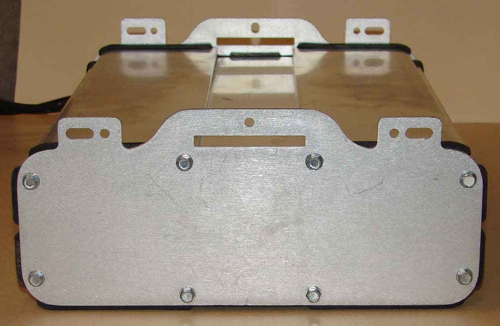
TY76121B
Apr 24, 2008CURRENT Gateway-Bridge URD 6121
Equipment Class
BPL - Access Broadband Over Powerline System
TY76111B
Apr 17, 2008CURRENT Bridge URD 6111
Equipment Class
BPL - Access Broadband Over Powerline System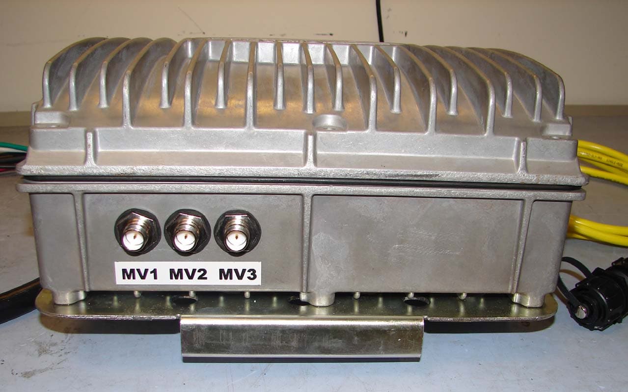
TY7210-0163
Sep 04, 2007URD-A OTP
Equipment Class
BPL - Access Broadband Over Powerline System
TY7210-0152
Jul 25, 2007Access BPL Power Meter
Equipment Class
BPL - Access Broadband Over Powerline System