TY76121BCURRENT Gateway-Bridge URD 6121
Current Technologies, LLC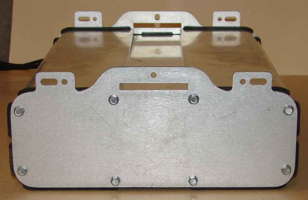
Click to zoom
Application Details
- Equipment Class
- BPL - Access Broadband Over Powerline System
- Date of Grant
- Apr 24, 2008
- Application Purpose
- Original Equipment
- Date of Application
- Mar 06, 2008
- Equipment Note
- CURRENT Gateway-Bridge URD 6121
- Frequency Range
- 4.40000000 - 47.90000000
- Company
- Current Technologies, LLC
- Country
- United States
Documents & Files
Document Text
Text extracted from the exhibit documents filed with the FCC. Open a document above to read the original.
Attestation Statements
20420 Century Boulevard Germantown, MD 20874 (301) 944-2700 (phone) (301) 944-2701 (fax) March 5, 2008 Test Report Attestation I attest that according to testing performed by CURRENT Group, LLC, the CURRENT Gateway- Bridge URD 6121 is in compliance with the electromagnetic compatibility requirements defined in FCC Rules, Part 15, Subpart G. Details are shown in the accompanying test report. Sincerely, Robert Patrick Manager, Product Verification (301) 944-2994 (phone) (301) 944-2701 (fax) [email protected]
Cover Letter(s)
20420 Century Boulevard Germantown, MD 20874 (301) 944-2700 (phone) (301) 944-2701 (fax) March 7, 2008 FEDERAL COMMUNICATIONS COMMISSION Office of Engineering & Technology 7435 Oakland Mills Road Columbia, MD 21046 Subject: Request for confidentiality for FCC ID: TY76121B To Whom It May Concern: Pursuant to 47 CFR Sections 0.457 and 0.459, CURRENT Group, LLC (“CURRENT”) hereby requests non- disclosure and confidential treatment of the following materials submitted in support of FCC certification application for FCC ID # TY76121B. a. Block Diagram – CURRENT Gateway-Bridge URD 6121 b. Internal Photos – CURRENT Gateway-Bridge URD 6121 c. Operational Description – CURRENT Gateway-Bridge URD 6121 d. CURRENT Group URD 6000 Series Install Guide - FCC The above materials contain trade secrets and proprietary, technical information that CURRENT would customarily guard from competitors. See 47 C.F.R. § 0.457(d)(2). Disclosure or publication of any portion of this confidential material to other parties could cause substantial competitive harm and provide unjustified benefits for competitors. The information in these exhibits is not available to the general public. This information, including that in the internal photos, is not disclosed to third parties except under protection of a confidentiality agreement that prohibits further disclosure. Therefore recipients of this information are constrained by contract from showing the equipment or discussing its operation to anyone not approved by CURRENT. Although the underlying equipment is installed outdoors, all installations (as well as equipment removal and in-situ maintenance) are performed only by certified utility company linemen or contractors, and once installed the equipment is protected by tamper indicators to discourage access or modification by consumers or other third parties. Finally, the underlying equipment is serviceable only by CURRENT or a CURRENT-authorized third party. As a result, the design details of the equipment, including internal photos, are hidden from competitors and protected against public disclosure. The equipment design, as shown in the internal photos, was developed by CURRENT at great expense. Disclosure of this information via the FCC website would convey an unfair and unearned competitive advantage to other companies in this market. CURRENT is entitled to have the information protected pursuant to Worthington Compressors v. Costle, 662 F.2d 45, 51 (D.C. Cir. 1981). Sincerely, Jay Birnbaum Vice President & General Counsel (301) 944-2702 (phone) (301) 944-2701 (fax) [email protected]
External Photos
CURRENT Group, LLC CURRENT Bri dge URD 6121 External Photos March 5, 2008 1 Photograph EP-1: External Photo of CURRENT Bridge URD 6121 – View from front side of unit CURRENT Group, LLC CURRENT Bri dge URD 6121 External Photos March 5, 2008 2 Photograph EP-2: External Photo of CURRENT Bridge URD 6121 – View from top of unit CURRENT Group, LLC CURRENT Bri dge URD 6121 External Photos March 5, 2008 3 Photograph EP-3: External Photo of CURRENT Bridge URD 6121 – View from bottom of unit CURRENT Group, LLC CURRENT Bri dge URD 6121 External Photos March 5, 2008 4 Photograph EP-4: External Photo of CURRENT Bridge URD 6121 – View from side of unit CURRENT Group, LLC CURRENT Bri dge URD 6121 External Photos March 5, 2008 5 Photograph EP-5: External Photo of CURRENT Bridge URD 6121 – View from back side of unit
ID Label/Location Info
Document: 300-0000-0075 Revision: A Date: 2/25/2008 Page: 1 of 4 Product Labeling Instruction for URD Network Elements Document: 300-0000-0075 Revision: A Date: 2/25/2008 Page: 2 of 4 1.0 General 1.1 Location Each label shall be applied to the unit at the location indicated in Figures 1 and 2 below. The label should be applied so that all vertical and/or horizontal markings can be read in the same direction as other labels on the unit. Figure 1: Location of FCC Label FCC Label Document: 300-0000-0075 Revision: A Date: 2/25/2008 Page: 3 of 4 Figure 2: Location of Product Label 1.2 Markings All human readable markings must be clear and legible when viewed with normal vision at a distance of twelve inches from eye contact. 2.0 ENVIRONMENTAL 2.1 VERIFICATION TEST Verification testing shall consist of rubbing the printed area for a period not to exceed fifteen seconds, with pressure applied with finger, thumb, or common pencil eraser. A minimum thirty seconds cure time, after printing, is required before testing. After testing, the printed area (bars and adjacent spaces) shall be visually examined for clarity and/or distortion. 2.2 LABEL PRINTER The document provides the label specification for the printer with 8 dots/mm, 300 dpi (minimum) print-head resolution. 2.3 BARCODE DARKNESS The darkness (burn temperature) setting should be optimized using barcode verification equipment. 3.0 CONTENTS OF THE LABEL The Product Barcode Label shall contain the following information. • SERIAL NUMBER – The serial number (S/N) printed on the Product Label has a length of 16 characters and is to be printed in both barcode and human readable form. • PRODUCT PART NUMBER (ID) – Part Number of the Bill of Material (BOM). Product Label Document: 300-0000-0075 Revision: A Date: 2/25/2008 Page: 4 of 4 • REVISION LEVEL – The revision level of the BOM. • PRODUCT DESCRIPTION (Name) – The description should be the description on the BOM. • MAC ADDRESS - Where applicable the MAC addresses for North Bound, South Bound and Cable Modem shall be printed on the label. • COUNTRY OF ORIGIN – The country of origin is printed in human readable form only (the country of origin is the location where the final assembly of the IRD is completed). • FCC INFORMATION – Depending on the size of the product label the FCC information can be located on the Product Label or will be a separate label placed on the product. 4.0 LABEL LAYOUT 4.1 FCC LABEL THIS DEVICE COMPLIES WITH PART 15 OF THE FCC RULES. OPERATION IS SUBJECT TO THE FOLLOWING CONDITIONS: (1) THIS DEVICE MAY NOT CAUSE HARMFUL INTERFERENCE (2) THIS DEVICE MUST ACCEPT ANY INTERFERENCE RECEIVED INCLUDING INTERFERENCE THAT MAY CAUSE UNDESIRED OPERATION. FCC ID: TY76121B 3.5 “ 1.0 “ Figure 3 Sample FCC Label 4.2 PRODUCT LABEL Figure 4: Sample Product Label Depending on what product you are building the information for the Product ID, description serial number, revision level, and MAC Addresses will change.
Test Report
CURRENT Group, LLC CURRENT Gateway-Bridge URD 6121 Report of Measurements March 7, 2008 1 CURRENT Group, LLC Report of Measurements CURRENT Gateway-Bridge URD 6121 Table of Contents 1. General Information ............................................................................................................................... 2 2. Applicable Documents ............................................................................................................................ 3 3. Detailed Applicable EMC Requirements and Limits..................................................................................... 4 3.1 Conducted Limits..................................................................................................................... 4 3.2 Radiated Limits ....................................................................................................................... 4 4. Procedures for Measuring RF Emissions ................................................................................................... 5 4.1 AC Power Line Conducted Emissions Measurements ................................................................... 5 4.2 Radiated Emissions Measurements............................................................................................ 5 4.2.3.1 Radiated Emissions Measurement – 50 MHz to 1000 MHz – Stage One ........................................ 7 4.2.3.2 Radiated Emissions Measurement – 50 MHz to 1000 MHz – Stage Two ........................................ 8 5. System Test Configuration ...................................................................................................................... 9 6. Equipment Modifications......................................................................................................................... 9 7. Description of the Test Sites ................................................................................................................. 10 8. List of Test Equipment Used ................................................................................................................. 17 9. EMI Test Results .................................................................................................................................. 18 9.1 Conducted Emission Data....................................................................................................... 18 9.2 Radiated Emission Data .........................................................................................................18 CURRENT Group, LLC CURRENT Gateway-Bridge URD 6121 Report of Measurements March 7, 2008 2 1. General Information Applicant: CURRENT Group, LLC Applicant Address: 20420 Century Boulevard Germantown, MD 20874 301-944-2700 Equipment: CURRENT Gateway-Bridge URD 6121 Equipment Description: The CURRENT Gateway-Bridge URD 6121 is part of an Access BPL system. It operates on underground public utility power lines over low-voltage and medium-voltage wires. The CURRENT Gateway-Bridge URD 6121 is the device that routes and controls data traffic between the low- and medium-voltage lines. The CURRENT Gateway-Bridge serves as a gateway to all customers powered from the same distribution transformer as itself. It communicates over the medium- voltage lines via the CURRENT Coupler Assembly URD 6300 and over the low- voltage system by a standard 240V two-wire connection. Test Operator: Robert Patrick Dates of Testing: February 12, 2008 to February 29, 2008 Test Locations: 8608 Aqueduct Road – C-7053 (Potomac, Maryland), 12141 McDonald Chapel – A-9204 (Gaithersburg, Maryland) 12157 McDonald Chapel – A-7042 (Gaithersburg, Maryland) Washington Laboratories Open Area Test Site (Gaithersburg, Maryland) Modes of Operation: LV: transmitting a high-density OFDM signal on the low voltage power line in the frequency range (4.4 MHz to 20.8 MHz) by galvanically connecting directly to it. MV: transmitting a high-density OFDM signal on the underground medium voltage cable using the CURRENT Coupler Assembly URD 6300 in the same frequency range as the LV above and also in the 31.4 to 47.9 MHz high band. Applicable EMC Specification: FCC Part 15, Subpart G Class of Service: Class A CURRENT Group, LLC CURRENT Gateway-Bridge URD 6121 Report of Measurements March 7, 2008 3 2. Applicable Documents Testing of emissions was performed in accordance with FCC requirements. 2.1 Federal Communication Commission (FCC), code of Federal Regulations 47, FCC docket 89-103, Part 15: Radio Frequency Devices, Subpart G, October 2005. 2.2 Federal Communication Commission (FCC), code of Federal Regulations 47, FCC docket 89-103, Part 15: Radio Frequency Devices, Section 15.109(b) and 15.209, October 2001. 2.3 FCC/OET, “FCC Procedure for Measuring Electromagnetic Emissions for Digital Devices”, TP-5, March 1989. 2.4 Federal Communication Commission (FCC), Report and Order, FCC-04-245, Appendix C, Measurement Guidelines for Broadband Over Power Line (BPL) Devices or Carrier Current Systems (CCS) and Certification Requirements for Access BPL Devices, October 2004. 2.5 International Special committee on Radio Interference (CISPR) Publication 16, First Edition 1977, “CISPR Specification for Radio Interference Measuring, Apparatus and Measurement Methods”. 2.6 American National Standard, “Interim Standard for Methods of Measurement of Radio-Noise Emissions from Low-Voltage Electrical and Electronic Equipment in the range of 9 kHz to 40 GHz”, ANSI C63.4, 2000. CURRENT Group, LLC CURRENT Gateway-Bridge URD 6121 Report of Measurements March 7, 2008 4 3. Detailed Applicable EMC Requirements and Limits The equipment was evaluated to Federal Communications Commission (FCC) requirements. 3.1 Conducted Limits Conducted emissions limits do not apply to this Access BPL equipment. 3.2 Radiated Limits The following radiated emissions limits apply: Limit of Radiated Emissions Applicable Specification Reference Frequency Range (MHz) Class (μV/m) …
Text truncated - open the document above for the full version.
Test Report
CURRENT Group, LLC CURRENT Gateway-Bridge 6121 Report of Measurements – Appendix A March 7, 2008 A-1 Appendix A – Radiated and Conducted Emissions Measurement Data A.1 Conducted Emissions Data Conducted emissions limits do not apply to this Access BPL equipment A.2 Radiated Emissions Data A.2.1 1.705 MHz to 30 MHz Date: February 7, 2008 EUT: CURRENT Bridge URD 6111 (S/N: 13018AD900433074) Location: CURRENT Potomac Test Area – C-7053 Mode: LV Active (transmitting LV-signal, 4.4 MHz to 20.8 MHz) Frequency Antenna Location Antenna Height (m) QP Level Measured on Analyzer Measurement Distance Distance Correction Factor to 30m QP Level Corrected to 30m (dBμV/m) 30m Limit (dBμV/m) Margin (dB) (MHz) (dBμV/m)(m) (dB) 6.43 0° 1 64.33 3 -40.0 24.33 29.5 -5.17 6.63 0° 1 64.08 3 -40.0 24.08 29.5 -5.42 4.48 0° 1 59.22 3 -40.0 19.22 29.5 -10.28 6.23 0° 1 62.30 3 -40.0 22.30 29.5 -7.20 4.48 22.5° 1 61.52 3 -40.0 21.52 29.5 -7.98 6.63 22.5° 1 65.16 3 -40.0 25.16 29.5 -4.34 11.74 22.5° 1 59.12 3 -40.0 19.12 29.5 -10.38 11.30 22.5° 1 59.24 3 -40.0 19.24 29.5 -10.26 6.42 45° 1 64.16 3 -40.0 24.16 29.5 -5.34 4.48 45° 1 61.73 3 -40.0 21.73 29.5 -7.77 11.51 45° 1 60.59 3 -40.0 20.59 29.5 -8.91 11.90 45° 1 55.69 3 -40.0 15.69 29.5 -13.81 8.97 67.5° 1 63.79 3 -40.0 23.79 29.5 -5.71 4.67 67.5° 1 60.23 3 -40.0 20.23 29.5 -9.27 11.51 67.5° 1 62.81 3 -40.0 22.81 29.5 -6.69 11.90 67.5° 1 53.83 3 -40.0 13.83 29.5 -15.67 6.62 90° 1 65.61 3 -40.0 25.61 29.5 -3.89 6.26 90° 1 64.04 3 -40.0 24.04 29.5 -5.46 4.48 90° 1 60.69 3 -40.0 20.69 29.5 -8.81 9.36 90° 1 59.48 3 -40.0 19.48 29.5 -10.02 6.07 112.5° 1 54.91 3 -40.0 14.91 29.5 -14.59 6.46 112.5° 1 54.98 3 -40.0 14.98 29.5 -14.52 19.15 112.5° 1 51.60 3 -40.0 11.60 29.5 -17.90 19.53 112.5° 1 50.50 3 -40.0 10.50 29.5 -19.00 6.07 135° 1 60.23 3 -40.0 20.23 29.5 -9.27 5.65 135° 1 58.22 3 -40.0 18.22 29.5 -11.28 6.62 135° 1 59.24 3 -40.0 19.24 29.5 -10.26 4.50 135° 1 63.04 3 -40.0 23.04 29.5 -6.46 9.60 157.5° 1 57.68 3 -40.0 17.68 29.5 -11.82 10.53 157.5° 1 55.40 3 -40.0 15.40 29.5 -14.10 10.76 157.5° 1 55.49 3 -40.0 15.49 29.5 -14.01 16.60 157.5° 1 53.73 3 -40.0 13.73 29.5 -15.77 9.80 180° 1 54.35 3 -40.0 14.35 29.5 -15.15 8.98 180° 1 55.22 3 -40.0 15.22 29.5 -14.28 CURRENT Group, LLC CURRENT Gateway-Bridge 6121 Report of Measurements – Appendix A March 7, 2008 A-2 Frequency Antenna Location Antenna Height (m) QP Level Measured on Analyzer Measurement Distance Distance Correction Factor to 30m QP Level Corrected to 30m (dBμV/m) 30m Limit (dBμV/m) Margin (dB) 16.40 180° 1 52.16 3 -40.0 12.16 29.5 -17.34 17.00 180° 1 53.37 3 -40.0 13.37 29.5 -16.13 9.38 202.5° 1 51.67 3 -40.0 11.67 29.5 -17.83 9.80 202.5° 1 52.45 3 -40.0 12.45 29.5 -17.05 16.80 202.5° 1 53.11 3 -40.0 13.11 29.5 -16.39 17.37 202.5° 1 50.58 3 -40.0 10.58 29.5 -18.92 9.81 225° 1 50.84 3 -40.0 10.84 29.5 -18.66 9.61 225° 1 51.66 3 -40.0 11.66 29.5 -17.84 18.96 225° 1 56.78 3 -40.0 16.78 29.5 -12.72 16.60 225° 1 54.63 3 -40.0 14.63 29.5 -14.87 9.38 247.5° 1 47.83 3 -40.0 7.83 29.5 -21.67 9.98 247.5° 1 46.63 3 -40.0 6.63 29.5 -22.87 8.81 247.5° 1 48.17 3 -40.0 8.17 29.5 -21.33 19.10 247.5° 1 55.86 3 -40.0 15.86 29.5 -13.64 9.38 270° 1 47.83 3 -40.0 7.83 29.5 -21.67 9.98 270° 1 46.63 3 -40.0 6.63 29.5 -22.87 8.81 270° 1 48.17 3 -40.0 8.17 29.5 -21.33 19.10 270° 1 55.86 3 -40.0 15.86 29.5 -13.64 9.38 292.5° 1 47.83 3 -40.0 7.83 29.5 -21.67 9.98 292.5° 1 46.63 3 -40.0 6.63 29.5 -22.87 8.81 292.5° 1 48.17 3 -40.0 8.17 29.5 -21.33 19.10 292.5° 1 55.86 3 -40.0 15.86 29.5 -13.64 9.38 315° 1 47.83 3 -40.0 7.83 29.5 -21.67 9.98 315° 1 46.63 3 -40.0 6.63 29.5 -22.87 8.81 315° 1 48.17 3 -40.0 8.17 29.5 -21.33 19.10 315° 1 55.86 3 -40.0 15.86 29.5 -13.64 9.38 337.5° 1 47.83 3 -40.0 7.83 29.5 -21.67 9.98 337.5° 1 46.63 3 -40.0 6.63 29.5 -22.87 8.81 337.5° 1 48.17 3 -40.0 8.17 29.5 -21.33 19.10 337.5° 1 55.86 3 -40.0 15.86 29.5 -13.64 CURRENT Group, LLC CURRENT Gateway-Bridge 6121 Report of Measurements – Appendix A March 7, 2008 A-3 Date: February 21, 2008 EUT: CURRENT Bridge URD 6111 (S/N: 13018AD900433074) Location: CURRENT Gaithersburg Test Area – A-9204 Mode: LV Active (transmitting LV-signal, 4.4 MHz to 20.8 MHz) Frequency Antenna Location Antenna Height (m) QP Level Measured on Analyzer Measurement Distance Distance Correction Factor to 30m QP Level Corrected to 30m (dBμV/m) 30m Limit (dBμV/m) Margin (dB) (MHz) (dBμV/m)(m) (dB) 19.16 0° 1 58.39 3 -40.0 18.39 29.5 -11.11 20.70 0° 1 55.87 3 -40.0 15.87 29.5 -13.63 19.52 0° 1 56.61 3 -40.0 16.61 29.5 -12.89 11.57 0° 1 51.34 3 -40.0 11.34 29.5 -18.16 19.15 22.5° 1 56.67 3 -40.0 16.67 29.5 -12.83 19.30 22.5° 1 55.97 3 -40.0 15.97 29.5 -13.53 18.96 22.5° 1 55.99 3 -40.0 15.99 29.5 -13.51 11.77 22.5° 1 43.83 3 -40.0 3.83 29.5 -25.67 18.96 45° 1 55.37 3 -40.0 15.37 29.5 -14.13 19.15 45° 1 55.69 3 -40.0 15.69 29.5 -13.81 13.80 45° 1 43.77 3 -40.0 3.77 29.5 -25.73 11.77 45° 1 40.03 3 -40.0 0.03 29.5 -29.47 9.63 67.5° 1 47.99 3 -40.0 7.99 29.5 -21.51 8.20 67.5° 1 48.92 3 -40.0 8.92 29.5 -20.58 19.15 67.5° 1 55.31 3 -40.0 15.31 29.5 -14.19 13.63 67.5° 1 47.85 3 -40.0 7.85 29.5 -21.65 8.41 90° 1 44.19 3 -40.0 4.19 29.5 -25.31 9.80 90° 1 49.48 3 -40.0 9.48 29.5 -20.02 19.33 90° 1 54.58 3 -40.0 14.58 29.5 -14.92 19.52 90° 1 53.52 3 -40.0 13.52 29.5 -15.98 4.70 112.5° 1 47.02 3 -40.0 7.02 29.5 -22.48 6.63 112.5° 1 46.67 3 -40.0 6.67 29.5 -22.83 13.68 112.5° 1 46.78 3 -40.0 6.78 29.5 -22.72 19.33 112.5° 1 52.74 3 -40.0 12.74 29.5 -16.76 6.25 135° 1 46.78 3 -40.0 6.78 29.5 -22.72 6.63 135° 1 46.67 3 -40.0 6.67 29.5 -22.83 13.67 135° 1 47.49 3 -40.0 7.49 29.5 -22.01 17.01 135° 1 47.56 3 -40.0 7.56 29.5 -21.94 6.23 157.5° 1 47.01 3 -40.0 7.01 29.5 -22.49 4.90 157.5° 1 45.13 3 -40.0 5.13 29.5 -24.37 13.68 157.5° 1 47.56 3 -40.0 7.56 29.5 -21.94 16.98 157.5° 1 47.60 3 -40.0 7.60 29.5 -21.90 4.70 180° 1 50.30 3 -40.0 10.30 29.5 -19.20 11.77 180° 1 44.54 3 -40.0 4.54 29.5 -24.96 18.96 180° 1 51.90 3 -40.0 11.90 29.5 -17.60 18.56 180° 1 46.95 3 -40.0 6.95 29.5 -22.55 9.36 202.5° 1 51.09 3 -40.0 11…
Text truncated - open the document above for the full version.
Test Setup Photos
CURRENT Group, LLC CURRENT Gateway-Bridge UR D 6121 Report of Measurements – Appendix B March 5, 2008 B-1 Photograph B-1: Test Site Photo – CURRENT Group Potomac Test Area – C-7053 (external) CURRENT Group, LLC CURRENT Gateway-Bridge UR D 6121 Report of Measurements – Appendix B March 5, 2008 B-2 Photograph B-2: Test Site Photo – Grou p Potomac Test Area – C-7053 (open case) CURRENT Group, LLC CURRENT Gateway-Bridge UR D 6121 Report of Measurements – Appendix B March 5, 2008 B-3 Photograph B-3: Test Site Photo – CURRENT Gr oup Gaithersburg Test Area – A-9204 (external) CURRENT Group, LLC CURRENT Gateway-Bridge UR D 6121 Report of Measurements – Appendix B March 5, 2008 B-4 Photograph B-4: Test Site Photo – CURRENT Gr oup Gaithersburg Test Area – A-9204 (open case) NOTE: This equipment was not utilized for the testing. CURRENT Group, LLC CURRENT Gateway-Bridge UR D 6121 Report of Measurements – Appendix B March 5, 2008 B-5 Photograph B-5: Test Site Photo – CURRENT Gr oup Gaithersburg Test Area – A-7042 (external) CURRENT Group, LLC CURRENT Gateway-Bridge UR D 6121 Report of Measurements – Appendix B March 5, 2008 B-6 Photograph B-6: Test Site Photo – CURRENT Gr oup Gaithersburg Test Area – A-7042 (open case)
Contact Information
Applicant
David S. Yaney(VP, Advanced Technology Development)
Technical Contact
Current Technologies, LLCDavid S. Yaney
[email protected]301-944-2700
20420 Century Blvd · Germantown, Maryland · United States
Non-Technical Contact
Current Technologies, LLCJay Birnbaum
[email protected]301-944-2700
Technical Specifications
| # | Rule Parts | Frequency Range | Power Output |
|---|---|---|---|
| 1 | 15G | 4.4 MHz - 47.9 MHz | - |
Other Applications from Current Technologies, LLC
TY76030A
May 06, 2009CURRENT Gateway-Bridge OH 6030
Equipment Class
BPL - Access Broadband Over Powerline System
TY76111B
Apr 17, 2008CURRENT Bridge URD 6111
Equipment Class
BPL - Access Broadband Over Powerline System
TY7210-0161
Sep 12, 2007Access BPL Power-line bridge
Equipment Class
BPL - Access Broadband Over Powerline System
TY7210-0163
Sep 04, 2007URD-A OTP
Equipment Class
BPL - Access Broadband Over Powerline System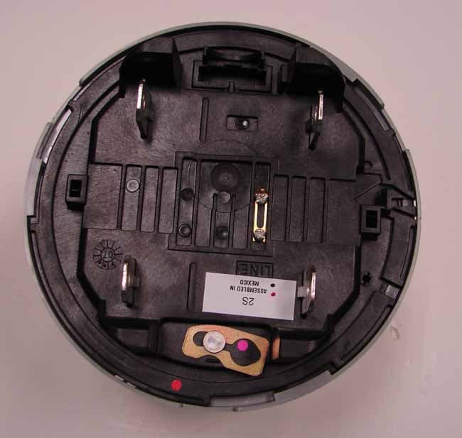
TY7210-0152
Jul 25, 2007Access BPL Power Meter
Equipment Class
BPL - Access Broadband Over Powerline System