TZVTDF1815Radio Control Transmitter
ShenZhen WFLY Technology Development Co., Ltd.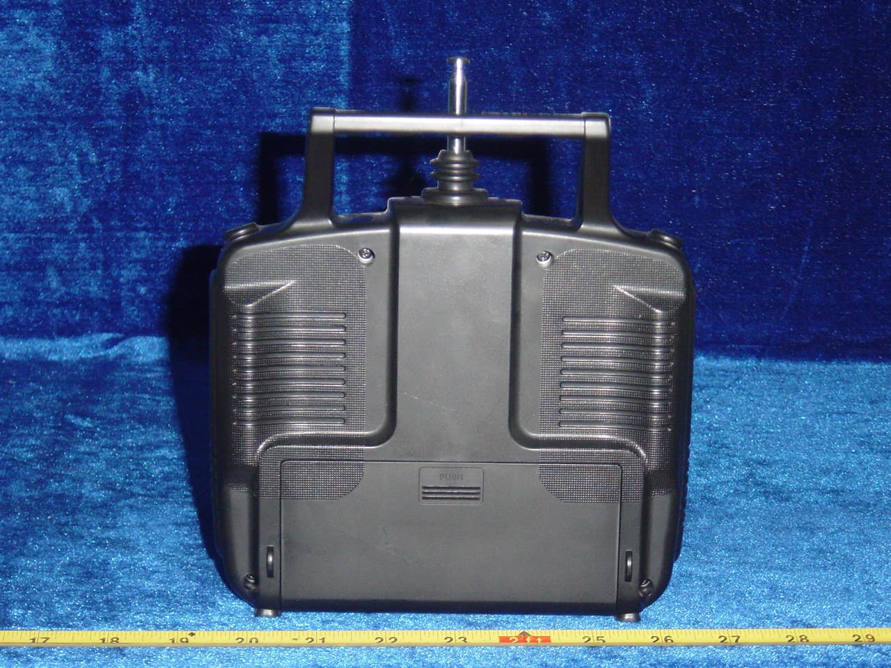
Click to zoom
Application Details
- Equipment Class
- TNB - Licensed Non-Broadcast Station Transmitter
- Date of Grant
- Mar 20, 2006
- Application Purpose
- Original Equipment
- Date of Application
- Mar 20, 2006
- Equipment Note
- Radio Control Transmitter
- Frequency Range
- 72.01000000 - 72.99000000
- Country
- China
Documents & Files
Document Text
Text extracted from the exhibit documents filed with the FCC. Open a document above to read the original.
ID Label/Location Info
FCC ID: TZVTDF1815 This device complies with part 95 of the FCC rules. Proposed Label Location on EUT FCC ID Label Location
Operational Description
Operational Description The FT06 transmitter is composed of signal generator and pulse modulator、signal amplifier. Pulse-modulator signal be output by 13 pin of the CPU EM78P458(IC201), adjusting J201—J206 makes pulse width change in 0.5~2.0 ms, it is achieved to propo control. From Q201 be amplified , pusle signal be adjusted by Q105、Q104 is send to carry frequency OSC circuit, it be FM moduction、time frequency ,The 72MHZ carried frequency be produced is amplified by Q102、Q101、, be send out in sky. Specifications: TransmitterFrequency 72.010-72.990MHz RF Power 20dbm PowerConsumption DC 12V 300mA
Parts List/Tune Up Info
SHEN ZHEN TDF TECHNOLOGY DEVEL0PMENT CO.,LTD. MODEL:FT06 REV:01 BOM ITEMNAME SPECIFICATIONAMOUNTUNINLOCATION 1REGULATORLM78L051PCSIC101 2TRANSISTOR 2SC23141PCSQ101 3TRANSISTOR 2SC4226 1PCSQ102 4TRANSISTOR2SC27141PCSQ103 5TRANSISTOR C9452PCS Q104、Q105 6DIODE HVU300 08051PCSD102 7INDUCTOR 0.33uH ±5% 04101PCSL101 8INDUCTOR 3.9uH ±5% 04101PCSL102 9INDUCTORTDT-T013PCS T103、T104、T105 10INDUCTORTDF-T022PCS T101、T102 11CRYSTAL 72.***MHZ 1PCSY101 12POT 1K + 20% 1PCSVR102 13POT 5K + 20% 1PCSVR101 14 CHIP-RES 1/16W 2.2Ω ±5% 0805 2 PCS R102、R103 15 CHIP-RES 1/16W 10Ω ±5% 0805 1 PCSR105 16CHIP-RES 1/16W 22Ω ±5% 0805 1PCSR110 17CHIP-RES 1/16W 39Ω ±5% 0805 1PCSR107 18CHIP-RES 1/8W 330Ω ±5% 0805 1PCSR106 19CHIP-RES 1/16W 470Ω ±5% 0603 1PCS R104、 20CHIP-RES 1/16W 270Ω ±5% 0603 1PCSR112 21CHIP-RES 1/16W 1K ±5% 0603 1PCSR114 22CHIP-RES 1/10W 1.2K ±5% 0805 1PCSR101 23CHIP-RES 1/16W 1.5K ±5% 06032PCS R109、R115 24CHIP-RES 1/16W 4.7K ±5% 0603 1PCSR108 25CHIP-RES 1/16W 3.3K ±5% 06031PCSR116 26CHIP-RES 1/16W 10K ±5% 0603 4PCS R126、R117、R118、R113 27CHIP-RES 1/16W 47K ±5% 0603 3PCS R119、R120、R121 28CHIP-RES 1/16W 3.9K ±5% 1PCSR123 29CHIP-RES 1/16W 150K ±5% 06031PCSR111 30CHIP-CAP 50V 22P ±5% NPO 08051PCS C101 31CHIP-CAP 50V 27P ±5% NPO 08051PCSC102 32CHIP-CAP 50V 18P ±5% NPO 08051PCSC103 33CHIP-CAP 50V 10P ±5% NPO 08051PCSC104 34CHIP-CAP 50V 330P ±5% NPO 06031PCSC107
Parts List/Tune Up Info
ADJUSTMENTPROCEDURES 1. Transmitter Power Adjustment a).Adjust the DC power supply so that 12V is obtained at the battery terminals. Confirm that the power meter, dummy load and output tester are prepared. b).Turn the power on and plug a XTAL element(72.550MHz)into the crystal socket. c).Adjust T101,T102,T103,T104 and T105 in this order so the power meter reading become maximum. d).Repeat procedure c several times. The RF power meter reading should be more fhan 0.10W when the power is on and at a normal temperature. Then check the current meter reading should be less than 100mA. 2. Transmission Deviation Adjustment a).Set up the unit for the transmission mode. b).Set the Switch 1 to position “1”,then adjust VR101 so that the frequency counter reading is-1.5KHz (72.5485MHz) c).Set the Switch 1 to position “2”,then adjust VR102 so that the frequency counter reading is+1.5KHz(72.5515MHz) d).Repeat procedure b, c, so that maximum deviation is ±1.5 KHz Adjustment setup block diagram ADJUSTMENT SETUP BLOCK DLAGRAM GND 1 SW1 2 V+ NOTE:The elements illustrated above are solely for explaining the adjustment procedure. DC power Supply Power meter Dummy Load Frequency Counter ANT T103 〇T104 〇T105 T101 T102 J101
Test Report
LABORATORIES Report No: FCC 0602019 File reference No: 2006-03-07 Applicant: SHEN ZHEN TDF TECHNOLOGY DEVELOPMENTCO., LT D Product: RADIO CONTROL SYSTEM Model No: Transmitter: FT06 transmitter(72.01072.990MHz) Receiver: FRP06 receiver(72.01072.990MHz) Trademark: TDF Test Standards: FCC 47 CFR PART 95 SUBPART C Test result: It is herewith confirmed and found to comply with the requirements set up by ANSI C63.4&FCC Part 95 Subpart C, regulations for the evaluation of electromagnetic compatibility Approved By Jack Chung Manager Dated: Mar, 07,2006 Results appearing herein relate only to the sample tested The technical reports is issued errors and omissions exempt and is subject to withdrawal at SHENZHEN TIMEWAY TECHNOLOGY CONSULTING CO LTD 5/F,Block 4, Anhua Industrial Zone.,No.8 TaiRan Rd.CheGongMiao,FuTian District, Shenzhen,CHINA. Tel (755) 83448688 Fax (755) 83442996 Report No: 0602019 Page 2 of 25 Date: 2006-03-07 TEST REPORT The report refers only to the sample tested and does not apply to the bulk. This report is issued in confidence to the client and it will be strictly treated as such by the Shenzhen Timeway Technology Consulting Co .,Ltd. It may not be reproduced rather in its entirety or in part and it may not be used for adverting. The client to whom the report is issued may, however, show or send it . or a certified copy there of prepared by the Shenzhen Timeway Technology Consulting co .,Ltd to his customer. Supplier or others persons directly concerned. Shenzhen Timeway Technology Consulting co .,Ltd will not, without the consent of the client enter into any discussion of correspondence with any third party concerning the contents of the report. In the event of the improper use of the report. The Shenzhen Timeway Technology Consulting co .,Ltd reserves the rights to withdraw it and to adopt any other remedies which may be appropriate. Special Statement The testing quality ability of our laboratory meet with "Quality Law of People's Republic of China" Clause 19. The testing quality system of our laboratory meet with ISO/IEC-17025 requirements, which is approved by CNAL. This approval result is accepted by MRA of APLAC. Our test facility is recognized, certified, or accredited by the following organizations: CNAL-LAB Code: L2292 The EMC Laboratory has been assessed and in compliance with CNAL/AC01:2002 accreditation criteria for testing Laboratories (identical to ISO/IEC 17025:1999 General Requirements) for the Competence of testing Laboratories. FCC-Registration No.: 899988 The EMC Laboratory has been registered and fully described in a report filed with the (FCC) Federal Communications commission. The acceptance letter from the FCC is maintained in our files. Registration No.: 899988. IC- Registration No.: IC5205 The EMC Laboratory has been registered and fully described in a report filed with the (IC) Industry Canada. The acceptance letter from the IC is maintained in our files. Registration IC No.: 5205. Report No: 0602019 Page 3 of 25 Date: 2006-03-07 TEST REPORT The report refers only to the sample tested and does not apply to the bulk. This report is issued in confidence to the client and it will be strictly treated as such by the Shenzhen Timeway Technology Consulting Co .,Ltd. It may not be reproduced rather in its entirety or in part and it may not be used for adverting. The client to whom the report is issued may, however, show or send it . or a certified copy there of prepared by the Shenzhen Timeway Technology Consulting co .,Ltd to his customer. Supplier or others persons directly concerned. Shenzhen Timeway Technology Consulting co .,Ltd will not, without the consent of the client enter into any discussion of correspondence with any third party concerning the contents of the report. In the event of the improper use of the report. The Shenzhen Timeway Technology Consulting co .,Ltd reserves the rights to withdraw it and to adopt any other remedies which may be appropriate. Test Report Conclusion Content 1.0 General Details ............................................................................................... 4 1.1 Test Lab Details................................................................................................ 4 1.2 Applicant Details.............................................................................................. 4 1.3 Description of EUT ........................................................................................... 4 1.4 Submitted Sample.............................................................................................. 4 1.5 Test Duration.................................................................................................... 4 1.6 Test Uncertainty................................................................................................ 5 1.7 Test By.......................................................................................................... 5 2.0 List of Measurement Equipment......................................................................... 5 3.0 Technical Details............................................................................................. 7 3.1 Summary of Test Results..................................................................................... 7 3.2 Test Standards.................................................................................................. 7 4.0 EUT Modification............................................................................................. 7 5.0 Test Result.......................................................................................................................... 8 5.1 E.U.T. Operation.............................................................................................. 8 5.2 Test Procedure & Measurement Data...................................................................... 8 5.2.1 Flied Strength of Fundamental.........................................................................…
Text truncated - open the document above for the full version.
Contact Information
Applicant
Cheng Ji(General Manager)
Test Firm
Shenzhen Timeway Testing LaboratoriesJack Chung
Technical Specifications
| # | Rule Parts | Frequency Range | Power Output | Emission | Tolerance |
|---|---|---|---|---|---|
| 1 | 95C | 72.01 MHz - 72.99 MHz | 4.37 mW | 5K50F1D | 0.0020000000 % |
Other Applications from ShenZhen WFLY Technology Development Co., Ltd.
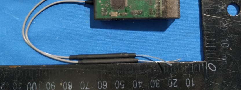
TZVRF209S
Mar 12, 2020Wireless Digital Model Remote Control Receiver
Equipment Class
DSS - Part 15 Spread Spectrum Transmitter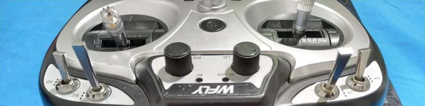
TZVET06
Mar 12, 2020Digital Proportion Model Radio Controller
Equipment Class
DSS - Part 15 Spread Spectrum Transmitter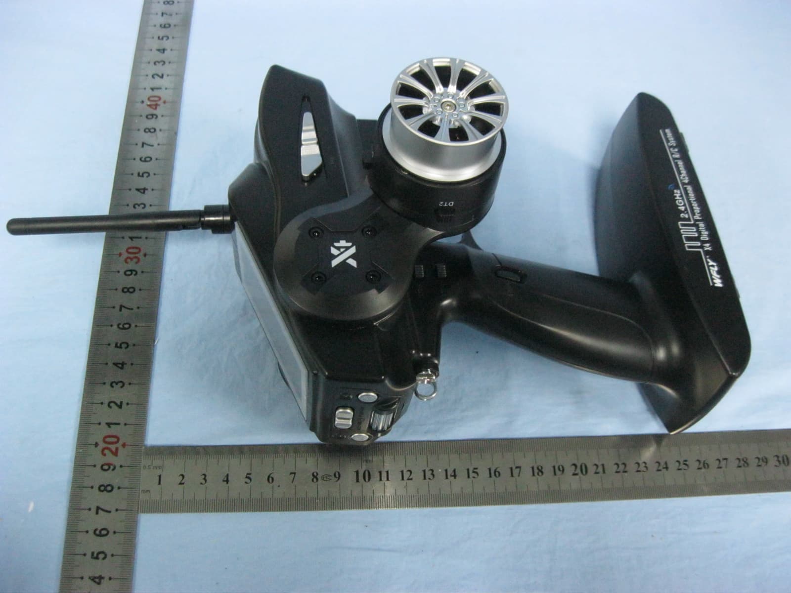
TZVX4
Dec 26, 2013DIGITAL PROPORTIONAL REMOTE CONTROLLER
Equipment Class
DSS - Part 15 Spread Spectrum Transmitter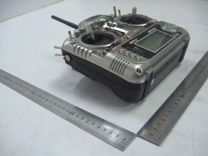
TZVWFT09II
Sep 05, 2011RADIO CONTROL SYSTEM
Equipment Class
DTS - Digital Transmission System
TZVWFT07
Sep 19, 2010RADIO CONTROL SYSTEM
Equipment Class
DXX - Part 15 Low Power Communication Device Transmitter