TZVWFT09IIRADIO CONTROL SYSTEM
ShenZhen WFLY Technology Development Co., Ltd.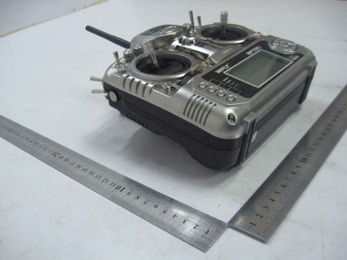
Click to zoom
Application Details
- Equipment Class
- DTS - Digital Transmission System
- Date of Grant
- Sep 05, 2011
- Application Purpose
- Original Equipment
- Date of Application
- Sep 05, 2011
- Equipment Note
- RADIO CONTROL SYSTEM
- Frequency Range
- 2411.00000000 - 2470.00000000
- Country
- China
Documents & Files
Document Text
Text extracted from the exhibit documents filed with the FCC. Open a document above to read the original.
Users Manual
INSTRUCTION MANUAL RADIO CONTROL SYSTEM PCMS 4096 NOTICE Read the instruction before operation! V2 PCMS Receiver, Dual MCU, Dual Antenner.Dual circuits 1 INSTRUCTION Thank you for purchacing product! SERVICE 1.Retailers to provide free maintenance for six months (apart from artificial damage) 2. WFLY retailers will always provide life-long maintance 2 CATALOGUE Contents-------------------------------------------------------------------- Transmitter front----------------------------------------------------------- Transmitter back----------------------------------------------------------- Receiver--------------------------------------------------------------------- Trainer function------------------------------------------------------------ Flying safety warnings---------------------------------------------------- Features--------------------------------------------------------------------- Buttons---------------------------------------------------------------------- 2.4G Code matching------------------------------------------------------ Adjust the stick head----------------------------------------------------- C----------------------------hange the throttle direction of mode1 or 2 1. Model selecting--------------------------------------------------------- 2. Model name------------------------------------------------------------ 3. Model setting----------------------------------------------------------- 4. ATL----------------------------------------------------------------------- 5. Modulation setting----------------------------------------------------- 6. RF setting------------------------------------------------- -------------- 7. Swash select------------------------------------------------------------ 8. Stick setting------------------------------------------------------------- 9. Adjustment--------------------------------------------------------------- 10e.Res t setting-------------------------------------------------------------- 11. Send data-------------------------------------------------------------- 12. Receive data---------------------------------------------------------- 13. Sound------------------------------------------------------------------- 14. Contrast setting------------------------------------------------------- About----------------------------------------------------------------------- Language--------------------------------------------------------------- 1. Monitor------------------------------------------------------------------- 2. Dual rate & Exponential----------------------------------------------- 3. Servo reverse----------------------------------------------------------- 4. End point---------------------------------------------------------------- INSTRUCTION HELICOPTER SYS SETTING NORMAL SETTING 08 09 10 11 12 13 14 15 16 17 18 23 24 25 26 27 27 28 29 30 31 32 33 34 35 35 36 37 38 39 40 3 5. Sub trim---------------------------------------------------------------- 6. Swash param setting------------------------------------------------ 7. Auxiliary channels setting------------------------------------------ 8. Throttle curve setting------------------------------------------------ 9. Pitch curve setting--------------------------------------------------- 10. Revolution mixing--------------------------------------------------- 11. Trim step setting----------------------------------------------------- 12. Throttle cut setting-------------------------------------------------- 13. Fly model switch----------------------------------------------------- 14. Throttle holding setting--------------------------------------------- 15. Fail safe--------------------------------------------------------------- 16. TIMER----------------------------------------------------------------- (1). GYRO sens setting--------------------------------------------- (2). Throttle hovering setting-------------------------------------- (3). Pitch hovering setting------------------------------------------ (4). HI/LO PIT Setting----------------------------------------------- (5). Trim offset setting---------------------------------------------- (6). DELAY------------------------------------------------------------ (7). Governor mixing------------------------------------------------ (8). Swash and THR mixing---------------------------------------- (9). Cuve setting----------------------------------------------------- (10). PROG.NOR.MIX1-7------------------------------------------ (17). PROG.CUR.MIX1-4------------------------------------------ (21). Throttle needle mixing--------------------------------------- (22) .Code matching---------------------------------------------- INSTRUCTION ADVANCED 41 42 43 44 46 48 49 50 51 52 53 54 56 57 58 59 60 61 62 63 64 67 68 69 69 4 INSTRUCTION AIRPLANE SYS SETTING 1.Model selecting---------------------------------------------------------- 2.Model name-------------------------------------------------------------- 3.Model setting------------------------------------------------------------ 4.ATL------------------------------------------------------------------------ 5.AIL-2---------------------------------------------------------------------- 6.Modulation setting------------------------------------------------------ 7.RF setting----------------------------------------------- ----------------- 8.Stick setting------------------------------------------------------------- 9.Adjustment- ------------------------------------------------------------ 10.Reset setting----------------------------------------------------------- 11.Send data-------------------------------------------------------------- 12.Receive data---------------------------------------------------------- 13.Sound------------------------------------------------------------------ 14.Contrast setting-------------------------------------------------------- About----------------------------------------------------------------------- Language------------------------------------------------------------------ NORMA…
Text truncated - open the document above for the full version.
Users Manual
Language This function is to select the language. The selection is as shown in the picture ,if only English or Chinese menu, the function is not exist. INSTRUCTION HELICOPTER 36 NORMAL SETTING(helicopter) 1. MONITOR Monitor shows the servos’ movement situation. In PCMS, this function is to describe the 9 channels output. In PPM, this function is to describe the first 8 channels output. Setting Method: Press menu button, enter system setting, the first function is the monitor. INSTRUCTION HELICOPTER 37 2. DUAL RATE & EXPONENTIAL SETTING (1). AIL (2). ELE (3). RUD Dual rate is to adjust aileron, elevator and rudder travel range. The range is between 0%-120%. Exponential setting is to adjust aileron, elevator and rudder sensitivity when the sticks are around the middle. The range is between -100% to +100%. Setting Method: 1. Select channel Aileron, elevator and rudder are selectable. Press +/- buttons to select channel, OK button to finish setting. 2. Set the switch and its position(0,1,2) Press direction button to select “SWT”, edit it. +/- buttons can select function switch(A-F). After selecting the function switch, press right direction button to enter the switch position setting, use +/- buttons to set. 3. Set dual rate Press direction button to select “D/R”, edit it. Edit one or two parameter. +/- buttons can increase or decrease the value. Press the OK button is to back default. 4. Set exponential Press direction button to select “EX”. Exponential can adjust aileron, throttle and rudder sensitivity as the stick at the middle. 5. Set curve point (normal/advanced) The box under “EX” shows the curve points. Select “Curve setting” in More setting function list. Please refer to Page 27 for detail curve setting. 6. Press EXIT after all the values are finished setting. Servo Switch Dual rate Exponential Curve point Curve picture (please refer to Page 27) INSTRUCTION HELICOPTER 38 3. SERVO REVERSE This function is to change the direction of the servos movement. Setting Method: Use up/down button to select Servo reverse, OK button is to enter editing. Steps: 1. Use direction buttons to select editing part. 2. Use +/- button or OK button to switch the servo movement direction. 3. Press EXIT after setting. Direction (Rev-reverse, Nor-normal) Channel INSTRUCTION HELICOPTER 39 4. END POINT It is to adjust the end of individual servo’s travel. The range is from 0% to 120%. Setting Method: Use up or down button to select End point, OK button is to enter editing. Steps: 1. Use direction buttons to select editing part. 2. Use +/- button or OK button to set the travel value. Press OK for a while backs to default. 3. Press EXIT after setting. Channel Side Value INSTRUCTION HELICOPTER 40 5. SUB TRIM Sub trim makes small changes or corrections to the neutral position of each servo. Range is -120 to +120, default setting is 0. Setting Method: Use up or down button to select Sub trim, OK button is to enter editing. Steps: 1. Use direction buttons to select editing part. 2. Use +/- button or OK button to set the trim value. Press OK for a while backs to default. 3. Press EXIT after setting. We recommend that you center the digital trims before making Sub trim changes, and that you tryto keep all of the Sub trim values as small as possible. Otherwise, when the Sub trims are large values, the servo’s range of travel is restricted on one side. Channel Value High/Low INSTRUCTION HELICOPTER 41 6. SWASH PARAM SETTING This function is to adjust the aileron, elevator and pitch travel range of swash mixing mode. Setting Method: Use up or down button to select Swash param setting, OK button is to enter editing. Steps: 1. Use direction buttons to select editing part. 2. Use +/- button to set the travel. Press OK button for a while is to back default(60%). 3. Press EXIT after setting. Effection direction Value INSTRUCTION HELICOPTER 42 7. AUXILIARY CHANNELS SETTING This function is for channel 5 to channel 9 function setting. Setting Method: Use up or down button to select Swash param setting, OK button is to enter editing. Steps: 1. Use direction buttons to select editing part. 2. Use +/- button to set the switches or knobs. The switches can be set from A to F, the knobs can be set as VA, VB, VC, VL, VR or none(-). 3. Use left or right direction button to set normal or reverse direction of every channel. 4. Press EXIT after setting. Channel Switch Direction INSTRUCTION HELICOPTER 43 8. THROTTLE CURVE SETTING Throttle curve, together with the throttle stick, can be adjusted properly to maximize engine performance at a particular pitch setting. There are two kinds of curve setting, normal (7 points curve), advanced (2-10 points curve), the range is between 0%-120%. The transmitter can set the following curves: NORM, IDLE1, IDLE2, IDLE3. Normal curve is based on hovering, to maximize engine per- formance at a particular pitch setting. Idle curve is for engine proper work in a 3D flight, with a good match between throttle and pitch. Flight mode Dual rate Curve point Curve picture (Please refer to Page 27) Current flight mode INSTRUCTION HELICOPTER 44 Setting Method: Use up/down button to select Throttle curve setting, OK button is to enter editing. Steps: 1. Flight(NORM IDLE1 IDLE2 IDLE3) Use direction buttons to select editing part. Use +/- button to select one curve. 2. Set Dual rate Use direction button to select “D/R” and edit (one or two values can be set separately or together). Press +/- button for seconds can increase or delete the value. Press OK button for seconds is to back default(60%). 3. Curve point setting(Normal/Advanced) The below pane shows the points curve. Select “Curve setting” in “SYS setting”, choose the curve. For detail curve setting method please refer to Page 27. 4. Press EXIT after setting. INSTRUCTION HELICOPTER 45 9. PITCH CURVE SETTING Pitch curve, together with the throttle stick, can be adjusted properly to maximize engine performance at a particular pitch setting. There are two kinds of cu…
Text truncated - open the document above for the full version.
Users Manual
This function is to back default. Setting Method: Press Menu and turn on the transmitter to enter “SYS SETTING” Use up/down button to select “RESET SETTING”, OK button is to enter editing. Steps: 1. Use direction button to select the editing part. 2. Press +/- button to back default. 3. Press EXIT after setting. 10.RESET SETTING INSTRUCTION AIRPLANE 81 11. SEND DATA Two transmitters (WFT09S) can copy data by a trainer cable/data transfer cable. This function together with the next function “Receive data” can realize the data copy. Setting Method: Press Menu and turn on the transmitter to enter “SYS SETTING” Use up/down button to select “SEND DATA”, OK button is to enter editing. Steps: 1. Select the model data you want to send out. 2. Press OK to send. INSTRUCTION AIRPLANE 82 12.RECEIVE DATA Two transmitters (WFT09S) can copy data by a trainer cable/data transfer cable. This function together with the previous function “Send data” can realize the data copy. Setting Method: Press Menu and turn on the transmitter to enter “SYS SETTING” Use up/down button to select “RECEIVE DATA”, OK button is to enter editing. Steps: 1. Press OK to receive data. 2. Restart the transmitter after receiving the data and it works. INSTRUCTION AIRPLANE 83 This function is to select the sound ON and OFF. Setting Method: Press Menu and turn on the transmitter to enter “SYS SETTING” Use up/down button to select “SOUND”, OK button is to enter editing. Steps: 1. Use +/- button to select ON and OFF. 2. Press OK button to confirm. 3. Press EXIT after setting. 13.Sound INSTRUCTION AIRPLANE 84 This function is to adjust the LCD brightness by increasing or decreasing the contrast value. Setting Method: Press Menu and turn on the transmitter to enter “SYS SETTING” Use up/down button to select “RECEIVE DATA”, OK button is to enter editing. Steps: 1. Use +/- button to increase or decrease the value. 2. Press OK button for a while is to back default. 3. Press EXIT after setting. 14.CONTRAST SETTING 16.LANGUAGE This function is to select the language. The selection is as shown in the picture ,if only English or Chinese menu, the function is not exist. INSTRUCTION AIRPLANE 85 NORMAL SETTING(AIRPLANE) 1. MONITOR Monitor shows the servos’ movement situation. In PCMS, this function is to describe the 9 channels output. In PPM, this function is to describe the first 8 channels output. Setting Method: Press menu button, enter system setting, the first function is the monitor. INSTRUCTION AIRPLANE 86 2. DUAL RATE & EXPONENTIAL SETTING (1). AIL (2). ELE (3). RUD Dual rate is to adjust aileron, elevator and rudder travel range. The range is between 0%-120%. Exponential setting is to adjust aileron, elevator and rudder sensitivity when the sticks are around the middle. The range is between -100% to +100%. Setting Method: 1. Select channel Aileron, elevator and rudder are selectable. Press +/- buttons to select channel, OK button to finish setting. 2. Set the switch and its position(0,1,2) Press direction button to select “SWT”, edit it. +/- buttons can select function switch(A-F). After selecting the function switch, press right direction button to enter the switch position setting, use +/- buttons to set. 3. Set dual rate Press direction button to select “D/R”, edit it. Edit one or two parameter. +/- buttons can increase or decrease the value. Press the OK button is to back default. 4. Set exponential Press direction button to select “EX”. Exponential can adjust aileron, throttle and rudder sensitivity as the stick at the middle. 5. Set curve point (normal/advanced) The box under “EX” shows the curve points. Select “Curve setting” in More setting function list. Please refer to Page 27 for detail curve setting. 6. Press EXIT after all the values are finished setting. Servo Switch Dual rate Exponential Curve point Curve picture (please refer to Page 27) INSTRUCTION AIRPLANE 87 3. SERVO REVERSE This function is to change the direction of the servos movement. Setting Method: Use up/down button to select SERVO REVERSE, OK button is to enter editing. Steps: 1. Use direction buttons to select editing part. 2. Use +/- button or OK button to switch the servo movement direction. 3. Press EXIT after setting. Direction (Rev-reverse, Nor-normal) Channel INSTRUCTION AIRPLANE 88 4. END POINT It is to adjust the end of individual servo’s travel. The range is from 0% to 120%. Setting Method: Use up or down button to select END POINT, OK button is to enter editing. Steps: 1. Use direction buttons to select editing part. 2. Use +/- button or OK button to set the travel value. Press OK for a while backs to default. 3. Press EXIT after setting. Channel Side Value INSTRUCTION AIRPLANE 89 5. SUB TRIM Sub trim makes small changes or corrections to the neutral position of each servo. Range is -120 to +120, default setting is 0. Setting Method: Use up or down button to select SUB TRIM, OK button is to enter editing. Steps: 1. Use direction buttons to select editing part. 2. Use +/- button or OK button to set the trim value. Press OK for a while backs to default. 3. Press EXIT after setting. We recommend that you center the digital trims before making Sub trim changes, and that you tryto keep all of the Sub trim values as small as possible. Otherwise, when the Sub trims are large values, the servo’s range of travel is restricted on one side. Channel Value High/Low INSTRUCTION AIRPLANE 90 INSTRUCTION 6. AUXILIARY CHANNELS SETTING This function is for channel 5 to channel 9 function setting. Setting Method: Use up or down button to select AUXILIARY CHANNELS SETTING, OK button is to enter editing. Steps: 1. Use direction buttons to select editing part. 2. Use +/- button to set the switches or knobs. The switches can be set from A to F, the knobs can be set as VA, VB, VC, VL, VR or none(-). 3. Use left or right direction button to set normal or reverse direction of every channel. 4. Press EXIT after setting. Channel Switch Direction AIRPLANE 91 7. THROTTLE CURVE SE…
Text truncated - open the document above for the full version.
Users Manual
This function is to adjust the LCD brightness by increasing or decreasing the contrast value. Setting Method: Press Menu and turn on the transmitter to enter “SYS SETTING” Use up/down button to select “RECEIVE DATA”, OK button is to enter editing. Steps: 1. Use +/- button to increase or decrease the value. 2. Press OK button for a while is to back default. 3. Press EXIT after setting. 14.CONTRAST SETTING 16.LANGUAGE This function is to select the language. The selection is as shown in the picture ,if only English or Chinese menu, the function is not exist. INSTRUCTION GLIDER 131 NORMAL SETTING(AIRPLANE) 1. MONITOR Monitor shows the servos’ movement situation. In PCMS, this function is to describe the 9 channels output. In PPM, this function is to describe the first 8 channels output. Setting Method: Press menu button, enter system setting, the first function is the monitor. INSTRUCTION GLIDER 132 2. DUAL RATE & EXPONENTIAL SETTING (1). AIL (2). ELE (3). RUD Dual rate is to adjust aileron, elevator and rudder travel range. The range is between 0%-120%. Exponential setting is to adjust aileron, elevator and rudder sensitivity when the sticks are around the middle. The range is between -100% to +100%. Setting Method: 1. Select channel Aileron, elevator and rudder are selectable. Press +/- buttons to select channel, OK button to finish setting. 2. Set the switch and its position(0,1,2) Press direction button to select “SWT”, edit it. +/- buttons can select function switch(A-F). After selecting the function switch, press right direction button to enter the switch position setting, use +/- buttons to set. 3. Set dual rate Press direction button to select “D/R”, edit it. Edit one or two parameter. +/- buttons can increase or decrease the value. Press the OK button is to back default. 4. Set exponential Press direction button to select “EX”. Exponential can adjust aileron, throttle and rudder sensitivity as the stick at the middle. 5. Set curve point (normal/advanced) The box under “EX” shows the curve points. Select “Curve setting” in More setting function list. Please refer to Page 27 for detail curve setting. 6. Press EXIT after all the values are finished setting. Servo Switch Dual rate Exponential Curve point Curve picture (please refer to Page 27) INSTRUCTION GLIDER 133 3. ABK. CURVE SETTING This function is used to make the glider speed down. Setting Method: Use up/down button to select ABK. CURVE SETTING, OK button is to enter editing. Steps: 1. Use direction buttons to select editing part. 2. Use +/- button or OK button to switch the servo movement direction. 3. Press EXIT after setting. INSTRUCTION GLIDER 134 4. SERVO REVERSE This function is to change the direction of the servos movement. Setting Method: Use up/down button to select SERVO REVERSE, OK button is to enter editing. Steps: 1. Use direction buttons to select editing part. 2. Use +/- button or OK button to switch the servo movement direction. 3. Press EXIT after setting. Direction (Rev-reverse, Nor-normal) Channel INSTRUCTION GLIDER 135 5. END POINT It is to adjust the end of individual servo’s travel. The range is from 0% to 120%. Setting Method: Use up or down button to select END POINT, OK button is to enter editing. Steps: 1. Use direction buttons to select editing part. 2. Use +/- button or OK button to set the travel value. Press OK for a while backs to default. 3. Press EXIT after setting. Channel Side Value INSTRUCTION GLIDER 136 6. SUB TRIM Sub trim makes small changes or corrections to the neutral position of each servo. Range is -120 to +120, default setting is 0. Setting Method: Use up or down button to select SUB TRIM, OK button is to enter editing. Steps: 1. Use direction buttons to select editing part. 2. Use +/- button or OK button to set the trim value. Press OK for a while backs to default. 3. Press EXIT after setting. We recommend that you center the digital trims before making Sub trim changes, and that you tryto keep all of the Sub trim values as small as possible. Otherwise, when the Sub trims are large values, the servo’s range of travel is restricted on one side. Channel Value High/Low INSTRUCTION GLIDER 137 7. AUXILIARY CHANNELS SETTING This function is for channel 5 to channel 9 function setting. Setting Method: Use up or down button to select AUXILIARY CHANNELS SETTING, OK button is to enter editing. Steps: 1. Use direction buttons to select editing part. 2. Use +/- button to set the switches or knobs. The switches can be set from A to F, the knobs can be set as VA, VB, VC, VL, VR or none(-). 3. Use left or right direction button to set normal or reverse direction of every channel. 4. Press EXIT after setting. Channel Switch Direction INSTRUCTION GLIDER 138 8. TRIM STEP SETTING This function is to change the rate at which the trim moves when the TRIM LEVER is activated. The range is from 1to 250. Generally larger trim steps are for models with larger control throws or for first flights to ensure sufficient trim to properly correct the model. Smaller trim steps are later used to allow very fine adjustments in flight. Setting Method: Use up/down button to select TRIM STEP SETTING, OK button is to enter editing. Steps: 1. Use direction buttons to select editing part. 2. Use +/- button to adjust the size of the step. Repeat as desired for other channels. If you select RESET, the current channel trim value change to 0. 3. Press EXIT after setting. INSTRUCTION GLIDER 139 9. FLAPERON FLAPERON mixing function uses on servo on each of the two ailerons, and uses them for both aileron and flap function. Setting Method: Use up/down button to select FLAPERON, OK button is to enter editing. Steps: 1. Use direction buttons to select editing part. 2. Use +/- button to set value. Press OK button for seconds can back default. 3. Press EXIT after setting. INSTRUCTION GLIDER 140 10. FLAP TRIM FLAP TRIM assigns the primary flaperon control to allow trimming in flight of the flap action of flaperons. Setting Method: Use…
Text truncated - open the document above for the full version.
Block Diagram
Block Diagram MCU output PPM signal Coding, modulation, 2.4G RF output MCU processing 12.00MHZ Crystal oscollators 8.00MHZ Crystal oscollators Peripheral circuit, switch, etc. PA 2.4G Antenna 4.00MHZ Crystal oscollators Ant. 2411~2470MHz
External Photos
SHEN ZHEN WFLY TECHNOLOGY DEVELOPMENT CO., LTD. Model: WFT09II REPORT NO.: STR11088173I FCC PART 15.247 EXHIBIT 2 - EUT EXTERNAL PHOTOGRAPHS EUT View 1 EUT View 2 SHEN ZHEN WFLY TECHNOLOGY DEVELOPMENT CO., LTD. Model: WFT09II REPORT NO.: STR11088173I FCC PART 15.247 EUT View 3 EUT View 4
ID Label/Location Info
SHEN ZHEN WFLY TECHNOLOGY DEVELOPMENT CO., LTD. Model: WFT09II REPORT NO.: STR11088173I FCC PART 15.247 EXHIBIT 1- PRODUCT LABELING Proposed FCC ID Label Format FCC ID: TZVWFT09II This device complies with Part 15 of the FCC Rules. Operation is subject to the following two conditions: (1) This device may not cause harmful interference, and (2) This device must accept any interference received, including interference that may cause undesired operation. Specifications : Text is Black in color and justified. Labels are printed in indelible ink on permanent adhesive silk-screened onto the EUT or shall be affixed at a conspicuous location on the EUT. Proposed Label Location on EUT FCC ID Label Location
ID Label/Location Info
SHEN ZHEN WFLY TECHNOLOGY DEVELOPMENT CO., LTD. Model: WFT09II REPORT NO.: STR11088173I FCC PART 15.247 EXHIBIT 1- PRODUCT LABELING Proposed FCC ID Label Format FCC ID: TZVWFT09II This device complies with Part 15 of the FCC Rules. Operation is subject to the following two conditions: (1) This device may not cause harmful interference, and (2) This device must accept any interference received, including interference that may cause undesired operation. Specifications : Text is Black in color and justified. Labels are printed in indelible ink on permanent adhesive silk-screened onto the EUT or shall be affixed at a conspicuous location on the EUT. Proposed Label Location on EUT FCC ID Label Location
Internal Photos
SHEN ZHEN WFLY TECHNOLOGY DEVELOPMENT CO., LTD. Model: WFT09II REPORT NO.: STR11088173I FCC PART 15.247 EXHIBIT 3 - EUT INTERNAL PHOTOGRAPHS EUT Housing and Board View Solder Board-Component View 1 SHEN ZHEN WFLY TECHNOLOGY DEVELOPMENT CO., LTD. Model: WFT09II REPORT NO.: STR11088173I FCC PART 15.247 Solder Board-Component View 2 Solder Board-Component View 3 SHEN ZHEN WFLY TECHNOLOGY DEVELOPMENT CO., LTD. Model: WFT09II REPORT NO.: STR11088173I FCC PART 15.247 Solder Board-Component View 4 Solder Board-Component View 5 SHEN ZHEN WFLY TECHNOLOGY DEVELOPMENT CO., LTD. Model: WFT09II REPORT NO.: STR11088173I FCC PART 15.247 Solder Board-Component View 6 Solder Board-Component View 7 SHEN ZHEN WFLY TECHNOLOGY DEVELOPMENT CO., LTD. Model: WFT09II REPORT NO.: STR11088173I FCC PART 15.247 Solder Board-Component View 8 Solder Board-Component View 9 SHEN ZHEN WFLY TECHNOLOGY DEVELOPMENT CO., LTD. Model: WFT09II REPORT NO.: STR11088173I FCC PART 15.247 Solder Board-Component View 10
Operational Description
Circuit Description MCU digital base band processor output PPM or PCM signal controlled by all switches and potentiometers. MCU base band processor outputs data on the 2.4G module. With SPI interface, the signal sent to digital base band processor then output RF signal after the demoduiation and decoding. Then 2.4G antenna outputs signal after the signal sent to PA for enlargement. Ratings and System Details data rate:250 kbps asynchronous or packet mode transmission format : 8DR mode Format of RX/TX data Preamble(3 byte ) +SOP(8 byte )+Length(1 byte ) +Payload data (max is 16 bytes ) + CRC (2 byte ) synchronization mechanism for transmitter and receiver devices: 1. At bind mode, the transmitter sends the work channels, ADRRESS CODE,SOP and CRC seed information to the receiver. 2. At work mode, the receiver wait on one of the three work channels, and the transmitter transmit data using the three work channels. 3. If the receiver receives a packet of useful data, it switches to another channel. 4. Repeat the step 2 and step3. Channel spacing =1MHz After binding, three channels are chosen as work channels. Specifications transmitter Transmitter Frequency:2.411-2.470GHz Crystal Tolerance: ±20ppm RF Power: <13 dBm Power Consumption: DC 11.1V 200mA Modulation mode: DSSS A ntenna length: 15 cm
RF Exposure Info
RF Exposure Requirements Product Description: RADIO CONTROL SYSTEM Model No.: WFT09II FCC ID: TZVWFT09II Acorrding to the KDB-447498, the following RF exposure evaluation shall to demonstrate RF exposure compliance. Tx frequency range: 2411~2470MHz Antenna-to-tissue separation: <20 cm Max. Antenna Gain: 2dBi Maximum Output Power: 18.072 mW (at the 2411MHz channel) Maximum Duty Factor: Max. 100% 60/f(GHz) mW = 24.88 mW Source-based time-averaged conducted output power is 18.072 mW =< 60/f Therefore, the transmitter complied with the RF exposure requirements and the SAR is not required.
Schematics
WFT09-SCH-MB-V01.sch-1 - Thu Aug 11 09:45:04 2011 WFTRFS-SCH-RF-V01.sch-1 - Thu Aug 11 10:35:59 2011 WFT09S-SCH-LCM-V01.3.sch-1 - Thu Aug 11 14:50:00 2011 WFT09S-SCH-CON-V01.1.sch-1 - Thu Aug 11 09:14:17 2011 WFT09S-SCH-PWR-V01.sch-1 - Thu Aug 11 09:23:06 2011
Test Report
SHEN ZHEN WFLY TECHNOLOGY DEVELOPMENT CO., LTD. Model: WFT09II REPORT NO.: STR11088173I PAGE 1 OF 33 FCC PART 15.247 FCC Part 15C Measurement and Test Report For SHEN ZHEN WFLY TECHNOLOGY DEVELOPMENT CO., LTD. Flat 618-619, 6/F Chuangye Building No. 1 Qilin Road, Nanshan District, Shenzhen, P.R. China FCC ID: TZVWFT09II Report Concerns: Original Report Equipment Type: RADIO CONTROL SYSTEM Model: WFT09II Report No.: STR11088173I Test Date: 2011-08-17 to 2011-08-31 Issue Date: 2011-09-06 Tested By: Jason Chen / Engineer Reviewed By: Lahm Peng / EMC Manager Approved & Authorized By: Jandy so/PSQ Manager Prepared By: SEM.Test Compliance Service Co., Ltd 3/F, Jinbao Commerce Building, Xin'an Fanshen Road, Bao'an District, Shenzhen, P.R.C.(518101) Tel.: +86-755-33663308 Fax.: +86-755-33663309 Website: www.semtest.com.cn Note: This test report is limited to the above client company and the product model only. …
Text truncated - open the document above for the full version.
Contact Information
Applicant
Cheng Ji(General Manager)
Test Firm
SEM.Test Compliance Service Co., Ltd.Jandy So
Technical Specifications
| # | Rule Parts | Frequency Range | Power Output |
|---|---|---|---|
| 1 | 15C | 2.41 GHz - 2.47 GHz | 11.00 mW |
Other Applications from ShenZhen WFLY Technology Development Co., Ltd.
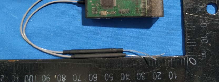
TZVRF209S
Mar 12, 2020Wireless Digital Model Remote Control Receiver
Equipment Class
DSS - Part 15 Spread Spectrum Transmitter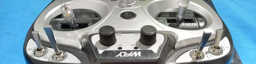
TZVET06
Mar 12, 2020Digital Proportion Model Radio Controller
Equipment Class
DSS - Part 15 Spread Spectrum Transmitter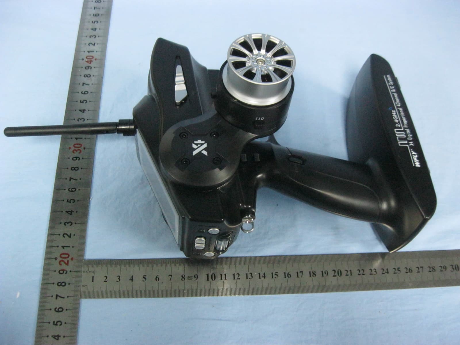
TZVX4
Dec 26, 2013DIGITAL PROPORTIONAL REMOTE CONTROLLER
Equipment Class
DSS - Part 15 Spread Spectrum Transmitter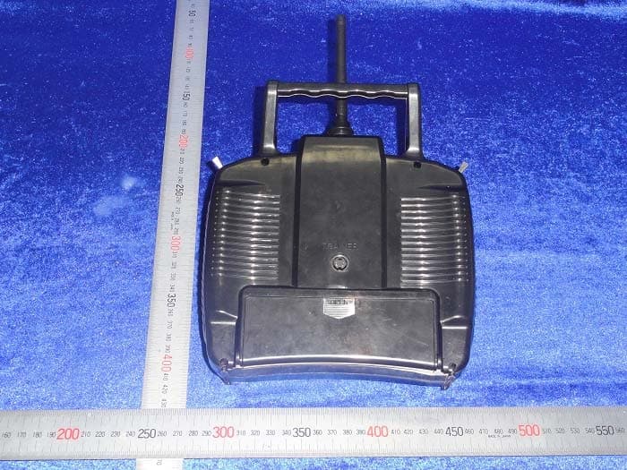
TZVWFT07
Sep 19, 2010RADIO CONTROL SYSTEM
Equipment Class
DXX - Part 15 Low Power Communication Device Transmitter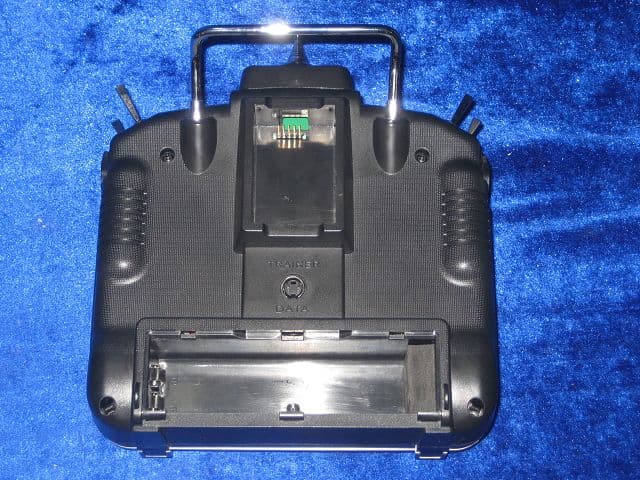
TZVWFT09
May 23, 2007Radio Control Transmitter
Equipment Class
TNB - Licensed Non-Broadcast Station Transmitter