TZVWFT09Radio Control Transmitter
ShenZhen WFLY Technology Development Co., Ltd.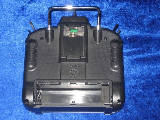
Click to zoom
Application Details
- Equipment Class
- TNB - Licensed Non-Broadcast Station Transmitter
- Date of Grant
- May 23, 2007
- Application Purpose
- Original Equipment
- Date of Application
- May 23, 2007
- Equipment Note
- Radio Control Transmitter
- Frequency Range
- 72.01000000 - 72.99000000
- Country
- China
Documents & Files
Document Text
Text extracted from the exhibit documents filed with the FCC. Open a document above to read the original.
Users Manual
INSTRUCTION MANUAL WFT09 RADIO CONTROL SYSTEM Use in Airplane, Helicopter, Glider, Car, Boat CATALOGUE FLYING SAFETY WARNINGS-------------------------------------------- Transmitter------------------------------------------------------------------- Receiver---------------------------------------------------------------------- Accessories------------------------------------------------------------------ FEATURES------------------------------------------------------------------ BUTTONS-------------------------------------------------------------------- Opening Screen------------------------------------------------------------- Skill---------------------------------------------------------------------------- Trainer function------------------------------------------------------------- SYSTEM SETTING--------------------------------------------------------- 1. Monitor-------------------------------------------------------------------- 2. Dual rate & Exponential setting--------------------------------------- 3. Servo reverse------------------------------------------------------------ 4. End point----------------------------------------------------------------- 5. Sub trim------------------------------------------------------------------- 6. Swash select------------------------------------------------------------ 7. Auxiliary channels setting--------------------------------------------- 8. Throttle curve setting--------------------------------------------------- 9. Pitch curve setting------------------------------------------------------ 10. Revolution mixing----------------------------------------------------- 11. Trim step setting------------------------------------------------------- 12. Throttle cut setting---------------------------------------------------- 13. Fly model switch------------------------------------------------------- 14. Throttle holding setting---------------------------------------------- 15. Fail safe---------------------------------------------------------------- 16. TIMER------------------------------------------------------------------- 17. More setting------------------------------------------------------------ WFT09 INSTRUCTION 1 2 6 9 10 11 11 11 12 13 13 14 14 15 15 15 16 16 17 17 18 18 4 5 7 8 18 18. Language------------------------------------------------------------ SYS SETTING----------------------------------------------------------- Model selecting----------------------------------------------------- Model name--------------------------------------------------------- Model setting-------------------------------------------------------- ATL-------------------------------------------------------------------- Modulation setting-------------------------------------------------- Swash select-------------------------------------------------------- Stick setting--------------------------------------------------------- Rest setting---------------------------------------------------------- Send data------------------------------------------------------------ Receive data-------------------------------------------------------- Contrast setting----------------------------------------------------- ENGINEER MODEL------------------------------------------------ About------------------------------------------------------------------ Language------------------------------------------------------------ TO THE PILOT------------------------------------------------------------ 24 25 25 25 26 26 27 28 28 29 30 31 32 32 32 32 33 WFT09 INSTRUCTION FLYING SAFETY WARNINGS Dangers:If you use it without proper operation, it is possible to hurt you seriously or may even cause death. Warnings:If you use it without proper operation, it may make you or others to hurt badly or may even cause death, and it may cause slight hurt or damage to things. Notices:If you use it without proper operation, it may cause you to hurt slightly or damage things , but it won't hurt you seriously normally. Special Symbol Instruction Forbiddance! Obligation! Warning! Flying Notice(warning) Same frequencies can't fly at the same time. Same frequencies used synchronously will cause the plane to prang or to damage even the modulation ways of AM, FM, PCM are not the same, when the frequencies are identical, it will cause the plane to prang or to damage. Don’t play at night , in rain day ,or in strong wind, which will damage the device or plane. This device is not water-proof. The antenna should be fully pulled out when using it or the signal will be weakened and the control range will reduce, which may cause the crash. Please check every servo works properly and eliminate any disturbing signals before you play it. (If the radio bounces after turning off the power, there may be some disturbances, in this case, please change your channel by exchange crystals ) Checking Notices:Turn on the transmitter first, then the receiver. When turning off the system, turn off the receiver first, then the transmitter. Notices:Children under 14 must be accompanied and instructed by adults! To use the product safely, please pay attention to the instruction as follows. Please pay special attention to the symbol as follows: 1 WFT09 INSTRUCTION CONTENTS AND SPECIFICATIONS TRANSMITTER MODEL NO.: WFT09H MODULATION: FM(PPM) and PCM OUTPUT POWER: ≤700mW POWER SUPPLY: 1.2V x 8 (9.6V) CURRENT DRAIN: 200mA Band: 35, 36, 40, 41, 72MHz TRANSMITTER FRONT 2 WFT09 INSTRUCTION Antenna Power light Alarm light RF light LCD Switch A VA VB VC Trainer switch Menu Exit Increase Decrease Rudder/Elevator stick Elevator trim Rudder trim Power switch Neckstrap attachment Buzzer Up Down Left Right Aileron/Throttle stick Throttle trim Aileron trim Switch B Switch C Switch D Switch E Switch F VR VL OK TRANSMITTER BACK 3 WFT09 INSTRUCTION Handle RF module Battery cover DSC Charge hole RECEIVER MODEL NO.: WFR09 TYPE: 9 CH PCM/PPM, Dual conversion POWER SUPPLY: 1.2V x 4 (4.8V) CURRENT DRAIN: 9.5mA WEIGHT: 19 g DIMENSION: 44.88mm x27.90mm x16.39mm BAND: 35, 36, 40…
Text truncated - open the document above for the full version.
Users Manual
15. TIMER 16. More setting (1). GYRO sens setting This function is to control two electronic clocks used to keep track of time remaining in a competition time allowed, flying time on a tank of fuel, amount of time on a battery, etc. A good gyro will totally eliminate the need for revo.mixing. The gyro wil sense and correct the unwanted motion for you, so you don’t have to spend time to get a complex curve operating properly. It simplifies adjusting/selecting the gyro sensitivity, and can provide more than 2 gyro gain settings. (The higher the gain, the more correction the gyro provides and the “softer” or less responsive the helicopter feels) This function makes the best possible use of the infight adjustable gain of most gyros. 18 Setting Method Use up or down button to select TIMER, OK button is to enter editing. Steps: 1. Use direction buttons to select editing part. 2. Use +/- button for proper adjustment, 3. Press EXIT after setting. WFT09 INSTRUCTION (2). Throttle hovering setting (3). Pitch hovering setting This function is to set the throttle curve trim at the hovering point. Hovering throttle and hovering pitch are fine-tuning adjustments for the throttle and collective pitch curves individually, affecting performance only around the center point and only in the normal condition. They allow in-flight tweaking of the curves for ideal setup. Setting Method Use up or down button to select Throttle hovering setting/ Pitch hover- ing setting, OK button is to enter editing. Steps: 1. Use direction buttons to select editing part. 2. Use +/- button for proper adjustment. 3. Press EXIT after setting. 19 WFT09 INSTRUCTION Setting Method Use up or down button to select GYRO sens setting, OK button is to enter editing. Steps: 1. Use direction buttons to select editing part. 2. Use +/- button for proper adjustment, 3. Press EXIT after setting (5). Trim offset setting This function is to adjust the servo trim at hovering state. Optional separate trims in addition to those for the normal condition. This function is used to automatically change the trim of a helicopter, for example, when transitioned from hover to flying at high speed. A clockwise-rotation rotor helicopter tends to drift to the right at high speed, so an aileron offset may be applied to offset the helicopter to the left. The necessary elevator offset varies with model geometry, so it must be determined by noting collective pitch changes at high speed. The rudder offset is affected by both revo. Mixing and trim lever movement while in the offset function. (4). HI/LO PIT setting This function is to set the high and low pitch position at di- fferent flying modes. 20 Set up separate trims for each of the three idle-up conditions. Adjust the idle-up 2 rudder trim to correct for torque at high speeds. Steps: 1. Open the OFFSET function. 2.Change switch setting to COND. 3. Select IDL2 4. Adjust trim settings as needed.(Ex: rudder to +8%) 5. Close menus and confirm difference in trims between nornal and idle-up 2. WFT09 INSTRUCTION (6). DELAY (7). Governor mixing This function is to delay the aerobatics or throttle cut when the helicopter is in the air so that to avoid the big trim change. The Delay function provides a smooth transition between the trim positions whenever OFFSET, REVO. MIXING, or THROTTLE HOLD functions are turned on and off. This function is to set the governor. The Governor mixing function is used to adjust the GV-1(Governor) speed settings(rS1,rS2,rS3) from the transmitter. Set up a delay on all 3 channels to ease the transition from one flight condition to another so there are “hard jumps”. Steps: 1. Open the DELAY function. 2. Adjust AIL response as needed. (Ex: aileron to +8%) 3. Repeat for other channels. 4. Close menus and confirm slowed transitions. Set up a Gv1 governor to use both channels into the reeiver and switch between the governor settings auto- matically when changing conditions. Consider setting the battery FailSafe settings and other helpful functions on the GV-1 itself. Steps: 1. Open and activate the GOVERNOR function. 2. Optional: change cut-off channel to channel 8 and assign switch and direction for on/off(channel 8). 3. Optional: change switch assignment to select governor settings. Ex: select switch that selects the conditions. 4. Adjust governor speed settings per switch position or condition as needed.(Ex: defaults are fine.) Allows head speed adjustment from transmitter. 5. Close the function. 21 WFT09 INSTRUCTION (8). Swash and THR mixing 22 This function is to adjust throttle and pitch mix function. (9). Curve Setting WFT09 INSTRUCTION There are 2 kinds of setting, Normal and Advanced. (10)-(16). PROG. NOR. MIX1-7 (17)-(20). PROG. CUR. MIX1-4 The mix program is to adjust the flying pose. There are 7series programs with the same set method. There are 4 serious curve mix program, the curve is made up by 2 to 11 point. WFT09 INSTRUCTION 23 (21). Throttle needle mixing 24 Throttle needle is a pre-programmed mix that automatically moves an in-flight mixture servo in response to the Throttle Stick imputs for perfect engine tuning at all throttle settings. This function is particularly popular with contest pilots who fly in a large variety of locations, needing regular engine tuning adjustments, and requiring perfect engine response at all times and in all maneuvers. Also popular to minimize flooding at idle of inverted engine installations or installations with a high tank position. Not need for fuel injection engine, which do this automatically. 17. Language Setting Method Use up or down button to select Throttle needle mixing, OK button is to enter editing. Steps: 1. Use direction buttons to select editing part. 2. Ajust the travels as needed to match your engine by slowly moving the stick to each of the points, then adjusting the percentage at that point until the engine is properly tuned. 3.Set curves for other conditions. 4. Press EXIT after setting. This function is to select the langua…
Text truncated - open the document above for the full version.
ID Label/Location Info
FCC ID: TZVWFT09 This device complies with part 95 of the FCC rules. Proposed Label Location on EUT FCC ID Label Location
Operational Description
Operational Description The WFT09 transmitter is composed of signal generator and pulse modulator、signal amplifier. Pulse-modulator signal be output by 13 pin of the CPU ATMEGA128(IC101), adjusting J201—J206 makes pulse width change in 0.5~2.0 ms, it is achieved to propo control. From Q301、Q302 be amplified , pusle signal be adjusted by Q105、Q104 is send to carry frequency OSC circuit, it be FM moduction、time frequency ,The 72MHZ carried frequency be produced is amplified by Q102、Q101、, be send out in sky. Specifications: TransmitterFrequency 72.010-72.990MHz RF Power 20dbm PowerConsumption DC 12V 300mA
Parts List/Tune Up Info
SHEN ZHEN WFLY TECHNOLOGY DEVEL0PMENT CO.,LTD. MODEL:WFT09 REV:01 BOM ITEMNAME SPECIFICATION AMOUNTUNIN LOCATION 1 CHIP-RES 1/16W 0Ω ±5% 0603 3 PCS R142 R143 R144 2 CHIP-RES 1/16W 5.1Ω ±5% 1206 2 PCS R135 R136 3 CHIP-RES 1/16W 100Ω ±5% 0603 9 PCS R101 R102 R103 R104 R105 R106 R107 R108 R109 4 CHIP-RES 1/16W 220Ω ±5% 0603 1 PCS R129 5 CHIP-RES 1/16W 330Ω ±5% 0603 1 PCS R128 6 CHIP-RES 1/16W 1KΩ ±5% 0603 1 PCS R127 7 CHIP-RES 1/16W 5.1K ±5% 0603 9 PCS R110 R111 R112 R113 R124 R126 R130 R132 R137 8 CHIP-RES 1/16W 4.7KΩ±5% 0603 2 PCS R140 R141 9 CHIP-RES 1/16W 100K ±5% 0603 2 PCS R138 R139 10 CHIP-RES 1/16W 10KΩ ±5% 0603 6 PCS R116 R117 R118 R119 R125 R133 11 CHIP-RES 1/16W 18KΩ ±5% 0603 1 PCS R114 12 CHIP-RES 1/16W 20KΩ ±5% 0603 1 PCS R131 13 CHIP-RES 1/16W 68KΩ ±5% 0603 1 PCS R115 14 CHIP-RES 1/16W 330K ±5% 0603 5 PCS R120 R121 R122 R123 R134 15 CHIP-CAP 50V 30P ±5% 0603 6 PCS C115 C116 C117 C118 C119 C120 16 CHIP-CAP 50V 222 ±10% 0603 13 PCS C101 C102 C103 C104 C105 C106 C108 C109 C110 C111 C112 C113 C114 17 CHIP-CAP 50V 103 ±20% 0603 8 PCS C123 C124 C126 C128 C133 C135 C137 C139 18 CHIP-CAP 50V 104 ±20% 0603 5 PCS C121 C122 C130 C131 C140 19 ZENER BAT85 0805 4 PCS D104 D105 D106 D107 20 TRANSISTOR贴片三极管 2SC945 1 PCS Q101 21 CHIP-CAP 100uF 16V 1 PCS C125 22 CHIP-CAP 10 uF 6.3V 6 PCS C127 C129 C132 C134 C136 C138 23 REGULATOR 78M05 2 PCS IC103A IC103B 24 REGULATOR LM317 1 PCS IC104 25 REGULATOR ATMEGA128 1 PCS IC101 26 REGULATOR CD4051B 1 PCS IC102 27 REGULATOR 24C256 1 PCS IC105 28 ZENER IN4001 2 PCS D101 D103 29 ZENER 15V 1 PCS D102 30 INDUCTOR 10uH 0410 3 PCS L101 L102 L103 31 CRYSTAL 8.00MHZ 1 PCS Y101 32 2.0*2P 2 PCS J101 J102 33 2.0*6P 2 PCS J103 J401 34 2.0*12P 2 PCS J501 J502 35 2.0*13P 1 PCS J402 36 2.0*14P 1 PCS J301 37 2.0*11P 1 PCS J202 38 2.0*13P 1 PCS J201 39 FT09AH--1CPUS03 1 PCS PCB 1 CHIP-RES 1/16W 56KΩ ±5% 0603 1 PCS R204 2 CHIP-RES 1/16W 100KΩ ±5% 0603 5 PCS R205 R206 R207 R208 R209 3 CHIP-RES 1/16W 220KΩ ±5% 0603 1 PCS R202 4 CHIP-RES 1/16W 910KΩ ±5% 0603 1 PCS R203 5 CHIP-CAP 50V 30P ±5% 0603 13 PCS C209 C210 C211 C212 C213 C214 C215 C216 C217 C218 C219 C220 C221 6 CHIP-CAP 50V 104P ±20% 0603 2 PCS C223 C224 7 CHIP-CAP 50V 105P ±20% 0805 8 PCS C201 C202 C203 C204 C205 C206 C207 C208 8 CHIP-CAP 10uF/6.3V 1 PCS C222 9 ZENERLED 1 PCS D201 10 REGULATOR NT7502(LCM) 1 PCS LCMD201 11 CPU IC ATMEGA128 1 PCS IC101 12 2.0*11P 1 PCS J202 13 2.0*13P 1 PCS J201 14 3*6*4.3 9 PCS K201 K202 K203 K204 K205 K206 K207 K208 K209 15 FT09AH--2LCMS03 1 PCS PCB 1 CHIP-RES 1/16W 1KΩ ±5% 0603 6 PCS R301 R303 R306 R307 R309 R310 2 CHIP-RES 1/16W 1.2KΩ ±5% 0603 1 PCS R304 3 CHIP-RES 1/16W 5.1KΩ ±5% 0603 1 PCS R308 4 CHIP-RES 1/16W 10KΩ ±5% 0603 1 PCS R302 5 CHIP-RES 1/16W 47KΩ ±5% 0603 1 PCS R305 6 50V 102 ±10% 0603 6 PCS C301 C303 C304 C305 C309 C310 7 CHIP-CAP 50V 103 ±10% 0603 2 PCS C302 C307 8 INDUCTOR 10uH 0410 5 PCS L301 L302 L303 L304 L305 9 TRANSISTOR 2SC945 2 PCS Q301 Q302 10 AV 1 PCS J202 11 2.54*5 1.5u 16mm 1 PCS J303 12 2.0*2P 2 PCS K301 K302 13 2.0*3P 2 PCS VR501 VR503 14 2.0*14P 1 PCS J301 15 FT09AH--3RFDBS03 1 PCS PCB 1 CHIP-RES 1/16W 5.1KΩ ±5% 0603 6 PCS R402 R403 R405 R407 R408 R409 2 CHIP-RES 1/16W 20KΩ ±5% 0603 3 PCS R401 R404 R406 3 CHIP-CAP 50V 102 ±10% 0603 3 PCS C401 C402 C405 4 CHIP-CAP 50V 103 ±10% 0603 1 PCS C403 5 CHIP-CAP 10uF/6.3V A型 1 PCS C404 6 TRANSISTOR 2SC945 3 PCS Q401 Q402 Q403 7 ZENER Ф5 1 PCS D401 8 ZENER Ф5 1 PCS D402 9 ZENER Ф5 1 PCS D403 10 BZ 1 PCS BZ401 11 1 PCS K401 12 2.0*6P 1 PCS J401 13 2.0*11P 2 PCS J601 J602 14 2.0*13P 1 PCS J402 15 FT09AH--4MKZBS03 1 PCS PCB 1 3*6*4.3 8 PCS K501A K501B K502A K502B K503A K503B K504A K504B 2 FT09AH--5YGWTS03 4 PCS PCB SHEN ZHEN WFLYF TECHNOLOGY DEVEL0PMENT CO.,LTD. MODEL:WFTRF01 REV:01 BOM ITEMNAME SPECIFICATION AMOUNTUNIN LOCATION 1 CHIP-RES 1/16W 2.2Ω ±5% 0805 2 PCS R102 R103 2 CHIP-RES 1/16W 10Ω ±5% 0805 1 PCS R105 3 CHIP-RES 1/16W 22Ω ±5% 0805 1 PCS R110 4 CHIP-RES 1/16W 39Ω ±5% 0805 1 PCS R107 5 CHIP-RES 1/16W 0Ω ±5% 0805 1 PCS R106 6 CHIP-RES 1/16W 470Ω ±5% 0603 1 PCS R104 7 CHIP-RES 1/16W 270Ω ±5% 0603 1 PCS R112 8 CHIP-RES 1/16W 1KΩ ±5% 0603 1 PCS R114 9 CHIP-RES 1/16W 1.2K ±5% 0805 1 PCS R101 10 CHIP-RES 1/16W 1.5K ±5% 0603 2 PCS R109 R115 11 CHIP-RES 1/16W 2K ±5% 0603 1 PCS R108 12 CHIP-RES 1/16W 3.3K ±5% 0603 1 PCS R116 13 CHIP-RES 1/16W 10KΩ ±5% 0603 3 PCS R117 R118 R122 14 DIODE HVU300A 0603 1 PCS R113/D102 15 CHIP-RES 1/16W 47KΩ ±5% 0603 3 PCS R119 R120 R121 16 CHIP-RES 1/16W 220K ±5% 0603 1 PCS R111 17 CHIP-CAP 50V 56P ±5% 0805 1 PCS C101 18 CHIP-CAP 50V 20P ±5% 0805 2 PCS C102 C104 19 CHIP-CAP 50V 18P ±5% 0805 1 PCS C103 20 CHIP-CAP 50V 330P ±5% 0603 1 PCS C107 21 CHIP-CAP 50V 15P ±5% 0805 1 PCS C112 22 CHIP-CAP 50V 22P ±5% 0603 3 PCS C116 C117 C119 23 CHIP-CAP 50V 10P ±5% 0603 1 PCS C131 24 CHIP-CAP 50V 5P ±5% 0603 1 PCS C118 25 CHIP-CAP 50V 62P ±5% 0603 1 PCS C120 26 CHIP-CAP 50V 100P ±5% 0603 1 PCS C121 27 CHIP-CAP 50V 103 ±10% 0805 1 PCS C106 28 CHIP-CAP 50V 102 ±10% 0603 5 PCS C124 C126 C127 C128 C129 29 CHIP-CAP 50V 103 ±10% 0603 6 PCS C108 C111 C113 C114 C122 C123 C132 30 CHIP-CAP 50V 104 ±20% 0603 1 PCS C109 31 TRANSISTOR 2SC4226 1 PCS Q102 32 TRANSISTOR3880 2 PCS Q106 Q1 33 TRANSISTOR2714 1 PCS Q103 34 TRANSISTOR 2SC945 2 PCS Q104 Q105 35 CHIP-CAP 50V 332 ±10% 1 PCS C125 36 TRANSISTOR 2SC2314F 1 PCS Q101 37 INDUCTOR 0.33uH 0410 ±5% 1 PCS L101 38 INDUCTOR 3.9uH 0410 ±5% 1 PCS L102 39 INDUCTOR WFLYT01 3 PCS T103 T104 T105 40 INDUCTOR WFLYT02 2 PCS T101 T102 41 50U 1 PCS Y102 42 1K ±20% 1 PCS VR102 43 5K ±20% 1 PCS VR101 44 2.54×5.1 1 PCS J101 45 100uF/16V 5×11 2 PCS C110 C115 46 6mm 1 PCS JP1 47 78L05 1 PCS IC101 48 WFTRF01 1PCS PCB
Test Report
ISO/IEC17025 Accredited Lab. Report No: FCC 0704156 File reference No: 2007-05-19 Applicant: SHEN ZHEN WFLY TECHNOLOGY DEVELOPMENT CO., LTD. Product: RADIO CONTROL SYSTEM Model No: WFT09tranmitter,WFTRF01-FM(72.010-72.990MHz); WFT09-C receiver(72.010-72.990MHz), WFT09-Preceiver(72.010-72.990MHz) Trademark: WFLY Test Standards: FCC 47 CFR PART 95 SUBPART C Test result: It is herewith confirmed and found to comply with the requirements set up by ANSI C63.4&FCC Part 95 Subpart C, regulations for the evaluation of electromagnetic compatibility Approved By Jack Chung Manager Dated: May 19,2007 Results appearing herein relate only to the sample tested The technical reports is issued errors and omissions exempt and is subject to withdrawal at SHENZHEN TIMEWAY TECHNOLOGY CONSULTING CO LTD 5/F,Block 4, Anhua Industrial Zone.,No.8 TaiRan Rd.CheGongMiao,FuTian District, Shenzhen,CHINA. Tel (755) 83448688 Fax (755) 83442996 Report No: 0704156 Page 2 of 31 Date: 2007-05-19 TEST REPORT The report refers only to the sample tested and does not apply to the bulk. This report is issued in confidence to the client and it will be strictly treated as such by the Shenzhen Timeway Technology Consulting Co .,Ltd. It may not be reproduced rather in its entirety or in part and it may not be used for adverting. The client to whom the report is issued may, however, show or send it . or a certified copy there of prepared by the Shenzhen Timeway Technology Consulting co .,Ltd to his customer. Supplier or others persons directly concerned. Shenzhen Timeway Technology Consulting co .,Ltd will not, without the consent of the client enter into any discussion of correspondence with any third party concerning the contents of the report. In the event of the improper use of the report. The Shenzhen Timeway Technology Consulting co .,Ltd reserves the rights to withdraw it and to adopt any other remedies which may be appropriate. Special Statement: The testing quality ability of our laboratory meet with "Quality Law of People's Republic of China" Clause 19. The testing quality system of our laboratory meet with ISO/IEC-17025 requirements, which is approved by CNAL. This approval result is accepted by MRA of APLAC. Our test facility is recognized, certified, or accredited by the following organizations: CNAL-LAB Code: L2292 The EMC Laboratory has been assessed and in compliance with CNAL/AC01:2002 accreditation criteria for testing Laboratories (identical to ISO/IEC 17025:1999 General Requirements) for the Competence of testing Laboratories. FCC-Registration No.: 899988 The EMC Laboratory has been registered and fully described in a report filed with the (FCC) Federal Communications commission. The acceptance letter from the FCC is maintained in our files. Registration No.: 899988. IC- Registration No.: IC5205 The EMC Laboratory has been registered and fully described in a report filed with the (IC) Industry Canada. The acceptance letter from the IC is maintained in our files. Registration IC No.: 5205. Report No: 0704156 Page 3 of 31 Date: 2007-05-19 TEST REPORT The report refers only to the sample tested and does not apply to the bulk. This report is issued in confidence to the client and it will be strictly treated as such by the Shenzhen Timeway Technology Consulting Co .,Ltd. It may not be reproduced rather in its entirety or in part and it may not be used for adverting. The client to whom the report is issued may, however, show or send it . or a certified copy there of prepared by the Shenzhen Timeway Technology Consulting co .,Ltd to his customer. Supplier or others persons directly concerned. Shenzhen Timeway Technology Consulting co .,Ltd will not, without the consent of the client enter into any discussion of correspondence with any third party concerning the contents of the report. In the event of the improper use of the report. The Shenzhen Timeway Technology Consulting co .,Ltd reserves the rights to withdraw it and to adopt any other remedies which may be appropriate. Test Report Conclusion Content 1.0 General Details ............................................................................................... 4 1.1 Test Lab Details................................................................................................ 4 1.2 Applicant Details.............................................................................................. 4 1.3 Description of EUT ........................................................................................... 4 1.4 Submitted Sample.............................................................................................. 4 1.5 Test Duration.................................................................................................... 4 1.6 Test Uncertainty................................................................................................ 5 1.7 Test By.......................................................................................................... 5 2.0 List of Measurement Equipment......................................................................... 5 3.0 Technical Details............................................................................................. 7 3.1 Summary of Test Results..................................................................................... 7 3.2 Test Standards.................................................................................................. 7 4.0 EUT Modification............................................................................................. 7 5.0 Test Result.......................................................................................................................... 8 5.1 E.U.T. Operation.............................................................................................. 8 5.2 Test Procedure & Measurement Data...................................................................... 8 5.2.1 Flied Strength of Fundamental...........................…
Text truncated - open the document above for the full version.
Contact Information
Applicant
Cheng Ji(General Manager)
Test Firm
Shenzhen Timeway Testing LaboratoriesJack Chung
Technical Specifications
| # | Rule Parts | Frequency Range | Power Output | Emission | Tolerance |
|---|---|---|---|---|---|
| 1 | 95C | 72.01 MHz - 72.99 MHz | 9.00 mW | 5K50FID | 0.0020000000 % |
Other Applications from ShenZhen WFLY Technology Development Co., Ltd.
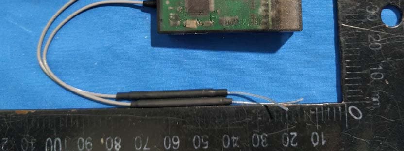
TZVRF209S
Mar 12, 2020Wireless Digital Model Remote Control Receiver
Equipment Class
DSS - Part 15 Spread Spectrum Transmitter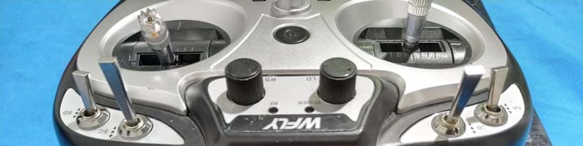
TZVET06
Mar 12, 2020Digital Proportion Model Radio Controller
Equipment Class
DSS - Part 15 Spread Spectrum Transmitter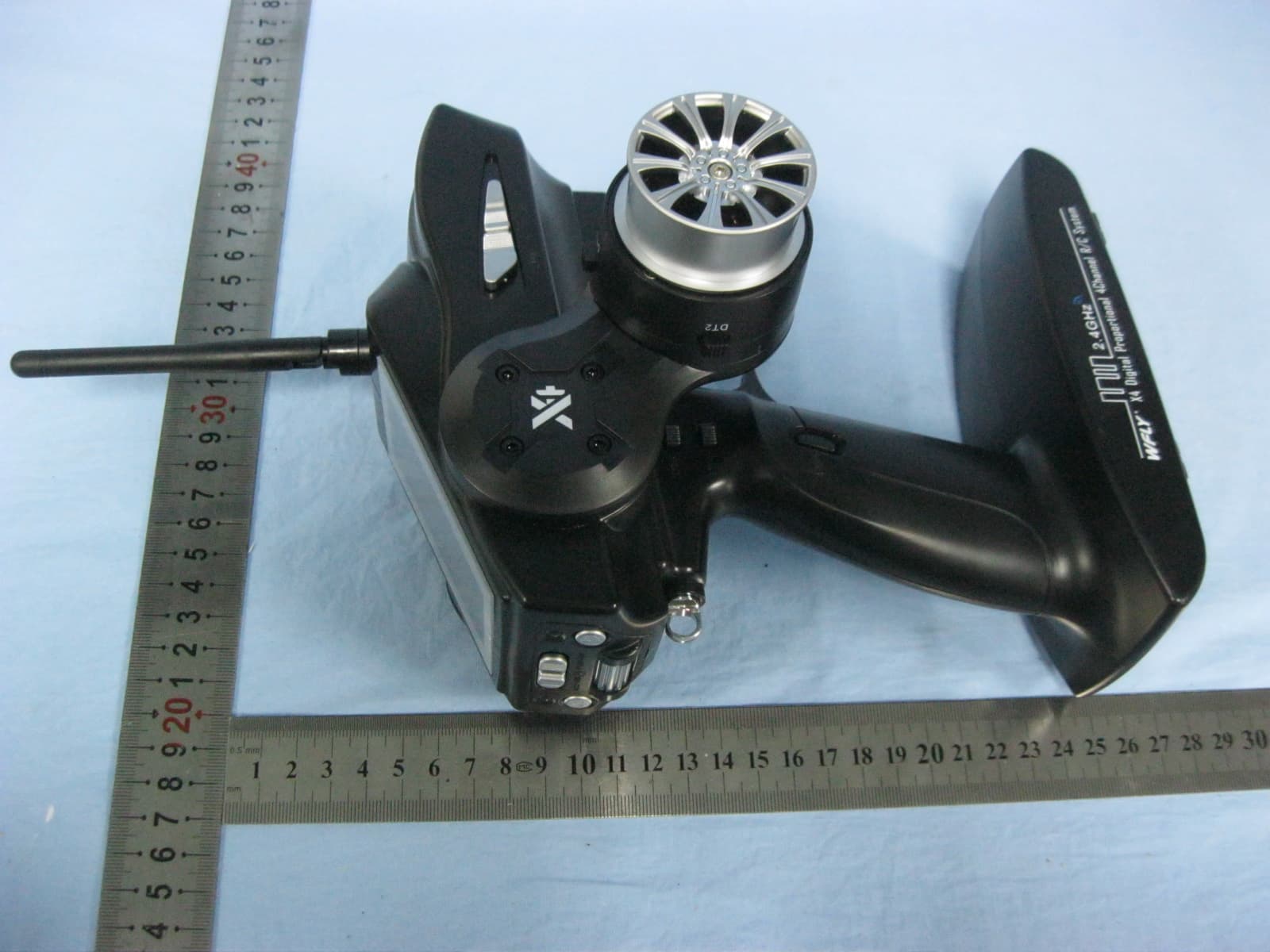
TZVX4
Dec 26, 2013DIGITAL PROPORTIONAL REMOTE CONTROLLER
Equipment Class
DSS - Part 15 Spread Spectrum Transmitter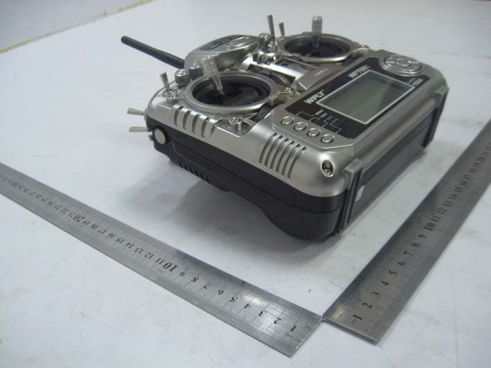
TZVWFT09II
Sep 05, 2011RADIO CONTROL SYSTEM
Equipment Class
DTS - Digital Transmission System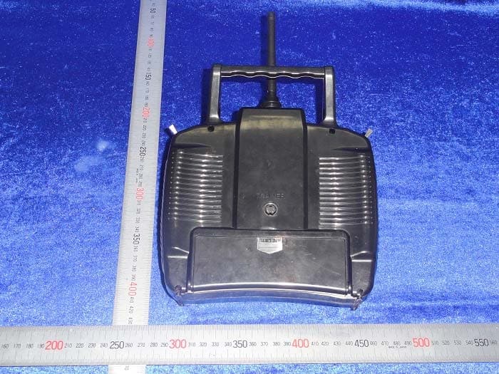
TZVWFT07
Sep 19, 2010RADIO CONTROL SYSTEM
Equipment Class
DXX - Part 15 Low Power Communication Device Transmitter