U28FUITE01Hearing Aid Module
Oticon A/S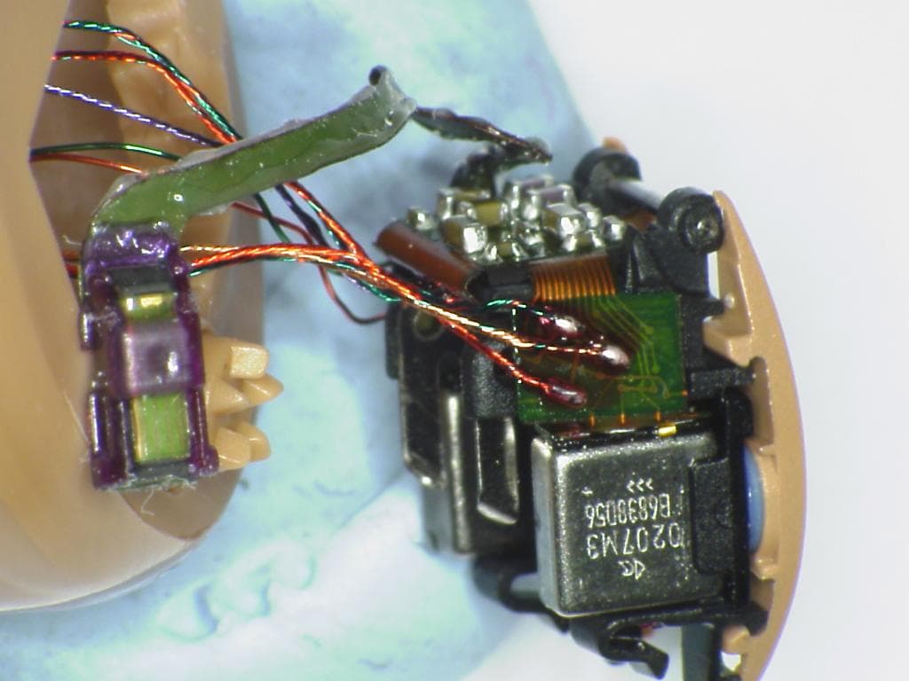
Click to zoom
Application Details
- Equipment Class
- DXX - Part 15 Low Power Communication Device Transmitter
- Date of Grant
- Mar 20, 2007
- Application Purpose
- Original Equipment
- Date of Application
- Mar 20, 2007
- Equipment Note
- Hearing Aid Module
- Frequency Range
- 3.84000000 - 3.84000000
- Company
- Oticon A/S
- Country
- Denmark
Documents & Files
Document Text
Text extracted from the exhibit documents filed with the FCC. Open a document above to read the original.
Users Manual
CIC, MIC, ITC, ITE INSTRUCTIONS FOR USE Preliminary Congratulations We at Oticon would like to take this opportunity to congratulate you on selecting the most advanced Hearing Instrument on the market today. These instructions will help you get the most out of the instrument and ensure their continued high performance. Carefully follow these instructions when using and maintaining them. Contents Instrument View CIC/MIC 5 Instrument View ITC 7 Instrument View ITE 9 Turning your instruments ON and OFF 11 Inserting your hearing instruments 12 Programs 13 Standby 16 Volume Control (Optional for ITE only) 17 Changing batteries 20 Telecoil (Optional) 22 Auto Phone (Optional) 23 Daily care of your hearing instrument 24 Using your hearing instrument 29 Common problems and their solutions 36 International Warranty 40 Warnings Yellow Pages Important Notice Please familiarise yourself with the entire contents of this booklet before using your hearing instruments. It contains instructions and important information about the use and handling of your hearing instruments and batteries. 2 Instrument View CIC/MIC Microphone opening Battery door Ventilation opening Sound outlet + wax protection system Ventilation opening Battery size: 10 5 Instrument View ITC Microphone opening Battery door Ventilation opening Ventilation opening Sound outlet + wax protection system Push-button (Optional) Battery size: 312 7 Battery size: 312 Instrument View ITE Microphone openings Push-button Sound outlet + wax protection system Ventilation opening Volume Control Wheel (Optional) Battery door 9 ON OFF 11 Turning your instruments ON and OFF Turn ON your hearing instrument by closing the battery door completely with the battery in place. When the battery door is closed the instrument will start up by playing a jingle. This indicates that the battery is working and the instrument is operating. Turn OFF your hearing instrument by opening the battery door with your finger nail. To preserve the battery, make sure your hearing instrument is switched off when you are not wearing it. Inserting your hearing instruments Place the tip of the hearing instrument in your ear canal (use your right hand to insert the right instrument and your left hand to insert the left instrument). Gently pull down your earlobe and push the hearing instrument into the ear canal, twisting slightly if necessary, following the natural contour of the ear canal. DO NOT use the battery door as a handle to insert or remove 12 13 Your hearing instruments may have a push-button for switch- ing between different programs. Push briefly on the button to activate the program switch. Programs (Optional) One beep, when you switch to program 1 Two beeps, when you switch to program 2 Three beeps, when you switch to program 3 Four beeps, when you switch to program 4 e ee eee eeee 14 15 Your hearing instrument can have up to 4 different programs. When switching between the different programs, your hearing instrument will beep. The number of beeps will indicate which program you are using. Below you can see a description of the programs available in your hearing instrument. Prg. 1: __________________________________ Prg. 2: __________________________________ Prg. 3: __________________________________ Prg. 4: __________________________________ Using 2 instruments For ease of use, the push button can be programmed to change to the equivalent program in the other instrument also, by using the wireless communication between the instruments. This is referred as binaural interchange. Binaural Interchangeable enabled You may ask your Hearing Care Professional about the set-up of your instrument. Your ITE instrument may have a volume control wheel. The Volume Control wheel can be turned with the tip of a finger and can be rotated infinitely both ways. 16 17 Standby (only installed with push-button) If your hearing instrument has a push-button, push the button for a minimum of 3 seconds to set the instrument in standby mode. To reactivate the instrument, push the button brieftly again. Use the standby function if you need to silence the instrument. PUSH 3 sec Volume Control (Optional for ITE only) Volume Control Wheel The Volume Control allows you to adjust the volume in specific listening situations to the level you feel comfortable with. To increase volume, turn the wheel forward. To decrease volume, turn the wheel towards the back of your head. When the hearing instrument is turned on, it starts up at a preferred volume level. When adjusting the volume control to the preferred level, this is indicated by a beep. Using 2 instruments For ease of use, the volume control wheel can be programmed to adjust the volume in the other instrument equivalently, by using the wireless communication between the instruments. This is referred as binaural interchange. Binaural Interchangeable enabled You may ask your Hearing Care Professional about the set-up of your instrument. 18 19 Changing batteries The correct battery size appears in the instrument overview in the first section of this document A worn out battery should be removed immediately. When the battery power is low, you will hear a series of short beeps. This indicates that it is time to change the battery. To replace the battery, follow these instructions: Open the battery door with your fi ngernail and remove the old battery. Remove the sticky label from the + side of the new battery. • • Insert the new battery with the marking faces the + sign printed on the battery door. Close the battery door. If you feel any resistance, you may have inserted the battery incorrectly. Reinsert the battery and try again. It will take a few seconds before the battery works to full capacity. To assist the handling of the batteries, the magnet placed at the end of the tool can be used. • • 20 21 23 The hearing instrument has a built-in telecoil. The telecoil is a receiver for audio signals transmitted from an inductive loop installation. The telecoil…
Text truncated - open the document above for the full version.
ID Label/Location Info
44 45 Waste from electronic equipment must be handled according to local regulations. 0543 ID: U28FUITE01 IC: 1350B-FUITE01 The hearing instrument contains a module with: The device complies with Part 15 of the FCC rules and RSS-210 of Industry Canada. Operation is subject to the following two conditions: 1. this device may not cause harmful interference 2. this device must accept any interference received, including interference that may cause undesired operation. Changes or modifications made to the equipment not expressly approved by Oticon may void the FCC’s authorization to operate the equipment. Oticon A/S 9, Kongebakken DK-2765 Smørum www.hear-it.org www.oticon.com
Test Report
CETECOM ICT Services GmbH Untertürkheimer Str. 6-10, 66117 Saarbruecken Phone: +49 (0) 681 598-0 Fax: -9075 RSC-Laboratory Phone: +49 (0) 681 598-0 Fax: -9075 Test report no.: 2-4458-02-06c/06 Date: 2007-02-26 Page 1 of 25 Recognized by the Federal Communications Commission Anechoic chamber registration no.: 90462 (FCC) Anechoic chamber registration no.: IC 3463A-1 TCB ID: DE 0001 Accredited by the German Accreditation Council DAR–Registration Number DAT-P-176/94-D1 Independent ETSI compliance test house ETSI Accredited Bluetooth ® Test Facility (BQTF) Test report no. : 2-4458-02-06c/06 Applicant : Oticon S/A Type : ITE Test Standard : FCC Part 15.247, 15.223 RSS-210 Issue 6 FCC ID : U28FUITE01 Certification No. IC : 1350B-FUITE01 The Bluetooth word mark and logos are owned by the Bluetooth SIG, Inc. and any use of such marks by Cetecom ICT is under license CETECOM ICT Services GmbH Untertürkheimer Str. 6-10, 66117 Saarbruecken Phone: +49 (0) 681 598-0 Fax: -9075 RSC-Laboratory Phone: +49 (0) 681 598-0 Fax: -9075 Test report no.: 2-4458-02-06c/06 Date: 2007-02-26 Page 2 of 25 Table of contents 1. ADMINISTRATIVE DATA ......................................................................................................................................3 1.1. ADMINISTRATIVE DATA OF THE TEST FACILITY..................................................................................................... 3 1.1.1 Identification of the testing laboratory ......................................................................................................... 3 1.1.2 Organizational items.....................................................................................................................................3 1.1.3 Applicant ́s details ........................................................................................................................................ 4 1.2 ADMINISTRATIVE DATA OF MANUFACTURER / MEMBER........................................................................................ 4 1.3 DESCRIPTION OF THE EQUIPMENT UNDER TEST (EUT) .......................................................................................... 5 1.3.1 EUT: Type, S/N etc. ......................................................................................................................................5 1.4 TEST SETUP........................................................................................................................................................... 6 1.5 TEST SPECIFICATIONS............................................................................................................................................ 6 2 STATEMENT OF COMPLIANCE .......................................................................................................................... 7 2.1 SUMMARY OF MEASUREMENT RESULTS................................................................................................................ 7 2.1.1 CFR 47 Part 15 Radio frequency devices ..................................................................................................... 7 3 MEASUREMENTS AND RESULTS ....................................................................................................................... 8 4 FCC PART 15 SUBPART C...................................................................................................................................... 9 4.1 Timing of the transmitter .................................................................................................................................. 9 4.2 Field strength of the fundamental § 15.209 (a) / 15.223............................................................................ 10 4.3 Field strength of the harmonics and the spurious § 15.209 (a) / 15.223 ...................................................... 12 4.4 Plots of measurements ....................................................................................................................................13 4.5 Receiver spurious emission (radiated)............................................................................................................ 15 4.6 Conducted Limits ............................................................................................................................................ 17 5 USED TESTEQUIPMENT ...................................................................................................................................... 18 6 ANNEX B: PHOTOGRAPHS OF TEST SITE ..................................................................................................... 21 7 ANNEX C: EXTERNAL PHOTOGRAPHS OF THE EQUIPMENT ................................................................ 23 8 ANNEX D: INTERNAL PHOTOGRAPHS OF THE EQUIPMENT.................................................................. 24 ANNEX 1: TECHNICAL PRODUCT DESCRIPTION CETECOM ICT Services GmbH Untertürkheimer Str. 6-10, 66117 Saarbruecken Phone: +49 (0) 681 598-0 Fax: -9075 RSC-Laboratory Phone: +49 (0) 681 598-0 Fax: -9075 Test report no.: 2-4458-02-06c/06 Date: 2007-02-26 Page 3 of 25 1. Administrative data 1.1. Administrative data of the test facility 1.1.1 Identification of the testing laboratory Company name: Cetecom ICT Services GmbH Address: Untertürkheimerstr. 6-10 D-66117 Saarbruecken Germany Laboratory accreditation: DAR-Registration No. DAT-P-176/94-D1 Bluetooth Qualification Test Facility (BQTF) Responsible for testing laboratory: Harro Ames Phone: +49 681 598 0 Fax: +49 681 598 9075 email: [email protected] ........................................................................................... Responsible for testing (Stefan Bös) 1.1.2 Organizational items Reference No.: 2-4458-02-06c/06 Order No.: Receipt of EUT: 2007-02-13 Date(s) of test: 2007-02-13 to 2007-02-14 Date of report: 2007-02-26 Number of report pages: 25 Number of diagram pages (annex): -------------------------------------------------…
Text truncated - open the document above for the full version.
Test Setup Photos
CETECOM ICT Services GmbH Untertürkheimer Str. 6-10, 66117 Saarbruecken Phone: +49 (0) 681 598-0 Fax: -9075 RSC-Laboratory Phone: +49 (0) 681 598-0 Fax: -9075 Test report no.: 2-4458-02-06c/06 Date: 2007-02-26 Page 21 of 25 6 Annex B: Photographs of Test site Photo 1: Radiated Emissions (ITE) CETECOM ICT Services GmbH Untertürkheimer Str. 6-10, 66117 Saarbruecken Phone: +49 (0) 681 598-0 Fax: -9075 RSC-Laboratory Phone: +49 (0) 681 598-0 Fax: -9075 Test report no.: 2-4458-02-06c/06 Date: 2007-02-26 Page 22 of 25 Photo 2: Radiated Emissions (ITE)
Contact Information
Applicant
Per Klaus Nielsen(Certification Manager)
Test Firm
cetecom advanced GmbHGerald Schmidt
Technical Specifications
| # | Rule Parts | Frequency Range | Power Output |
|---|---|---|---|
| 1 | 15C | 3.84 MHz - 3.84 MHz | - |
Other Applications from Oticon A/S
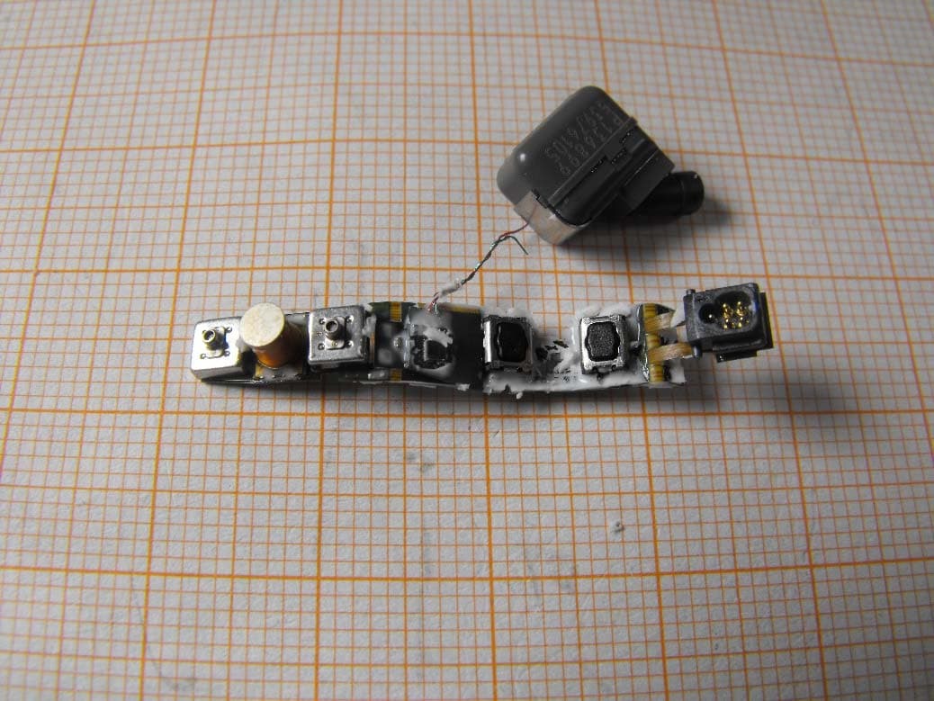
U28FU2BTEPP
Jun 29, 2015hearing instrument with short range low power wireless radio
Equipment Class
DXX - Part 15 Low Power Communication Device Transmitter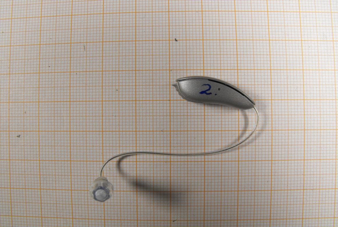
U28FU2DRIT
Aug 10, 2014Hearing Aid Module
Equipment Class
DXX - Part 15 Low Power Communication Device Transmitter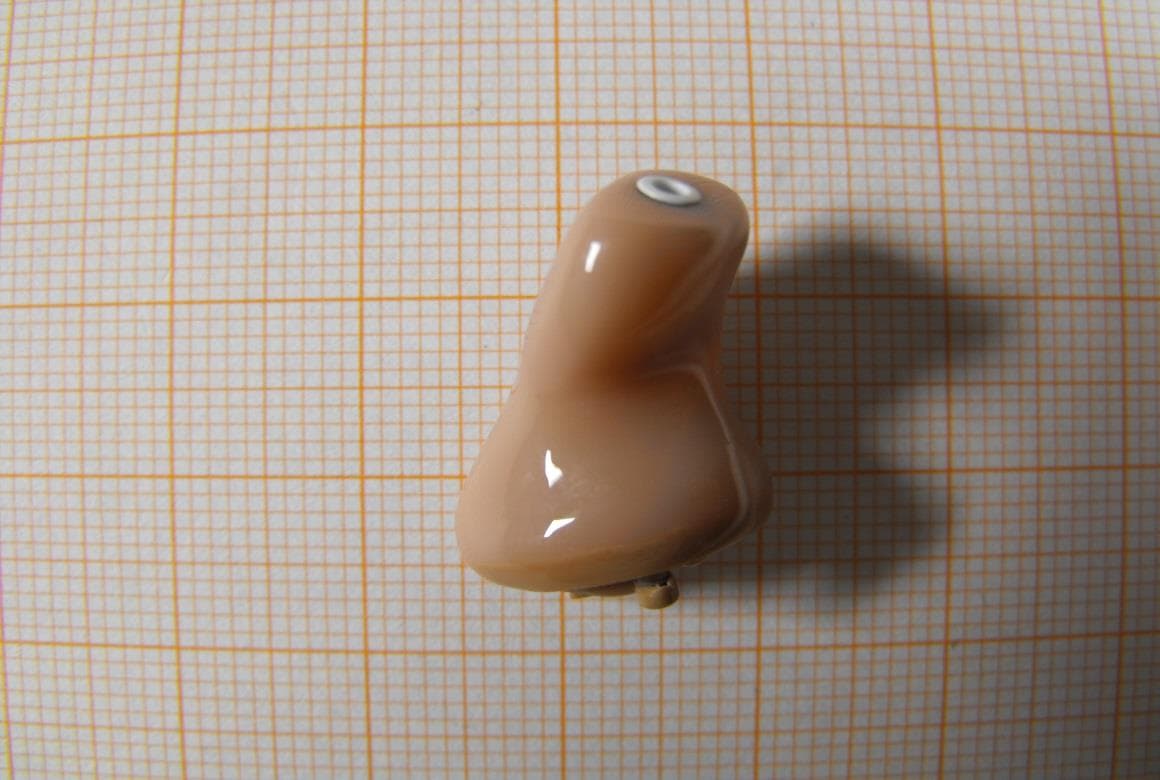
U28FU2CICWL
Jun 22, 2014Hearing Aid
Equipment Class
DXX - Part 15 Low Power Communication Device Transmitter
U28WLPS10
Apr 09, 2014WLP Special
Equipment Class
DXX - Part 15 Low Power Communication Device Transmitter
U28TVBOX03
Aug 19, 2013TV Adapter 2.0
Equipment Class
DSS - Part 15 Spread Spectrum Transmitter