U28FURIT04Hearing Aid module
Oticon A/S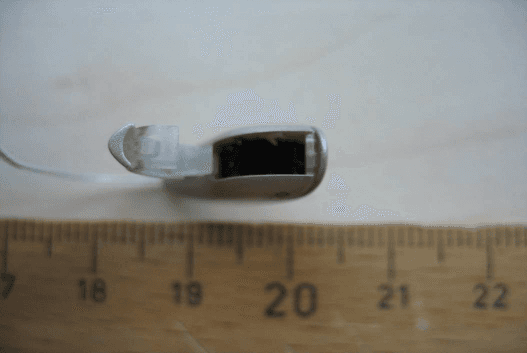
Click to zoom
Application Details
- Equipment Class
- DXX - Part 15 Low Power Communication Device Transmitter
- Date of Grant
- Jul 24, 2011
- Application Purpose
- Original Equipment
- Date of Application
- Jul 21, 2011
- Equipment Note
- Hearing Aid module
- Frequency Range
- 3.80000000 - 3.80000000
- Company
- Oticon A/S
- Country
- Denmark
Documents & Files
Document Text
Text extracted from the exhibit documents filed with the FCC. Open a document above to read the original.
Users Manual
PEOPLE FIRST Oticon A/S Kongebakken 9 DK ‐ 2765 Smørum www.oticon.com Main +45 39 17 71 00 Fax +45 39 27 79 00 Denmark CVR ‐ no. 42334219 1 Oticon Radio Model - Quick Installation Guide Radio Model Name: RITE 4 The RITE 4 radio model is a low power, inductive radio transceiver wo rking at 3.84 MHz consisting of an RF Engine Block (incl. DSP, radio & memory), antenna coil, motherboard (incl. small passive components) and intended to be installed as a module into Oticon wireless hearing aid de vices only. The module also has all voltage regulators included inside the engi ne block. The module requires a battery, one or two microphones on a flex PCB and a speaker to be attached and must be mounted in an external plastic shell. It is possible for aut horized personnel only to program the module through a flex I/O. Th e module is depicted below: RITE 4 Radio Model (seen from the top side) RITE 4 Radio Model (seen from the bottom) RF Engine Bl ock Antenna Motherboard Battery - Battery + Program flex I/O Speaker unit connectors Mic flex PEOPLE FIRST Oticon A/S Kongebakken 9 DK ‐ 2765 Smørum www.oticon.com Main +45 39 17 71 00 Fax +45 39 27 79 00 Denmark CVR ‐ no. 42334219 2 Oticon Radio Model - Quick Installation Guide Radio Model Name: RITE 4 RITE 4 Radio Model (seen from the side) FCC ID: U28FURIT04 IC: 1350B-FURIT04 NOTICE: This device complies with Part 15 of the F CC Rules and with RSS- 210 of Industry Canada. Operation is subject to th e following two conditions: (1) This device may not cau se harmful interference, and (2) This device must accept any interference received, including interference that may cause undesired operation.
Users Manual
InstructIons for userItE thank you Thank you for choosing our product as a means to better hearing. To support your efforts, we have put great care and attention into making sure that your new hearing instruments are of the highest quality and that they are easy to use and maintain. Your new hearing instruments are designed to amplify and transmit sound to your ears and thereby improve your hearing in most situations. The amplification is uniquely adjusted and optimized to your personal hearing capabilities by the fitting performed by your Hearing Care Professional. To meet your needs, various functions may be configured to your hearing instruments. The actual configuration of your instruments may be marked (checked off) by your Hearing Care Professional in relevant sections of this manual. You may also see the last page for a complete overview of all functions configured to your hearing instrument(s). We recommend that you read this manual carefully to achieve the maximum benefit of your new hearing instruments. If you have any questions regarding the use or maintenance of your hearing instruments, please contact your Hearing Care Professional. Indications for use The intended use of your hearing instrument is to amplify and transmit sound to the ear and hereby compensate for impaired hearing. Your hearing instrument is indicated for: hearing losses within the mild-to-severe range. 3 contents Instrument view 7 Warnings 8 Activating the hearing instrument for the first time 16 Changing batteries 17 Turning your instruments ON and OFF 19 Left/Right ear marking 20 Putting on your instrument 21 Programs (Optional) 22 Volume control (Optional) 24 Caring for your hearing instrument 25 Daily maintenance with mold 28 Daily maintenance with domes 30 Seven easy steps to better hearing 35 Common problems and their solutions 40 Wireless accessories 42 International Warranty 43 7 Instrument view I m p o rta n t no tIc E Please familiarize yourself with the entire contents of this booklet before using your hearing instru ments. It contains instructions and important informa tion about the use and handling of your hearing instru ments and batteries. Cell Phone 45 Technical information 47 Settings overview of your hearing instrument 50 Speaker unit Sound outlet Wax protection Microphone openings Battery door Battery size: 10 Your ear piece Open dome: 6mm 8mm 10mm Plus dome Power dome: 6mm 8mm 10mm 12mm Micro mold 98 Warnings You should familiarize yourself fully with the following general warnings and the entire contents of this booklet before using your hearing instrument. Usage of hearing instruments • Hearing instruments should be used only as directed and adjusted by your Hearing Care Professional. Misuse can result in sudden and permanent hearing loss. • Never allow others to wear your hearing instrument as incorrect/wrongful usage could cause permanent damage to their hearing. Choking Hazards • Hearing instruments, their parts, and batteries are not toys and should be kept out of reach of children and anyone who might swallow these items or otherwise cause injury to themselves. • Never change the battery or adjust the controls of the hearing instruments in front of infants, small children or people with learning difficulties. • Discard batteries carefully in a place where infants, small children or people with learning difficulties cannot reach them • Batteries have occasionally been mistaken for pills. Therefore check your medicine carefully before swallowing any pills. • Never put your hearing instrument or batteries in your mouth for any reason, as they are slippery and could be swallowed by accident. Battery use • Always use batteries recommended by your Hearing Care Professional. Batteries of low quality may leak and cause bodily harm. • Never attempt to recharge your batteries. They may explode and cause serious injury. • Never dispose of batteries by burning them. There is a risk that they will explode and cause serious injury. Dysfunction in hearing instruments • Hearing instruments may stop functioning, for instance if the batteries have expired or if the tubing is blocked by moisture or earwax. You should be aware of this possibility, in particular when you are in traffic or otherwise dependent on warning sounds. Active Implants • Oticon shows caution and advises following recommended guidelines of manufactur- ers of implantable defibrillators and pacemakers regarding use of mobile phones. • If you wear an active implant, then keep the hearing instruments more than 15 cm away from the implant e.g. do not carry them in a breast pocket. If you have an active brain implant, please contact the manufacturer of your implantable device for informa- tion about the risk of disturbance. • The MultiTool has a built-in magnet. If you have an implantable device, such as pacemakers or defibrillators, the MultiTool should not be carried in a breast pocket or near the chest. Explosives • The power source in your hearing instrument has insufficient energy to cause fire in normal conditions of use. The hearing instrument has not been tested for compliance with international standards concerning explosive atmospheres. It is recommended not to use your hearing instruments in areas where there is a danger of explosions. X-ray, CT, MR, PET scanning and electrotherapy • Remove your hearing instrument for example during X-ray, CT / MR / PET scanning, electrotherapy or surgery as your hearing instruments may be damaged when exposed to strong fields. Possible side effects • Hearing instruments or ear molds may cause an accelerated accumulation of ear wax. • The otherwise non-allergenic materials used in hearing instruments may in rare cases cause a skin irritation or any other unusual condition. Please, seek consultation with a physician if these conditions occur. Interference • Your hearing instrument has been thoroughly tested for interference, according to the most stringent international standards. However, …
Text truncated - open the document above for the full version.
Attestation Statements
PEOPLE FIRST www.oticon.com Main +45 39 17 71 00 Fax +45 39 27 79 00 CVR‐no. 42334219 Oticon A/S Kongebakken 9 DK‐2765 Smørum Denmark Federal Communication Commission Equipment Authorization Division, Application Processing Branch 7435 Oakland Mills Road Columbia, MD 21046 20 th of July 2011 Oticon Fusion 2 based wireless RITE 4 module FCC ID: U28FURIT04 Modular Approval Request We would like to approve the above product by certification as a Limited Single-Modular Transmitter in accordance with FCC Part 15 about unlicensed Radio Frequency Devices in paragraph §15.212 for Modular Transmitters. The requirements of the Modular Transmitter paragraph §15.212 are met as follows: 1. The radio module has only got RF shielding of a major part of the RF circuit, not completely. The product is also constrained to be used solely by Oticon A/S and its daughter companies or sold to Original Equipment Manufactures (OEM) of Hearing Instruments only. Therefore we apply for a Limited Modular Approval. The module is a fully integrated and inseparable part of an amplifier module for Rite style hearing aids. Therefore the radio module alone cannot be used by end users. The behaviour of the wireless module is locked by the design and can only be changed by Oticon A/S, so the compliance of the end product is always ensured. (See further descriptions in the radio model installation guide and/or user manual) 2. The amplifier module includes buffer stages for its external data/programming inputs. 3. The wireless part of the engine block inside the amplifier module shares the power supply with the digital signal processing (DSP) part of the engine block. Therefore we apply for a Limited Modular Approval with the same argumentation as in point 1. 4. The radio part of the amplifier module has only an integral and permanently attached antenna. 5. The amplifier module was tested in a stand‐alone configuration, but mounted inside a Hearing Aid plastic shell, as can be seen in anneces A‐C of the CETECOM Test Report No. 1‐3041‐01‐02/11. The module fulfils Part 15 emission limits without any additional RF shielding. 6. The size of the whole amplifier module (engine block and motherboard) is less than 1/4 inch so the labelling information is located in the user manual and radio model installation guide. 7. The amplifier module is compliant with all applicable FCC rules. Maintenance of compliance is always ensured as only Oticon A/S is authorized to alter the antenna or other wireless related behaviours. 8. The amplifier module is compliant with all applicable RF exposure requirements. Maintenance of compliance is always ensured as only Oticon A/S is authorized to alter the antenna or other wireless related behaviours. If you have any questions, please feel free to contact us at the address shown below Sincerely, Lars Bresler, QM-manager Oticon A/S Kongebakken 9 2765 Smorum - DK-Denmark Phone: +45 3913 7100
Cover Letter(s)
PEOPLE FIRST CONFIDENTIALITY REQUEST for Certification Service in USA Federal Communication Commission Equipment Authorization Division, Application Processing Branch 7435 Oakland Mills Road Columbia, MD 21046 July 20, 2011. TO WHOM IT MAY CONCERN Pursuant to Paragraphs §0.457 and 0.459 of the Commission’s Rules (47 C.F.R.) and Section §552(b)(4) of the Freedom of Information Act, we request confidentiality for the following products: FCC ID Model name U28FURIT04 RITE 4 For the product stated above, we request that the following information be held confidential: 1. Circuit diagrams, Bill-Of-Material (BOM), and PCBs submitted as Equipment Authorization Electronic Filing attachment: “BOM”, "schematics” and “layouts”. 2. Block diagram submitted as Equipment Authorization Electronic Filing attachment: “block diagram”. 3. Operational description submitted as Equipment Authorization Electronic Filing attachment: “operational description” and/or “product description”. The above exhibits contain our trade secrets and proprietary information that could be of benefit to our competitors. If you have any questions, please feel free to contact me at the address shown below. Sincerely, Lars Bresler, QM-manager Oticon A/S Kongebakken 9 2765 Smorum DK-Denmark Phone: +45 3913 7100
Cover Letter(s)
PEOPLE FIRST SHORT-TERM CONFIDENTIALITY REQUEST Federal Communication Commission Equipment Authorization Division, Application Processing Branch 7435 Oakland Mills Road Columbia, MD 21046 July 20, 2011. TO WHOM IT MAY CONCERN Pursuant to the recent upgrade to the Office of Engineering and Technology’s (OET) Equipment Authorization System on 6/15/04 (ref. DA 04 –1705), Oticon A/S requests temporarily confidentiality for the following product: FCC ID Number Product Title/Model U28FURIT04 RITE 4 For the product stated above, we request that the following information be held confidential: 1. External and Internal Photographs 2. Test Setup Photos 3. User Manual We request this confidentiality on the basis of ensuring that business sensitive information remains confidential for 100 days. If you have any questions, please feel free to contact me at the address shown below. Sincerely, Lars Bresler, QM-manager Oticon A/S Kongebakken 9 2765 Smorum DK-Denmark Phone: +45 3913 7100
External Photos
Test report no.: 1-3041-01-02/11 2011-06-28 Page 32 of 41 An ne x B Ex te rna l ph ot ogra phs o f the E UT Photo documentation: Photo 1: Photo 2: Test report no.: 1-3041-01-02/11 2011-06-28 Page 33 of 41 Photo 3: Photo 4: Test report no.: 1-3041-01-02/11 2011-06-28 Page 34 of 41 Photo 5: Photo 6:
ID Label/Location Info
PEOPLE FIRST Oticon A/S Kongebakken 9 DK ‐ 2765 Smørum www.oticon.com Main +45 39 17 71 00 Fax +45 39 27 79 00 Denmark CVR ‐ no. 42334219 1 Oticon Radio Model - Label Info - Extract from Installation Guide Radio Model Name: RITE 4 FCC ID: U28FURIT04 IC: 1350B-FURIT04 NOTICE: This device complies with Part 15 of the F CC Rules and with RSS- 210 of Industry Canada. Operation is subject to th e following two conditions: (1) This device may not cau se harmful interference, and (2) This device must accept any interference received, including interference that may cause undesired operation.
Internal Photos
Test report no.: 1-3041-01-02/11 2011-06-28 Page 35 of 41 An ne x C Inte r na l p ho to gra phs o f the E UT Photo documentation: Photo 1: Photo 2: Test report no.: 1-3041-01-02/11 2011-06-28 Page 36 of 41 Photo 3: Photo 4: Test report no.: 1-3041-01-02/11 2011-06-28 Page 37 of 41 Photo 5: Photo 6: Test report no.: 1-3041-01-02/11 2011-06-28 Page 38 of 41 Photo 7: Photo 8: Test report no.: 1-3041-01-02/11 2011-06-28 Page 39 of 41 Photo 9: Photo 10: Test report no.: 1-3041-01-02/11 2011-06-28 Page 40 of 41 Photo 11: Photo 12:
Test Report
2011-07-25 Page 1 of 25 TEST REPORT Test report no.: 1-3041-01-02/11-A Testing laboratory Applicant CETECOM ICT Services GmbH Untertuerkheimer Strasse 6 – 10 66117 Saarbruecken / Germany Phone: + 49 681 5 98 - 0 Fax: + 49 681 5 98 - 9075 Internet: http://www.cetecom.com e-mail: [email protected] Accredited test laboratory: The test laboratory (area of testing) is accredited according to DIN EN ISO/IEC 17025 DAkkS registration number: D-PL-12076-01-01 Area of Testing: Radio/Satellite Communications Oticon A/S Kongebakken 9 2765 Smørum / DENMARK Phone: +45 39 17 71 00 Fax: -/- Contact: Jørgen Peter Hanuscheck e-mail: [email protected] Phone: +45 39 13 85 38 Manufacturer Oticon A/S Kongebakken 9 2765 Smørum / DENMARK Test standard/s 47 CFR Part 15 Title 47 of the Code of Federal Regulations; Chapter I Part 15 - Radio frequency devices RSS - 210 Issue 8 Spectrum Management and Telecommunications - Radio Standards Specification Low-power Licence-exempt Radiocommunication Devices (All Frequency Bands): Category I Equipment RSS – GEN Issue 3 General Requirements & Information for the Certification of Radio Apparatus under test standards. For further applied test standards please refer to section 3 of this test report. Test item Kind of test item: Hearing aid Model name: Rite 4 FCC ID: U28FURIT04 IC: 1350B-FURIT04 Frequency: 3.8 MHz Power supply: 1.40 V DC by zinc - air battery / power supply Temperature range: 0 °C to +35 °C This test report is electronically signed and valid without handwriting signature. For verification of the electronic signatures, the public keys can be requested at the testing laboratory. Test performed: Test report authorised: p. o. Marco Bertolino Stefan Bös Test report no.: 1-3041-01-02/11-A 2011-07-25 Page 2 of 25 1 Table of contents 1 Table of contents ............................................................................................................................................ 2 2 General information ....................................................................................................................................... 2 2.1 Notes ..................................................................................................................................................... 2 2.2 Application details ............................................................................................................................... 3 3 Test standard/s ............................................................................................................................................... 3 4 Test environment ............................................................................................................................................ 3 5 Test item .......................................................................................................................................................... 4 6 Test laboratories sub-contracted ................................................................................................................. 4 7 Summary of measurement results ............................................................................................................... 5 8 RF measurement testing................................................................................................................................ 6 8.1 Description of test setup .................................................................................................................... 6 8.1.1 Radiated measurements............................................................................................................. 6 8.1.2 Conducted measurements.......................................................................................................... 7 8.2 Additional comments .......................................................................................................................... 7 8.3 RSP100 test report cover sheet / performance test data ................................................................ 8 9 Measurement results ...................................................................................................................................... 9 9.1 Timing of the transmitter .................................................................................................................... 9 9.2 Bandwidth of the modulated carrier ................................................................................................ 10 9.3 Field strength of the fundamental ................................................................................................... 12 9.4 Fieldstrength of the harmonics and spurious ................................................................................ 14 9.5 Receiver spurious emissions ........................................................................................................... 18 9.6 Conducted limits ............................................................................................................................... 22 10 Test equipment and ancillaries used for tests ................................................................................... 23 Annex A Document history .......................................................................................................................... 25 Annex B Further information ........................................................................................................................ 25 2 General information 2.1 Notes Test report no.: 1-3041-01-02/11-A 2011-07-25 Page 3 of 25 The test results of this test report relate exclusively to the test item specified in this test report. CETECOM ICT Services GmbH does not assume responsibility for any conclusions and generalisations drawn from the test results with regard to other specimens or samples of the type of the equipment represented by the test item. The test report may only be reproduced or published in full.…
Text truncated - open the document above for the full version.
Test Setup Photos
Test report no.: 1-3041-01-02/11 2011-06-28 Page 25 of 41 An ne x A Pho tog ra phs o f t h e te s t s e tu p Photo documentation: Photo 1: chamber C Photo 2: chamber C Test report no.: 1-3041-01-02/11 2011-06-28 Page 26 of 41 Photo 3: chamber C Photo 4: chamber C Test report no.: 1-3041-01-02/11 2011-06-28 Page 27 of 41 Photo 5: chamber C Photo 6: chamber C Test report no.: 1-3041-01-02/11 2011-06-28 Page 28 of 41 Photo 7: chamber C Photo 8: chamber C Test report no.: 1-3041-01-02/11 2011-06-28 Page 29 of 41 Photo 9: chamber C Photo 10: chamber C Test report no.: 1-3041-01-02/11 2011-06-28 Page 30 of 41 Photo 11: chamber F Photo 12: chamber F Test report no.: 1-3041-01-02/11 2011-06-28 Page 31 of 41 Photo 13: chamber F Photo 14: chamber F
Contact Information
Applicant
Per Klaus Nielsen(Certification Manager)
Test Firm
cetecom advanced GmbHGerald Schmidt
Technical Specifications
| # | Rule Parts | Frequency Range | Power Output |
|---|---|---|---|
| 1 | 15C | 3.8 MHz - 3.8 MHz | - |
Other Applications from Oticon A/S
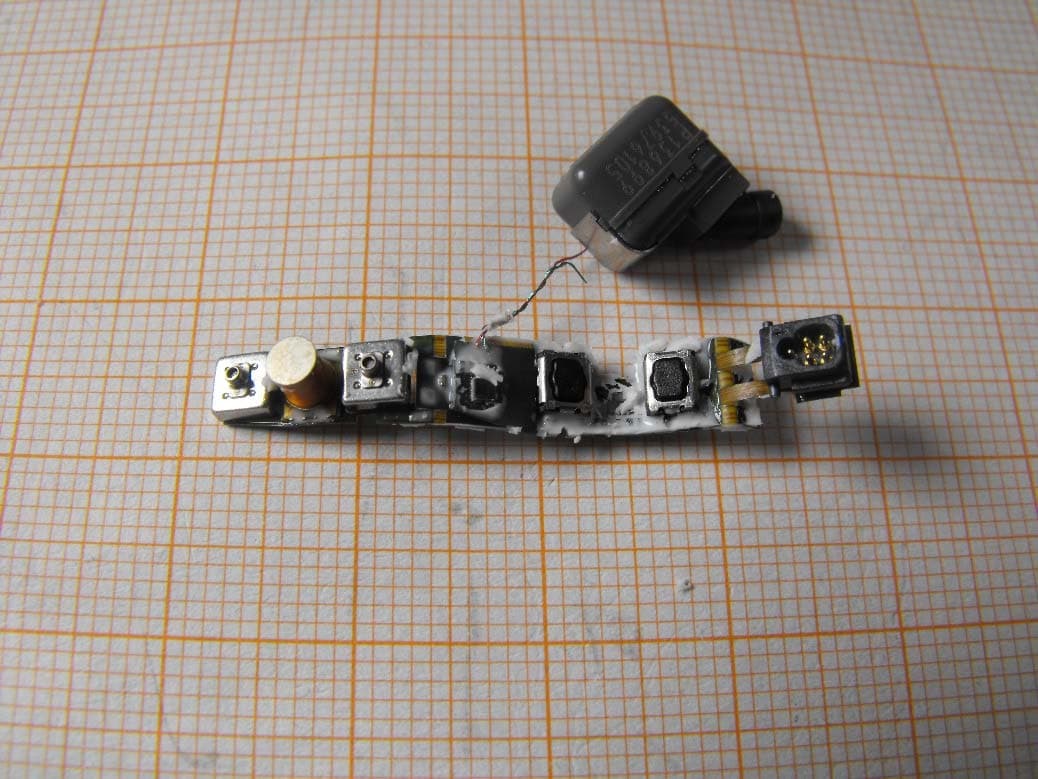
U28FU2BTEPP
Jun 29, 2015hearing instrument with short range low power wireless radio
Equipment Class
DXX - Part 15 Low Power Communication Device Transmitter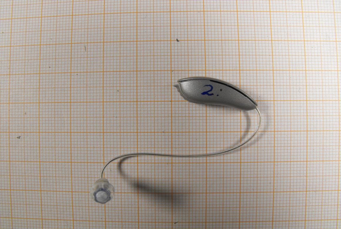
U28FU2DRIT
Aug 10, 2014Hearing Aid Module
Equipment Class
DXX - Part 15 Low Power Communication Device Transmitter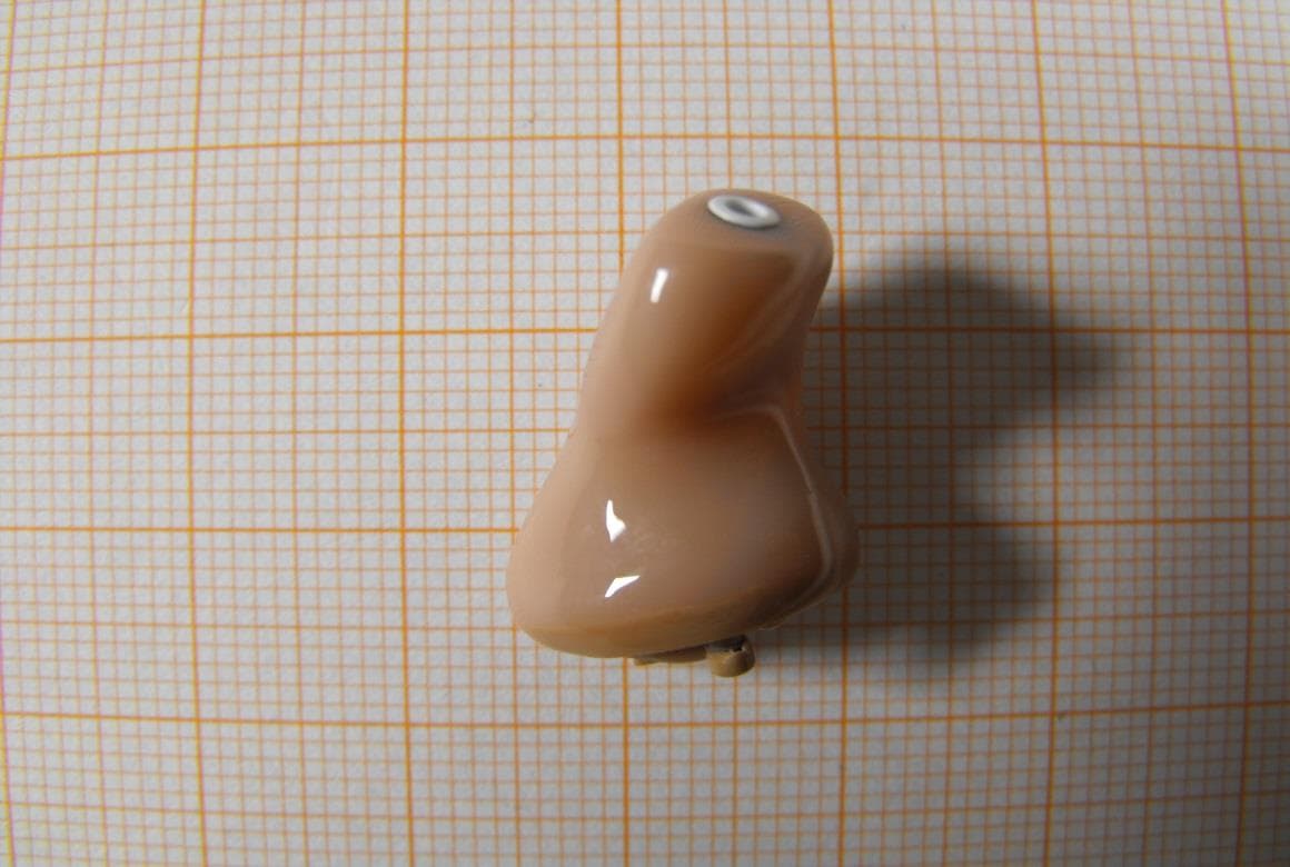
U28FU2CICWL
Jun 22, 2014Hearing Aid
Equipment Class
DXX - Part 15 Low Power Communication Device Transmitter
U28WLPS10
Apr 09, 2014WLP Special
Equipment Class
DXX - Part 15 Low Power Communication Device Transmitter
U28TVBOX03
Aug 19, 2013TV Adapter 2.0
Equipment Class
DSS - Part 15 Spread Spectrum Transmitter