U2BRL036T001ADigital Proportional R/C System
Radiolink Electronic Limited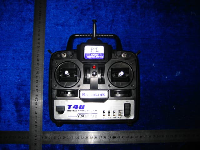
Click to zoom
Application Details
- Equipment Class
- TNB - Licensed Non-Broadcast Station Transmitter
- Date of Grant
- Mar 26, 2007
- Application Purpose
- Original Equipment
- Date of Application
- Mar 26, 2007
- Equipment Note
- Digital Proportional R/C System
- Frequency Range
- 72.01000000 - 72.99000000
- Company
- Radiolink Electronic Limited
- Country
- China
Documents & Files
Document Text
Text extracted from the exhibit documents filed with the FCC. Open a document above to read the original.
Users Manual
RADIOLINK DIGITAL PROPORTIONAL R/C SYSTEM OPERATING INSTRUCTIONS Before use please read these instructions completely 1 Introduction to the RL036T radio Thank you for purchasing Radiolink RL036T-001A four channel digital radio system it is a good quality radio and can be used in electric helicopter, engine aircraft, electric park-flying. It is important that you care fully read the manual before operate your moder . Note: The manufacturer is not responsible for any radio or TV interference caused by unauthorized modifications to this equipment. Such modifications could void the user authority to operate equipment. 2 RL036T TRANSMITTER ` Aileron trim Throttle actuator /elevator aileron stick. Elevator/ Rudder stick. Throttle actuator curve trim big and small rudder switch Drillmaster switch Throttle actuator trim pitch of screws trim Undercarriage switch 3D switch Antenna power and low battery display Hook Elevator trim Rudder trim On/off Switch Rudder positive and negative phase switch Throttle actuator positive and negative phase switch Aileron positive and negative phase switch Elevator positive and negative phase switch On/off Switch Rudder positive and negative phase switch Aileron positive and negative phase switch Elevator positive and negative phase switch Throttle actuator positive and negative phase switch antenna handgrip Drillmaster switch 3D switch Trainer cord jack Battery Book cover battery storehouse (8pcs AA 1.5V Charging jack 3 TRANSMITTER OPERATION LEFTRIGHT Aileron operation When the aileron stick is moved to the right,the right aileron is raised and the left aileron is lowered.relative to the direction of flight and the plane turns to the right.when the aileron stick is moved to the left.The ailerons move in the opposite direction DOWN UP Elevator operation When the elevator stick is pulled back,the tail elevator is raised and the tail of the plane is forced down.the air floe applied to the wings is changed.the lifting force is increased,and the plane climbs(up operation) when the elevator stick is pushed forward,the elevator is lowered the tail of the please is forced up.the air flow applied to the wings is changed.the lifting force is do creased and the plane dives(doen operation) HIGH LOW Throttle operation When the throttle stick is pulled back,the engine throttle lever arm moves to the slow side,when the throttle stick is pushed forward, the throttle lever arm moves to the high side. LEFT RIGHT Rudder operation When the rudder stick is moved to the right,the rudder moves to the right,and the nose points to the right,relative to the direction of flight.When the rudder stick is moved to the left,the rudder moves the left and the direction of travel of the plane changs. 4 CRYSTAL The crystal is soldered on PCB and cann’t be replaced by other type of crystal. 5 precautions during flight a) Do not fly simultaneously on the same frequency.Interference may cause acrash. *Use of the same frequency will cause Interference even if the modulation method(FM,PCM) is different. b) Do not fly in rainy or windy days water will penetrate into the transmitter and cause faulty operation,or loss of control,and cause acrash. c) Extend the antenna to its full length. If the antenna is too short, the effective range of the radio waves will become shorter.
ID Label/Location Info
FCC ID: U2BRL036T001A This device complies with part 95 of the FCC rules. Proposed Label Location on EUT FCC ID Label Location
Operational Description
Operation Description RL036T-001A transmitter is composed of signal generator pulse modulator and signal amplifier. pulse modulator signal be output by pint of MCU RL036T,adjusting CH1CH4 makes pules width change in 1.0~ 2.0ms ,it is achieved to proportional control. pules signal be adjusted by Q11,Q10,Q2,Q5,then is send to carry frequency OSC circuit to form FM modulation.the FM signal be amplified by Q7 ,Q8.finally be send out in sky by antenna.
Test Report
ISO/IEC17025 Accredited Lab. Report No: FCC0702003 File reference No: 2007-02-09 Applicant: Radiolink Electronic Limited Product: transmitter Model No: RL036T-001A Trademark: RL Test Standards: FCC 47 CFR PART 95 SUBPART C Test result: It is herewith confirmed and found to comply with the requirements set up by ANSI C63.4&FCC Part 95 Subpart C, regulations for the evaluation of electromagnetic compatibility Approved By Jack Chung Manager Dated: Feb 09,2007 Results appearing herein relate only to the sample tested The technical reports is issued errors and omissions exempt and is subject to withdrawal at SHENZHEN TIMEWAY TECHNOLOGY CONSULTING CO LTD 5/F,Block 4, Anhua Industrial Zone.,No.8 TaiRan Rd.CheGongMiao,FuTian District, Shenzhen,CHINA. Tel (755) 83448688 Fax (755) 83442996 Report No: 0702003 Page 2 of 25 Date: 2007-02-09 TEST REPORT The report refers only to the sample tested and does not apply to the bulk. This report is issued in confidence to the client and it will be strictly treated as such by the Shenzhen Timeway Technology Consulting Co .,Ltd. It may not be reproduced rather in its entirety or in part and it may not be used for adverting. The client to whom the report is issued may, however, show or send it . or a certified copy there of prepared by the Shenzhen Timeway Technology Consulting co .,Ltd to his customer. Supplier or others persons directly concerned. Shenzhen Timeway Technology Consulting co .,Ltd will not, without the consent of the client enter into any discussion of correspondence with any third party concerning the contents of the report. In the event of the improper use of the report. The Shenzhen Timeway Technology Consulting co .,Ltd reserves the rights to withdraw it and to adopt any other remedies which may be appropriate. Special Statement: The testing quality ability of our laboratory meet with "Quality Law of People's Republic of China" Clause 19. The testing quality system of our laboratory meet with ISO/IEC-17025 requirements, which is approved by CNAL. This approval result is accepted by MRA of APLAC. Our test facility is recognized, certified, or accredited by the following organizations: CNAL-LAB Code: L2292 The EMC Laboratory has been assessed and in compliance with CNAL/AC01:2002 accreditation criteria for testing Laboratories (identical to ISO/IEC 17025:1999 General Requirements) for the Competence of testing Laboratories. FCC-Registration No.: 899988 The EMC Laboratory has been registered and fully described in a report filed with the (FCC) Federal Communications commission. The acceptance letter from the FCC is maintained in our files. Registration No.: 899988. IC- Registration No.: IC5205 The EMC Laboratory has been registered and fully described in a report filed with the (IC) Industry Canada. The acceptance letter from the IC is maintained in our files. Registration IC No.: 5205. Report No: 0702003 Page 3 of 25 Date: 2007-02-09 TEST REPORT The report refers only to the sample tested and does not apply to the bulk. This report is issued in confidence to the client and it will be strictly treated as such by the Shenzhen Timeway Technology Consulting Co .,Ltd. It may not be reproduced rather in its entirety or in part and it may not be used for adverting. The client to whom the report is issued may, however, show or send it . or a certified copy there of prepared by the Shenzhen Timeway Technology Consulting co .,Ltd to his customer. Supplier or others persons directly concerned. Shenzhen Timeway Technology Consulting co .,Ltd will not, without the consent of the client enter into any discussion of correspondence with any third party concerning the contents of the report. In the event of the improper use of the report. The Shenzhen Timeway Technology Consulting co .,Ltd reserves the rights to withdraw it and to adopt any other remedies which may be appropriate. Test Report Conclusion Content 1.0 General Details ............................................................................................... 4 1.1 Test Lab Details................................................................................................ 4 1.2 Applicant Details.............................................................................................. 4 1.3 Description of EUT ........................................................................................... 4 1.4 Submitted Sample.............................................................................................. 4 1.5 Test Duration.................................................................................................... 4 1.6 Test Uncertainty................................................................................................ 5 1.7 Test By.......................................................................................................... 5 2.0 List of Measurement Equipment......................................................................... 5 3.0 Technical Details............................................................................................. 7 3.1 Summary of Test Results..................................................................................... 7 3.2 Test Standards.................................................................................................. 7 4.0 EUT Modification............................................................................................. 7 5.0 Test Result.......................................................................................................................... 8 5.1 E.U.T. Operation.............................................................................................. 8 5.2 Test Procedure & Measurement Data...................................................................... 8 5.2.1 Flied Strength of Fundamental.............................................................................. 8 5.2.2 Flied Strength of Harmonics or other Frequency.............................…
Text truncated - open the document above for the full version.
Contact Information
Applicant
Bo Xie(General Manager)
Test Firm
Shenzhen Timeway Testing LaboratoriesJack Chung
Technical Specifications
| # | Rule Parts | Frequency Range | Power Output | Emission | Tolerance |
|---|---|---|---|---|---|
| 1 | 95C | 72.01 MHz - 72.99 MHz | 52.20 µW | 5K50F1D | 0.0011000000 % |
Other Applications from Radiolink Electronic Limited
U2BRECEIVERR16F
May 19, 2026Receiver
Equipment Class
DSS - Part 15 Spread Spectrum TransmitterU2BRL039RECEIVER
Apr 16, 2024Receiver
Equipment Class
DSS - Part 15 Spread Spectrum Transmitter
U2BRL039T8S
Mar 02, 2020Radio control
Equipment Class
DSS - Part 15 Spread Spectrum Transmitter
U2BRL039AT9
Dec 21, 20142.4G Digital Proportional R/C system
Equipment Class
DSS - Part 15 Spread Spectrum Transmitter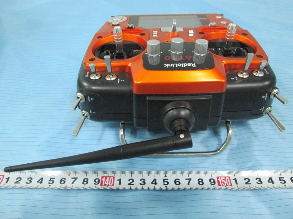
U2BRL039AT10
Sep 12, 2014Remote control
Equipment Class
DTS - Digital Transmission System