U4P30235Wireless Cable Router
Hitron TECHNOLOGIES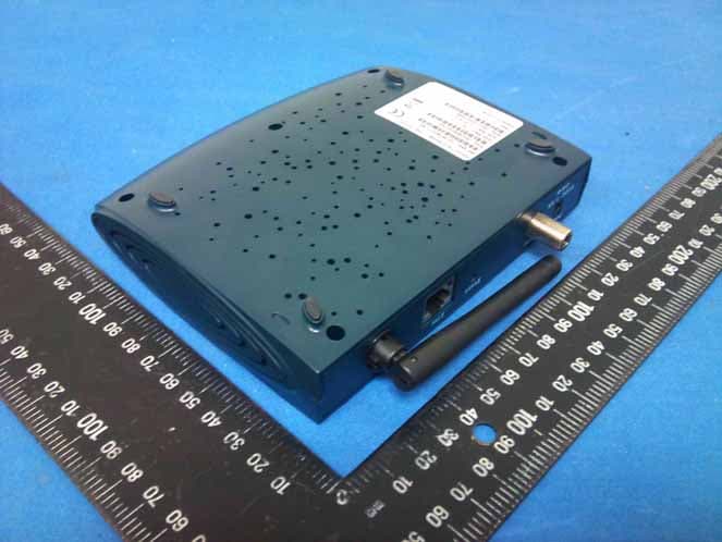
Click to zoom
Application Details
- Equipment Class
- DTS - Digital Transmission System
- Date of Grant
- Feb 13, 2012
- Application Purpose
- Original Equipment
- Date of Application
- Feb 09, 2012
- Equipment Note
- Wireless Cable Router
- Frequency Range
- 2422.00000000 - 2452.00000000
- Company
- Hitron TECHNOLOGIES
- Country
- Taiwan
Documents & Files
Document Text
Text extracted from the exhibit documents filed with the FCC. Open a document above to read the original.
Users Manual
Cable Modem Gateway Installation Poster Printed: May 2011 Package Contents The Broadband Residential Cable Modem Gateway ("cable modem") p ackage contains: 1 cable modem1 power adapter, (5VDC/1.5A )Caution: Be sure to use only the power adapter that came with t he cable modem. Using the wrong power adapter can damage the cable modem or cause uns table while operating.1 180 cm (6') CAT.5 UTP Ethernet cable.This Installation Poster. Before Installing the Cable Modem Local Cable Network ServiceBefore installing the cable modem,contact your local cable serv ice provider to check the availability of Internet/cable network access.Read the front and back panels of this Installation Poster thor oughly before attempting to install the cable modem. RF coaxial cable: One piece of coaxial cable if you are not using a cable lin e-splitter. Three pieces of coaxial cable if you are using a cable lin e-splitter. A cable line-splitter, if you wish to connect the cable modem a nd a television to the same wall cable outlet (optional). An active two-way cable line installed by your local cable oper ator. Computer System Requirements: Pentium processor equivalent (Pentium 166MHz or higher recommen ded). The original Windows 95, Windows 98, Windows ME, Windows 2000, or Windows XP CD- ROM or diskettes.TCP/IP protocol installed (see the "Configuring the TCP/IP Prot ocol on Your PC" section for more information about TCP/IP installation).An active Ethernet port or network interface card (NIC) install ed in your computer. The cable modem is OS-independent and can be connected to any c omputer equipped with an active standard RJ-45 10/100 Ethernet port.For USB connectivity: A computer running Windows 98, Windows ME, Windows 2000, or Windows XP operating system. An active USB port on your computer.For Ethernet connectivity: A PC running Windows 95, Windows 98, Windows ME, Windows NT , Windows 2000, or Windows XP operating system. Requirements Ethernet NIC Installation Process Configure the TCP/IP Protocol on Your PC A. Click Start, point to Settings , and then click Control Panel . B. Double-click the Network icon. The screen displays a list of installed network componen ts. C. Search for an entry containing TCP/IP, followed by the NIC hardware device installed in your computer. If you see TCP/IP listed next to your Eth ernet hardware device, you may now go to " Install the Cable Modem ." If TCP/IP is NOT listed, you must complete the following steps: 1. Click Add ... 2. Click Protocol , and then click Add ... 3. Click Microsoft in the " Manufacturers:" list and then click the " Network Protocols:" list. Click OK. You are prompted to restart you computer. D. Click Yes . You can now go to "Install the Cable Modem." 1 Windows 2000, Windows XP Operating System: A. Right-click My Network Places icon on the Windows desktop. B. Right-click Local Area Connection and click Properties . Search for an entry containing TCP/IP. If you see TCP/IP listed next to your Ethernet h ardware device, you can now go to " Install the Cable Modem." If TCP/IP is not listed, however, you must complete the following steps: 1. Scroll to the Internet Protocol (TCP/IP) option. 2. Click to mark the Internet Protocol check box with a check 3. Click OK . You can now go to " Install the Cable Modem." ˇ Install the Cable Modem Refer to the Ethernet NIC illustration, above, when making the following connections: A. Power off the computer and television.B. Unplug the computer and television. C. Connect the coaxial cable from the wall cable outlet to th e CATV connector on the back of the cable modem. Note: If you are using a cable line-splitter (not included) to connect the computer and a television to the same wall cable outlet, you will use three lengths of coaxial cable. As shown in the Ethernet NIC illustration, a cable line-spl itter has three connectors. Use the illustration to make the appropriate coaxial cable conne ctions. D. Connect one end of the Ethernet cable to the cable modem a nd the other end to the computer.E. Connect the 5VDC/1.5A power adapter to the back of the cab le modem. Caution: Be sure to use only the power adapter that came with t he cable modem. Using the wrong power adapter can damage the cable modem.F. Power on the modem by plugging the power adapter to a gro unded electrical outlet or surge protector plugged into a grounded electrical outle t. G. Plug in and turn on the computer and television.H. You can now go to "Check the LEDs." 2 Power Adapter (included) Wireless Cable Outlet Splitter (not included) To T V Notebook Wireless Installation Before installing the cable modem in the Ethernet mode, you mus t verify that your computer has the TCP/IP protocol installed. Follow the procedu re for your compute operating system to verify or install the TCP/IP protocol.Windows 95, Windows 98, or Windows ME Operating System: Check the LEDs After installation is complete, the cable modem is operating pr operly if the Power , Cable and Status LED lights are solid green. LED LABEL COLOR DESCRIPTION PowerCableStatusEthernetWireless GreenOrange-BlinkingOrangeGreen-BlinkingGreenGreenGreen-BlinkingGreenGreen-Blinking Cable modem is plugged in to an electrical outlet and is receiving powerThe modem is searching for the DOWNSTREAMfrequencyDownstream frequency is locked. Searching for UPSTREAM frequencyModem is registering with the cable company'shead-endModem is ready for data transfersValid Ethernet link statusCable modem is transmitting/receiving data through the Ethernet portWireless interface is connectedData is being sent/received through the Wireless port Note: Dark: Wireless is disabled Back Panel Interface ETHUSBCATVPowerReset RJ-45 female socket for connection of Ethernet cableUSB 'B'-type socket. Connects through USB cable to computer's USB 'A'-type port. (BRG-35302 only)RF connector to attach the cable for broadband Internet accessSocket to connect the power adapter included in the product pac kage Restores factory default sett…
Text truncated - open the document above for the full version.
Cover Letter(s)
FEDERAL COMMUNICATIONS COMMISSION DECLARATION OF CONFORMITY (DoC) Equipment:Wireless Cable Router Trademark(s) and Model(s):Hitron / CDW-30235XXXXXXXX (Where XXXXXXXX = any alpha character “a” - “z”, “A” - “Z”, or numeric character “0” - “9”, or combination of alpha and numeric characters.) Manufacturer:Hitron Technologies,Inc. FCC ID in case other parts of this equipment are subject to certification: U4P30235 This device complies with Part 15 of the FCC Rules. Operation is subject to the following two conditions: (1) this device may not cause harmful interference, and (2) this device must accept any interference received, including interference that may cause undesired operation. The following test reports are subject to this declaration: Test report number:Issue date: T110519301-D August 02, 2011 The following manufacturer/importer/entity (located in the USA) is responsible for this declaration: Company name: Hitron TECHNOLOGIES Name/Title (legal representative): Jimmy Li Address: No. 1-8, LISING 1ST RD., HSINCHU SCIENCE PARK,HSINCHU, Taiwan, 300 Phone: 886-3-578-6658 Fax: 886-3-579-4635 E-mail: [email protected] Date: 2012/02/03 Signature: FCC
External Photos
Report No.T110519301 Page 1 of 8 External Photo Report No.T110519301 Page 2 of 8 Report No.T110519301 Page 3 of 8 Power Adapter Photo Report No.T110519301 Page 4 of 8 Cable Photo
Internal Photos
Report No.T110519301 Page 5 of 8 Internal Photo Report No.T110519301 Page 6 of 8 Report No.T110519301 Page 7 of 8 Report No.T110519301 Page 8 of 8
RF Exposure Info
FCC IDU4P30235 Report No.T110519301-RP1 Page 115 / 120 This report shall not be reproduced, except in full, without the written approval of Compliance Certification Services Inc. APPENDIX I MAXIMUM PERMISSIBLE EXPOSURE According to FCC 1.1310 : The criteria listed in the following table shall be used to evaluate theenvironment impact of human exposure to radio frequency (RF) radiation as specified in 1.1307(b)LIMITS FOR MAXIMUM PERMISSIBLE EXPOSURE (MPE) Frequency Range (MHz) Electric Field Strength (V/m) Magnetic Field Strength (A/m) Power Density (mW/cm 2 ) Average Time (A) Limits for Occupational / Control Exposures 300-1,500 -- -- F/300 6 1,500-100,000 -- -- 5 6 (B) Limits for General Population / Uncontrol Exposures 300-1,500 -- -- F/1500 6 1,500-100,000 -- -- 1 30 CALCULATIONS Given d G×P×30 =E & 3770 E =S 2 Where E = Field strength in Volts / meter P = Power in Watts G = Numeric antenna gain d = Distance in meters S = Power density in milliwatts / square centimeter Combining equations and re-arranging the terms to express the distance as a function of the remaining variables yields: 2 d3770 G×P×30 =S Changing to units of mW and cm, using: P (mW) = P (W) / 1000 and d (cm) = d(m) / 100 Yields () () 22 d G×P ×0796.0= 100/d×3770 G×1000/P×30 =S Where d = Distance in cm P = Power in mW G = Numeric antenna gain S = Power density in mW / cm2 FCC IDU4P30235 Report No.T110519301-RP1 Page 116 / 120 This report shall not be reproduced, except in full, without the written approval of Compliance Certification Services Inc. LIMIT Power Density Limit, S=1.0mW/cm 2 TEST RESULTS Mode Antenna Gain (dBi) Minimum separation distance (cm) Output Power (dBm) Numeric antenna gain (mW) Power Density Limit (mW/cm 2 ) Power Density at 20cm (mW/cm 2 ) IEEE 802.11b 2.18 20.0 22.921.65 1.00 0.064375 IEEE 802.11g 2.18 20.0 21.071.65 1.00 0.042046 IEEE 802.11n HT202.18 20.0 20.901.65 1.00 0.040432 IEEE 802.11n HT402.18 20.0 21.931.65 1.00 0.051253 Remark: For mobile or fixed location transmitters, the maximum power density is 1.0 mW/cm 2 even if the calculation indicates that the power density would be larger.
Test Report
FCC IDU4P30235 Report No.T110519301-RP1 Page 1 / 120 This report shall not be reproduced, except in full, without the written approval of Compliance Certification Services Inc. FCC 47 CFR PART 15 SUBPART C AND ANSI C63.4:2003 TEST REPORT For Wireless Cable Router Model : CDW-30235XXXXXXXX (Where XXXXXXXX = any alpha character “a” - “z”, “A” - “Z”, or numeric character “0” - “9”, or combination of alpha and numeric characters.) Trade Name : Hitron Issued for Hitron Technologies,Inc. No. 1-8,Lihsin 1st Rd.,HsinChu Science Park, HishChu,Taiwan 300,R.O.C. Issued by Compliance Certification Services Inc. Hsinchu Lab. NO. 989-1 Wen Shan Rd., Shang Shan Village, Qionglin Shiang Hsinchu County 30741, Taiwan, R.O.C TEL: +886-3-5921698 FAX: +886-3-5921108 http://www.ccsrf.com E-Mail : [email protected] Issued Date: August 02, 2011 Note: This report shall not be reproduced except in full, without the written approval of Compliance Certification Services Inc. This document may be altered or revised by Compliance Certification Services Inc. personnel only, and shall be noted in the revision section of the document. The client should not use it to claim product endorsement by TAF or any government agencies. The test results of this report relate only to the tested sample identified in this report. FCC IDU4P30235 Report No.T110519301-RP1 Page 2 / 120 This report shall not be reproduced, except in full, without the written approval of Compliance Certification Services Inc. Revision History Rev. Issue Date Revisions Effect Page Revised By 00 08/02/2011 Initial Issue All Page 120 Winnie Chen FCC IDU4P30235 Report No.T110519301-RP1 Page 3 / 120 This report shall not be reproduced, except in full, without the written approval of Compliance Certification Services Inc. TABLE OF CONTENTS TITLE PAGE NO. 1. TEST REPORT CERTIFICATION ................................................................................ 4 2. EUT DESCRIPTION ..................................................................................................... 5 3. DESCRIPTION OF TEST MODES ............................................................................... 6 4. TEST METHODOLOGY ............................................................................................... 7 5. FACILITIES AND ACCREDITATION ........................................................................... 7 5.1 FACILITIES ............................................................................................................ 7 5.2 ACCREDITATIONS................................................................................................ 7 5.3 MEASUREMENT UNCERTAINTY ......................................................................... 8 6. SETUP OF EQUIPMENT UNDER TEST...................................................................... 9 7. FCC PART 15.247 REQUIREMENTS.......................................................................... 10 7.1 6dB BANDWIDTH .................................................................................................. 10-23 7.2 MAXIMUM PEAK OUTPUT POWER..................................................................... 24-38 7.3 AVERAGE POWER ............................................................................................... 39-41 7.4 POWER SPECTRAL DENSITY............................................................................. 42-56 7.5 CONDUCTED SPURIOUS EMISSION .................................................................. 57-75 7.6 RADIATED EMISSION........................................................................................... 76-109 7.7 CONDUCTED EMISSION ...................................................................................... 110-114 APPENDIX I MAXIMUM PERMISSIBLE EXPOSURE..................................................... 115-116 APPENDIX II SETUP PHOTOS .......................................................................................117-120 FCC IDU4P30235 Report No.T110519301-RP1 Page 4 / 120 This report shall not be reproduced, except in full, without the written approval of Compliance Certification Services Inc. 1. TEST REPORT CERTIFICATION Applicant Hitron Technologies,Inc. Address No. 1-8,Lihsin 1st Rd.,HsinChu Science Park, HishChu,Taiwan 300,R.O.C. Equipment Under Test Wireless Cable Router Model CDW-30235XXXXXXXX (Where XXXXXXXX = any alpha character “a” - “z”, “A” - “Z”, or numeric character “0” - “9”, or combination of alpha and numeric characters.) Trade Name Hitron Tested Date May19 ~ July 29, 2011 APPLICABLE STANDARD Standard Test Result FCC Part 15 Subpart C AND ANSI C63.4:2003 PASS WE HEREBY CERTIFY THAT: The above equipment has been tested by Compliance Certification Services Inc., and found compliance with the requirements set forth in the technical standards mentioned above. The results of testing in this report apply only to the product/system, which was tested. Other similar equipment will not necessarily produce the same results due to production tolerance and measurement uncertainties. Approved by: Reviewed by: Sb Lu Gundam Lin Sr. Engineer Sr. Engineer FCC IDU4P30235 Report No.T110519301-RP1 Page 5 / 120 This report shall not be reproduced, except in full, without the written approval of Compliance Certification Services Inc. 2. EUT DESCRIPTION Product Name Wireless Cable Router Model Number CDW-30235XXXXXXXX (Where XXXXXXXX = any alpha character “a” - “z”, “A” - “Z”, or numeric character “0” - “9”, or combination of alpha and numeric characters.) Identify Number T110519301 Received Date May 19, 2011 IEEE 802.11b/g, 802.11n HT20 : 2412MHz~2462MHz Frequency Range IEEE 802.11n HT40 : 2422MHz~2452MHz IEEE 802.11b : 22.92 dBm (0.1959W) IEEE 802.11g : 21.07 dBm (0.1279W) IEEE 802.11n HT20 : 20.90 dBm (0.1232W) Transmit Power IEEE 802.11n HT40 : 21.93 dBm (0.1560W) Channel Spacing IEEE 802.11b/g, 802.11n HT20/HT40 : 5MHz IEEE 802.11b/g, 802.11n HT20 : 11 Channels Channel Number IEEE 802.11n HT40 : 7 Channels IEEE 802.…
Text truncated - open the document above for the full version.
Test Setup Photos
FCC IDU4P30235 Report No.T110519301-RP1 Page 117 / 120 This report shall not be reproduced, except in full, without the written approval of Compliance Certification Services Inc. APPENDIX II SETUP PHOTOS RADIATED EMISSION SETUP Below 1 GHz FCC IDU4P30235 Report No.T110519301-RP1 Page 118 / 120 This report shall not be reproduced, except in full, without the written approval of Compliance Certification Services Inc. Above 1 GHz FCC IDU4P30235 Report No.T110519301-RP1 Page 119 / 120 This report shall not be reproduced, except in full, without the written approval of Compliance Certification Services Inc. ANTENNA PORT CONDUCTED RF MEASUREMENT SETUP FCC IDU4P30235 Report No.T110519301-RP1 Page 120 / 120 This report shall not be reproduced, except in full, without the written approval of Compliance Certification Services Inc. CONDUCTED EMISSION SETUP
Contact Information
Applicant
Jimmy Li(Senior Engineer)
Technical Contact
Non-Technical Contact
Compliance Certification Services Inc.Kelly Tsai Kelly Tsai
Test Firm
Compliance Certification Services Inc.Winnie Chen
Technical Specifications
| # | Rule Parts | Frequency Range | Power Output |
|---|---|---|---|
| 2 | 15C | 2.42 GHz - 2.45 GHz | 160.00 mW |
Other Applications from Hitron TECHNOLOGIES

U4P-CGNVM
Sep 08, 2015Wireless Cable Gateway
Equipment Class
NII - Unlicensed National Information Infrastructure TX
U4P-HTEMN2
Jul 08, 2015MoCA to WiFi extender
Equipment Class
NII - Unlicensed National Information Infrastructure TX
U4P-HTGDS1
Mar 22, 2015Garage Door Sensor
Equipment Class
DTS - Digital Transmission System
U4P-CGNM
Jun 07, 2014D3 WiFi MoCA Gateway
Equipment Class
NII - Unlicensed National Information Infrastructure TX
U4P-CGNV2
Mar 31, 2014eMTA
Equipment Class
DTS - Digital Transmission System