U5MSRP350IIOBETHERMAL RECEIPT PRINTER
BIXOLON Co.,Ltd.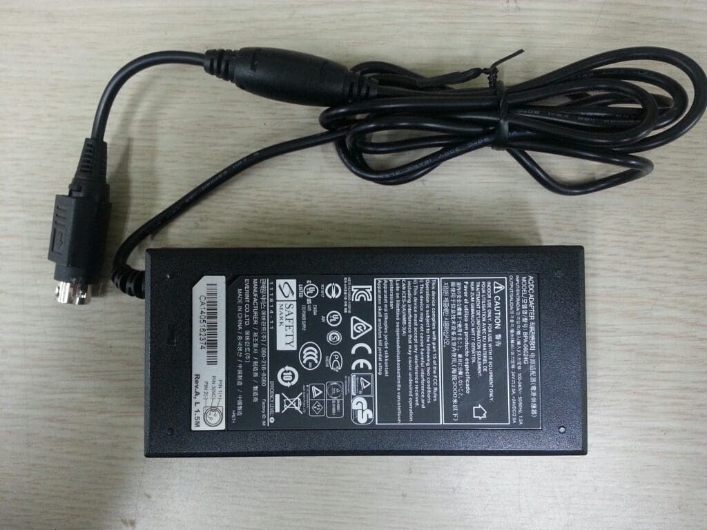
Click to zoom
Application Details
- Equipment Class
- DSS - Part 15 Spread Spectrum Transmitter
- Date of Grant
- Feb 08, 2015
- Application Purpose
- Original Equipment
- Date of Application
- Feb 08, 2015
- Equipment Note
- THERMAL RECEIPT PRINTER
- Frequency Range
- 2402.00000000 - 2480.00000000
- Company
- BIXOLON Co.,Ltd.
- Country
- South Korea
Documents & Files
Document Text
Text extracted from the exhibit documents filed with the FCC. Open a document above to read the original.
Users Manual
User's Manual SRP-350IIOBE Thermal Printer Rev. 1.00 http://www.bixolon.com Rev. 1.00 - 2 - SRP-350IIOBE ■ Safety Precautions In using the present appliance, please keep the following safety regulations in order to prevent any hazard or material damage. WARNING Violating following instructions can cause serious injury or death. Do not bend the cable by force or leave it under any heavy object. • A damaged cable can cause a fire. Do not plug in or unplug with your hands wet. • You can be electrocuted. Keep the plastic bag out of children’s reach. • If not, a child may put the bag on his head. Do not pull the cable to unplug. • This can damage the cable, which is the origin of a fire or a breakdown of the printer. You must use only the supplied adapter. • It is dangerous to use other adapters. Do not plug several products in one multi-outlet. • This can provoke over-heating and a fire. • If the plug is wet or dirty, dry or wipe it before usage. • If the plug does not fit perfectly with the outlet, do not plug in. • Be sure to use only standardized multi-outlets. PROHIBITED PROHIBITED PROHIBITED PROHIBITED PROHIBITED ONLY SUPPLIED ADAPTER PROHIBITED Rev. 1.00 - 3 - SRP-350IIOBE CAUTION Violating following instructions can cause slight wound or damage the appliance. Do not use the printer when it is out of order. This can cause a fire or an electrocution. • Switch off and unplug the printer before calling your dealer. Do not let water or other foreign objects in the printer. • If this happened, switch off and unplug the printer before calling your dealer. Use only approved accessories and do not try to disassemble, repair or remodel it for yourself. • Call your dealer when you need these services. • Do not touch the blade of auto cutter. Install the printer on the stable surface. • If the printer falls down, it can be broken and you can hurt yourself. Keep the desiccant out of children’s reach. • If not, they may eat it. If you observe a strange smoke, odor or noise from the printer, unplug it before taking following measures. • Switch off the printer and unplug the set from the mains. • After the disappearance of the smoke, call your dealer to repair it. TO UNPLUG PROHIBITED DISASSEMBLING PROHIBITED PROHIBITED PROHIBITED TO UNPLUG PRINTER PRINTER PRINTER PRINTER DEALER PRINTER Rev. 1.00 - 4 - SRP-350IIOBE ■ Warning - U.S.A 1) NOTE: This equipment has been tested and found to comply with the limits for a Class B digital device, pursuant to Part 15 of the FCC Rules. These limits are designed to provide reasonable protection against harmful interference in a residential installation. This equipment generates, uses and can radiate radio frequency energy and, if not installed and used in accordance with the instructions, may cause harmful interference to radio communications. However, there is no guarantee that interference will not occur in a particular installation. If this equipment does cause harmful interference to radio or television reception, which can be determined by turning the equipment off and on, the user is encouraged to try to correct the interference by one or more of the following measures: -- Reorient or relocate the receiving antenna. -- Increase the separation between the equipment and receiver. -- Connect the equipment into an outlet on a circuit different from that to which the receiver is connected. -- Consult the dealer or an experienced radio/TV technician for help. 2) Changes or modifications not expressly approved by the manufacturer could void the user's authority to operate the equipment. This device complies with Part 15 of the FCC Rules. Operation is subject to the following two conditions: (1) this device may not cause harmful interference, and (2) this device must accept any interference received, including interference that may cause undesired operation. ■ Notice - Canada This Apparatus complies with class “B” limits for radio interference as specified in the Canadian department of communications radio interference regulations. Get appareil est conforme aux normes class “B” d’interference radio tel que specifier par ministre canadien des communications dans les reglements d’interference radio. ■ Caution Some semiconductor devices are easily damaged by static electricity. You should turn the printer “OFF”, before you connect or remove the cables on the rear side, in order to guard the printer against the static electricity. If the printer is damaged by the static electricity, you should turn the printer “OFF”. Rev. 1.00 - 5 - SRP-350IIOBE ■ Waste Electrical and Electric Equipment (WEEE) This marking shown on the product or its literature, indicates that is should not be disposed with other household wastes at the end of its working life, To prevent possible harm to the environment or human health from uncontrolled waste disposal, please separate this from other types of wastes and recycle it responsibly to promote the sustainable reuse of material resources. Household users should contact either the retailer where they purchased this product, or their local government office, for details of where and how they can take this item for environmentally safe recycling. Business users should contact their supplier and check the terms and conditions of the purchase contract. This product should not be mixed with other commercial wastes for disposal. ■ Label Material * Control Label: PC * Other Labels: PET Rev. 1.00 - 6 - SRP-350IIOBE ■ Introduction The SRP-350IIOBE Roll Printer are designed for use with electronic instruments such as system ECR, POS, banking equipment, computer peripheral equipment, etc. The main features of the printer are as follows: 1. High speed printing : 47.28 (1/6” Feed) lines per second. 2. Low noise thermal printing. 3. USB / Ethernet / Bluetooth On-board Type 4. The data buffer allows the unit to receive print data even during printing. 5. Peripheral units drive circuit enables control of external devices such as cash drawer. 6. Characters can…
Text truncated - open the document above for the full version.
Attestation Statements
7th-8th FL, MiraeAsset Venture Tower, 20, Pangyoyeok-ro 241beon-gil, Bundang-gu, Seongnam-si, Gyeonggi-do, Korea Tel No : +82-31-218-5582 Fax No : +82-31-218-5589 ATTESTATION STATEMENT In re : BIXOLON Co., Ltd. FCC ID : U5MSRP350IIOBE Date : February 04, 2015 15.247(a)(1) The hopping sequence is random. Each hopping channels is used equally on the average. The receiver input bandwidth matches the bandwidth of the transmitted signal. The receiver has the ability to shift frequencies in synchronization with the transmitted signals. Example of a 79 hopping sequence in data mode: 20 62 46 77 7 64 8 73 16 75 1 15.247(g) The system is designed to comply with all of the regulations in Section 15.247 when the transmitter is presented with a continuous data (or information). 15.247(h) The system does not coordinate its channel selection/hopping sequence with other frequency hopping systems for the express purpose of avoiding the simultaneous occupancy of individual hopping frequencies by multiple transmitters. Sincerely, Young-taek Lee / Assistant Manager
Cover Letter(s)
Rev 11/20/07 7th-8th FL, MiraeAsset Venture Tower, 20, Pangyoyeok-ro 241beon-gil, Bundang-gu, Seongnam-si, Gyeonggi-do, Korea Tel No : +82-31-218-5582 Fax No : +82-31-218-5589 Federal Communications Commission Authorization and Evaluation Division Confidentiality Request regarding application for certification of FCC ID: U5MSRP350IIOBE Pursuant to Sections 0.457 and 0.459 of the Commission’s Rules, we hereby request confidential treatment of information accompanying this application as outlined below: Exhibit Type File Name Block Diagram Schematics Parts List Operational description Block Diagram (U5MSRP350IIOBE).pdf Schematics (U5MSRP350IIOBE).pdf Part List (U5MSRP350IIOBE).pdf Operational Description (U5MSRP350IIOBE).pdf The above materials contain trade secrets and proprietary information not customarily released to the public. The public disclosure of these materials may be harmful to the applicant and provide unjustified benefits to its competitors. The applicant understands that pursuant to Section 0.457 of the Rules, disclosure of this application and all accompanying documentation will not be made before the date of the Grant for this application. Pursuant to DA04-1705 June 15, 2004 of the Commission’s public notice, we also request temporary confidential treatment of information accompanying this application as outlined below: Exhibit Type File Name - - Sincerely, Jinseob Oh / CEO BIXOLON Co., Ltd.
External Photos
CTK Co., Ltd. (Ho-dong), 113, Yejik-ro, Cheoin-gu, Yongin-si, Gyeonggi-do, Korea Tel: +82-31-339-9970 Fax: +82-31-624-9501 www.e-ctk.com EUT External Photographs CTK Co., Ltd. (Ho-dong), 113, Yejik-ro, Cheoin-gu, Yongin-si, Gyeonggi-do, Korea Tel: +82-31-339-9970 Fax: +82-31-624-9501 www.e-ctk.com CTK Co., Ltd. (Ho-dong), 113, Yejik-ro, Cheoin-gu, Yongin-si, Gyeonggi-do, Korea Tel: +82-31-339-9970 Fax: +82-31-624-9501 www.e-ctk.com CTK Co., Ltd. (Ho-dong), 113, Yejik-ro, Cheoin-gu, Yongin-si, Gyeonggi-do, Korea Tel: +82-31-339-9970 Fax: +82-31-624-9501 www.e-ctk.com EUT dimension CTK Co., Ltd. (Ho-dong), 113, Yejik-ro, Cheoin-gu, Yongin-si, Gyeonggi-do, Korea Tel: +82-31-339-9970 Fax: +82-31-624-9501 www.e-ctk.com CTK Co., Ltd. (Ho-dong), 113, Yejik-ro, Cheoin-gu, Yongin-si, Gyeonggi-do, Korea Tel: +82-31-339-9970 Fax: +82-31-624-9501 www.e-ctk.com Adapter
ID Label/Location Info
CTK Co., Ltd. (Ho-dong), 113, Yejik-ro, Cheoin-gu, Yongin-si, Gyeonggi-do, Korea Tel: +82-31-339-9970 Fax: +82-31-624-9501 www.e-ctk.com Label and Location
Internal Photos
CTK Co., Ltd. (Ho-dong), 113, Yejik-ro, Cheoin-gu, Yongin-si, Gyeonggi-do, Korea Tel: +82-31-339-9970 Fax: +82-31-624-9501 www.e-ctk.com EUT Internal Photographs CTK Co., Ltd. (Ho-dong), 113, Yejik-ro, Cheoin-gu, Yongin-si, Gyeonggi-do, Korea Tel: +82-31-339-9970 Fax: +82-31-624-9501 www.e-ctk.com Main Board CTK Co., Ltd. (Ho-dong), 113, Yejik-ro, Cheoin-gu, Yongin-si, Gyeonggi-do, Korea Tel: +82-31-339-9970 Fax: +82-31-624-9501 www.e-ctk.com Sub Board CTK Co., Ltd. (Ho-dong), 113, Yejik-ro, Cheoin-gu, Yongin-si, Gyeonggi-do, Korea Tel: +82-31-339-9970 Fax: +82-31-624-9501 www.e-ctk.com BT Board Antenna
Operational Description
3/21 page - Contents - •표지............................................................1p •목차............................................................3p 1. Revision History ......................................... 4p 2. Features & Applications ..............................5p 3. Electrical Specifications ..............................6p 4. Measurements Method & Conditions ............. 11p 5. PCB Layout & Solder Pad size .....................12p 6. Antenna Dimensions .................................. 15p 7. Marking View .............................................15p 8. Reflow Profile ............................................ 16p 9. Environmental Tests ................................... 17p 10. Packaging ............................................... 18p 11. Usage and Cautions .................................18p 12. RoHS Data .............................................. 19p Ver 1.0 (2013.01.02) CONFIDENTIAL 4/21 page 1. Revision History product NKC -POS_A ModelSRP -350IIOBE Rev. No.Rev. IssuePageDesignedDate 1.0Appro. Issue-KC. NAM2013.01.02 Ver 1.0 (2013.01.02) CONFIDENTIAL 5/21 page 2. Features & Applications 2.1 Features This ceramic chip antenna is applied to 2.4 GHz ISM band applications, i.e. Bluetooth. Zigbee, Wireless LAN, etc... 형태 Bulk Ceramic 재질 유전체Al2O3(Alumina) 전극은(Ag) 크기 (mm) L = 10+/- 0.1 W = 2+/- 0.1 T = 1.2+/- 0.1 Weight 97~100 mg Ver 1.0 (2013.01.02) L T W CONFIDENTIAL 6/21 page 3. Electrical Specifications 3-1. * All item are measured in room temperature (24~25 ‘C). * All item are measured at customer set condition. No.ItemsTypical Data 1Frequency (MHz)2400 ~2500 2VSWR1.5 : 1 3Total Gain (Peak) [dBi ]0 4Impedance50 ohm 5PolarizationLinear Ver 1.0 (2013.01.02) CONFIDENTIAL 7/21 page 3-2. VSWR (S11)of USER SET condition Ver 1.0 (2013.01.02) CONFIDENTIAL 8/21 page 3-3. Radiation Patterns ThetaVertical Fieldof measured plane PhiHorizontal Fieldof measured plane 이득[dBi ] (Co -Pola ) Peak-3.02 Avg-8.34 Peak-0.94 Avg-5.32 Phi Theta Azimuth Elevation Ver 1.0 (2013.01.02) CONFIDENTIAL 9/21 page (Azimuth) Ver 1.0 (2013.01.02) CONFIDENTIAL 10/21 page (Elevation) Ver 1.0 (2013.01.02) CONFIDENTIAL 11/21 page 4. Measurements Method & Conditions The measurement of antenna performance is measurement of gain, radiation pattern using ORBIT/FR apparatus in Anechoic chamber and measurement of VSWR using Network analyzer. 4-1. The measurement of Frequency and VSWR [Measurement Method] 1. As seen the above, network analyzer is set up for S11measurement. 2. The measurement frequency range is to set up from 2 GHz to 3 GHz. 3. Perform S11 one port full calibration. 4. Measure the VSWR of three points of Bluetooth frequency range such as 2.4 GHz, 2.45 GHz, and 2.5 GHz. 4-2. The measurement of Gain & Radiation Patterns Ver 1.0 (2013.01.02) CONFIDENTIAL 12/21 page [Measurement Method] 1. As seen the above, network analyzer is to set up in Anechoic chamber. 2. As seen beneath, for the measurement planes as Azimuth, Elevation 1, and Elevation 2, measure Gain data of vertical polarization and horizontal polarization for each plane. 5. PCB Layout & Solder Pad size 5-1. Top Layout Unit : mm tolerances : +/- 0.05 Ver 1.0 (2013.01.02) Solder Pad 7 10 1.51.5 2 CONFIDENTIAL 5-2. Pad size & SOLDERING CREAM AREA 2.0 1.5 1.2 1.2 1.5 Solder Pad Soldering Cream Unit: mm 13/21 page Ver 1.0 (2013.01.02) Soldering Cream의 면적은 SMD 업체 현황(메탈 스크린 두께, 온도)에 따라 변경 될 수 있으므로협의를요함 1.5 7.3 CONFIDENTIAL 14/21 page 5-3. Antenna position Ver 1.0 (2013.01.02) CHIP ANT Solder Pad CONFIDENTIAL 15/21 page 6. Ag pattern & Dimensions 7. Marking View 7-1. 마킹 종류 * RF용 검정 잉크 사용 Ver 1.0 (2013.01.02) Only TOP part CONFIDENTIAL 16/21 page 8. Reflow Profile 8-1. Standard reflow condition(Pb-free) 8-2. 수동 납땜 (인두기)을 할 경우(Pb -free) 인두 온도 : 340 ‘C / 시간 : 각 단 max 3 sec Ver 1.0 (2013.01.02) Time(sec) 90~180 30~60 10~20 25 160 200 °C Peak temp 245 5 245 Temp( ) ∓ Preheat 130~180 SMD 업체 현황에따라 peak temp및 시간은변경 될 수 있으므로협의를요함 CONFIDENTIAL 17/21 page 9. Environmental Tests Ver 1.0 (2013.01.02) No.ITEMTEST CONDTEST REQU 1 High Temperature Resistance 1. Temp: +125±5°C 2. Time: 1000±24hrs 3. Measure Fc after left for 24hrs min. at room temp 1.Within electric spec(VSWR) 2. No visual damage 2 Low Temperature Resistance 1. Temp: -40 ±5°C 2. Time: 1000±24hrs 3. Measure Fc after left for 48hrs min. at room temp 1.Within electric spec(VSWR) 2. No visual damage 3 Thermal Shock 1. 1cycle/step1:-40 ±3°C,30min step2:+125±3°C,30min 2. Number of cycle:30 3. Measureafter left for 48hrs min. at room temp 1.Within electric spec(VSWR) 2. No visual damage 4Humidity 1. Humidity:85%RH 2. Temp:+85±3°C 3. Time:1000±24hrs 4. Measure Fc after left for 48hrs min. at room temp 1.Within electric spec(VSWR) 2. No visual damage 5 Adhesive strength of termination 1. Applied force on SMD chip till detached point from PCB.1. No mechanical damage by forces applied on the right 2. Strength(F)>5kgf F PCB chip CONFIDENTIAL
RF Exposure Info
CTK Co., Ltd. (Ho-dong), 113, Yejik-ro, Cheoin-gu, Yongin-si, Gyeonggi-do, Korea Tel: +82-31-339-9970 Fax: +82-31-624-9501 www.e-ctk.com Page 1 of 3 RF EXPOSURE EVALUATION Applicant : BIXOLON Co., Ltd. Applicant Address : 7th-8th FL, MiraeAsset Venture Tower, 20, Pangyoyeok-ro 241beon-gil, Bundang-gu, Seongnam-si, Gyeonggi-do, Korea Kind of Product : THERMAL RECEIPT PRINTER FCC ID : U5MSRP350IIOBE RF power : 9.3 dBm(8.51 mW) Peak Conducted Antenna type : Chip antenna Antenna Gain : 0.55 dBi Frequency Range : 2402 MHz - 2480 MHz Number of channels : 79 CH CTK Co., Ltd. (Ho-dong), 113, Yejik-ro, Cheoin-gu, Yongin-si, Gyeonggi-do, Korea Tel: +82-31-339-9970 Fax: +82-31-624-9501 www.e-ctk.com Page 2 of 3 ** RF Exposure Evaluation** Limits SAR Test Exclusion Thresholds for 100 MHz - 6 GHz and ≤ 50 mm Approximate SAR Test Exclusion Power Thresholds at Selected Frequencies and Test Separation Distances are illustrated in the following Table, The equation and threshold in Note 1 must be applied to determine SAR test exclusion. Note 1: The 1-g and 10-g SAR test exclusion thresholds for 100 MHz to 6 GHz at test separation distances ≤ 50 mm are determined by : CTK Co., Ltd. (Ho-dong), 113, Yejik-ro, Cheoin-gu, Yongin-si, Gyeonggi-do, Korea Tel: +82-31-339-9970 Fax: +82-31-624-9501 www.e-ctk.com Page 3 of 3 [(max. power of channel, including tune-up tolerance, mW)/(min. test separation distance, mm)]* [√f(GHz)] ≤ 3.0 for 1-g SAR and ≤ 7.5 for 10-g extremity SAR, whter - f(GHz) is the RF channel transmit frequency in GHz - Power and distance are rounded to the nearest mW and mm before calculation - The result is rounded to one decimal place for comparison - 3.0 and 7.5 are referred to as the numeric thresholds in the step 2 below The test exclusions are applicable only when the minimum test separation distance is ≤ 50 mm and for transmission frequencies between 100 MHz and 6 GHz. When the minimum test separation distance is < 5 mm, a distance of 5 mm according to 5) in section 4.1 is applied to determine SAR test exclusion. Output Power into Antenna : Frequency (MHz) Maximum output power to antenna (mW) SAR Test Exclusion Threshold (mW) 2441 8.51 10 Per FCC KDB 447498 D01v05r02, the SAR exclusion threshold for distances ≤50mm is defined by the following equation : [(max. power of channel, including tune-up tolerance, mW)/(min. test separation distance, mm)]* [√f(GHz)] ≤ 3.0 Base on the maximum conducted power of the antenna to use separation distance, SAR was not required; [(8.51 / 5) * √2.441] = 2.66 (≤ 3.0) Note: When the minimum test separation distance is < 5 mm, a distance of 5 mm is applied to determine SAR test exclusion.
Schematics
CAM350 V 9.5 : Tue Sep 10 14:43:43 2013 - (Untitled) : silk1.gbr CAM350 V 9.5 : Tue Sep 10 14:43:43 2013 - (Untitled) : silk2.gbr CAM350 V 9.5 : Tue Sep 03 13:18:18 2013 - (Untitled) : silk1.gbr CAM350 V 9.5 : Tue Sep 03 13:18:18 2013 - (Untitled) : silk2.gbr
Test Report
CTK Co., Ltd. (Ho-dong), 113, Yejik-ro, Cheoin-gu, Yongin-si, Gyeonggi-do, Korea Tel: +82-31-339-9970 Fax: +82-31-624-9501 www.e-ctk.com Test Report No.: CTK-2015-00133 Date: 2015-02-05 Page 1 of 55 This Report shall not be reproduced except in full without the written approval of CTK Form No.: CTK-RF-EF-Part15 SubpartC(Rev.2) TEST REPORT For FCC FCC Standards : FCC 47CFR part 15 subpart C Test Report No. : CTK-2015-00133 Date of Issue : 2015-02-05 FCC ID : U5MSRP350IIOBE Basic Model/Type No. : SRP-35*IIOBEz Kind of Product : THERMAL RECEIPT PRINTER Applicant : BIXOLON Co., Ltd. Applicant Address : 7th-8th FL, Miraeasset Venture Tower, 20, Pangyoyeok-ro 241beon-gil, Bundang-gu, Seongnam-si, Gyeonggi-do, Korea Manufacturer : BIXOLON Co., Ltd. Manufacturer Address : 7th-8th FL, Miraeasset Venture Tower, 20, Pangyoyeok-ro 241beon-gil, Bundang-gu, Seongnam-si, Gyeonggi-do, Korea Contact Person : Shin Ji Sung / Assistant Manager Telephone : +82–31-218-5582 Received Date : 2015-01-14 Test period : Start : 2014-11-20 End : 2014-11-24 Test Results : In Compliance Not in Compliance The test results presented in this report relate only to the object tested. Tested by Reviewed by Young-taek Lee Test Engineer Young-Joon, Park Technical Manager Date: 2015-02-05 Date: 2015-02-05 CTK Co., Ltd. (Ho-dong), 113, Yejik-ro, Cheoin-gu, Yongin-si, Gyeonggi-do, Korea Tel: +82-31-339-9970 Fax: +82-31-624-9501 www.e-ctk.com Test Report No.: CTK-2015-00133 Date: 2015-02-05 Page 2 of 55 This Report shall not be reproduced except in full without the written approval of CTK Form No.: CTK-RF-EF-Part15 SubpartC(Rev.2) REPORT REVISION HISTORY Date Revision Page No 2015-02-05 Issued (CTK-2015-00133) All This report shall not be reproduced except in full, without the written approval of CTK Co., Ltd. This document may be altered or revised by CTK Co., Ltd. personnel only, and shall be noted in the revision section of the document. Any alteration of this document not carried out by CTK Co., Ltd. will constitute fraud and shall nullify the document. CTK Co., Ltd. (Ho-dong), 113, Yejik-ro, Cheoin-gu, Yongin-si, Gyeonggi-do, Korea Tel: +82-31-339-9970 Fax: +82-31-624-9501 www.e-ctk.com Test Report No.: CTK-2015-00133 Date: 2015-02-05 Page 3 of 55 This Report shall not be reproduced except in full without the written approval of CTK Form No.: CTK-RF-EF-Part15 SubpartC(Rev.2) TABLE OF CONTENTS REPORT REVISION HISTORY ........................................................................................... 2 1.0 General Product Description ................................................................................ 4 1.1 Tested Frequency ............................................................................................... 4 1.2 Tested Mode ...................................................................................................... 4 1.3 Model Differences .............................................................................................. 5 1.4 Device Modifications ........................................................................................... 5 1.5 Peripheral Devices ............................................................................................. 5 1.6 Calibration Details of Equipment Used for Measurement ......................................... 5 1.7 Test Facility ....................................................................................................... 5 1.8 Laboratory Accreditations and Listings .................................................................. 6 2.0 Summary of tests .............................................................................................. 7 2.1 Transmitter Requirements ................................................................................... 8 2.1.1 Carrier Frequency Separation ........................................................................ 8 2.1.2 Number of Hopping Frequencies .................................................................. 10 2.1.4 Time of Occupancy (Dwell Time) .................................................................. 19 2.1.5 Maximum peak Conducted Output Power ...................................................... 25 2.1.6 RF Conducted Emissions ............................................................................. 30 2.1.7 Field Strength of Emissions ......................................................................... 41 2.1.8 AC Conducted Emissions ............................................................................. 50 APPENDIX A – Test Equipment Used For Tests ................................................................. 55 CTK Co., Ltd. (Ho-dong), 113, Yejik-ro, Cheoin-gu, Yongin-si, Gyeonggi-do, Korea Tel: +82-31-339-9970 Fax: +82-31-624-9501 www.e-ctk.com Test Report No.: CTK-2015-00133 Date: 2015-02-05 Page 4 of 55 This Report shall not be reproduced except in full without the written approval of CTK Form No.: CTK-RF-EF-Part15 SubpartC(Rev.2) 1.0 General Product Description Equipment model name SRP-35*IIOBEz Serial number Prototype EUT condition Pre-production, not damaged Antenna type Chip antenna Gain 0.55 dBi Frequency Range 2402 MHz - 2480 MHz RF power 8.00 dBm Peak Conducted (GFSK) 9.30 dBm Peak Conducted (8-DPSK) Type of Modulation Frequency Hopping Spread Spectrum Number of channels 79 Channel Spacing 1 MHz Channel Access Protocol Frequency Hopping Type of Modulation GFSK(1Mbps), DQPSK(2Mbps), 8-DPSK(3Mbps) Power Source AC/DC ADAPTER INPUT : 100-240V~, 1.5A OUTPUT : 24 VDC/2.5A 1.1 Tested Frequency LOW MID HIGH Frequency (MHz) 2402 2441 2480 1.2 Tested Mode - Pre-Scan has been conducted to determine the worst-case mode from all possible combinations between available modulations, data rates and antenna ports (if EUT with antenna diversity architecture). - Following channel(s) was (were) selected for the final test as listed below. Tested Ch Modulation Technology Modulation Type Packet Type Low, Mid, High FHSS GFSK DH5 Low, …
Text truncated - open the document above for the full version.
Contact Information
Applicant
JiSung Shin(Assistant Manager)
Test Firm
CTK Co., Ltd.Young-Joon Park
Technical Specifications
| # | Rule Parts | Frequency Range | Power Output |
|---|---|---|---|
| 1 | 15C | 2.40 GHz - 2.48 GHz | 8.50 mW |
Other Applications from BIXOLON Co.,Ltd.

U5MSPP-R310
Dec 23, 2015MOBILE PRINTER
Equipment Class
DSS - Part 15 Spread Spectrum Transmitter
U5MBGT-100P
Nov 24, 2015mPOS Thermal Printer
Equipment Class
DSS - Part 15 Spread Spectrum Transmitter
U5MIFJ-B
Mar 17, 2015BLUETOOTH INTERFACE
Equipment Class
DSS - Part 15 Spread Spectrum Transmitter
U5MSPPR200II
Dec 02, 2014MOBILE PRINTER
Equipment Class
DSS - Part 15 Spread Spectrum Transmitter
U5MNANO20BT
Apr 21, 2014Mobile Printer
Equipment Class
DSS - Part 15 Spread Spectrum Transmitter