U5XRE312Wireless Smoke Detector
Resolution Products, Inc.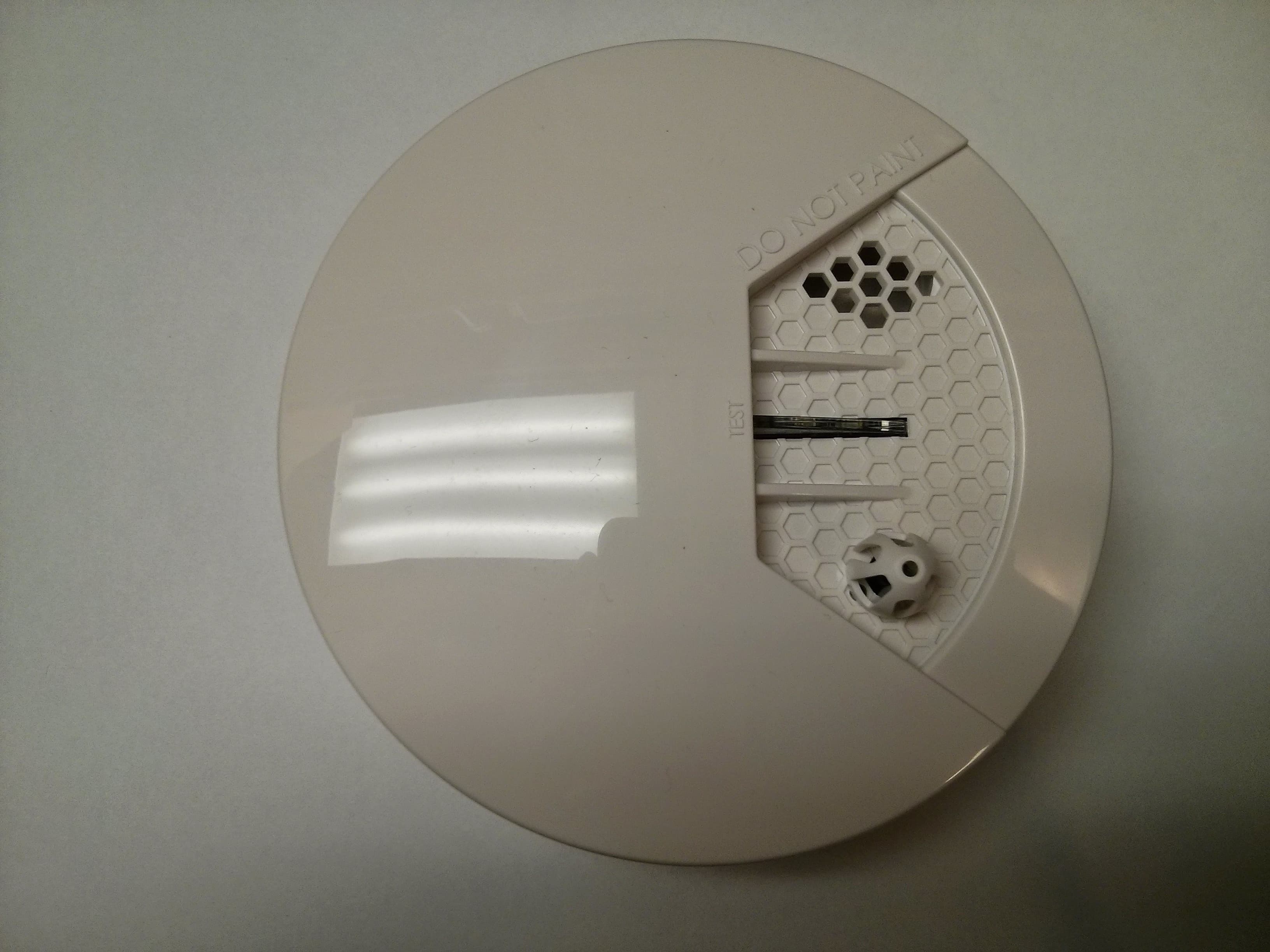
Click to zoom
Application Details
- Equipment Class
- DSC - Part 15 Security/Remote Control Transmitter
- Date of Grant
- Dec 22, 2014
- Application Purpose
- Original Equipment
- Date of Application
- Dec 22, 2014
- Equipment Note
- Wireless Smoke Detector
- Frequency Range
- 433.92000000 - 433.92000000
- Company
- Resolution Products, Inc.
- Country
- United States
Documents & Files
Document Text
Text extracted from the exhibit documents filed with the FCC. Open a document above to read the original.
Users Manual
Hourly CheckSupervisories, every hour Maintenance Needed Temporal 3 (Loud) Yellow (Pulsing) Supervisories Not Sent Replace Unit Specifications Approval:UL217 Self-Contained Fire Alarm Device Smoke Sensitivity: 1.31 – 2.28 %/ft (UL 217) 0.11 – 0.165 dB/m (EN54-7) Smoke Sensing Technology: Photoelectric Heat Alarm Point:135 – 149 F (UL 521) Alarm Sound:Temporal Three Replacement Battery: Panasonic CR123A Temperature Range: 32 to 120 F (Long Term) Humidity:10 – 85% Relative Humidity Housing dimensions: 4.7 inch diameter, 2.1 inch high Design & Manufacture: Resolution Products, Inc. Specifications subject to change without notice. Pictures RE312_DSC-Compat_Smoke_Instructions.docPage 2 of 322-Dec-14 24-Hour Tech Support Line: (715)808-0164 www.ResolutionProducts.com TEST Button LED Battery + Smoke Sensing Element Mounting Tabs Tamper Notices Verify proper enrollment and operation, per control panel installation instructions, at installation. PHOTOELECTRIC SMOKE & HEAT USER'S MANUAL, which is included in device box, is an integral part of the operating information of the RE312 device. However, this is NOT a heat device. Approved as a self-contained fire alarm device per UL217. This represents the ability of each individual sensor to sound locally upon sensed fire conditions. “GE”, “Interlogix”, “Honeywell”, “2GIG”, “DSC”, “Napco” are trademarks owned by General Electric Company, UTC Fire & Security Americas Corporation, Inc., Honeywell International Inc., 2GIG Technologies Inc., Tyco Safety Products Canada LTD, Napco Security Systems respectively. Resolution Products, Inc. products will function with one of either GE/Interlogix, Honeywell and 2GIG, DSC or Napco. However, no Resolution product is produced by, endorsed by, nor is officially associated with any of these other manufacturers. Resolution recommends verifying proper enrollment and operation, per control panel installation instructions, at installation. Warranty Resolution Products, Inc. will replace products that are defective in their first five (5) years. FCC Notice This device complies with Part 15 of the FCC rules. Operation is subject to the following two conditions: This device may not cause harmful interference. This device must accept any interference that may be received, including interference that may cause undesired operation. Changes or modifications not expressly approved by the Resolution Products, Inc. could void the user's authority to operate this equipment. FCC ID: U5X-RE312 IC Notice This device complies with Industry Canada license-exempt RSS standard(s). Operation is subject to the following two conditions: (1)This device may not cause interference, and (2)This device must accept any interference, including interference that may cause undesired operation of the device. Le présent appareil est conforme aux CNR d'Industrie Canada applicables aux appareils radio exempts de licence. L'exploitation est autorisée aux deux conditions suivantes : (1)l'appareil ne doit pas produire de brouillage, et (2)l'utilisateur de l'appareil doit accepter tout brouillage radioélectrique subi, même si le brouillage est susceptible d'en compromettre le fonctionnement. IC: 8310A-RE312 RE312_DSC-Compat_Smoke_Instructions.docPage 3 of 322-Dec-14 24-Hour Tech Support Line: (715)808-0164 www.ResolutionProducts.com
Cover Letter(s)
December 11, 2014 RE: Confidentiality Request for U5X-RE312/8310A-RE312 To Whom It May Concern: Pursuant to FCC 47 CRF 0.457(d) and 0.459 and IC RSP-100, Section 10, the applicant requests that a part of the subject FCC application be held confidential. Type of Confidentiality RequestedExhibit Short Term PermanentBlock Diagrams Short TermExternal Photos Short Term Permanent* 1 Internal Photos Short Term PermanentOperation Description/Theory of Operation Short Term PermanentParts List & Placement/BOM Short Term PermanentTune-Up Procedure Short Term PermanentSchematics Short TermTest Setup Photos Short Term Permanent*User’s Manual *Note: ______(Insert Explanation as Necessary)______ Resolution Products, Inc. has spent substantial effort in developing this product and it is one of the first of its kind in industry. Having the subject information easily available to "competition" would negate the advantage they have achieved by developing this product. Not protecting the details of the design will result in financial hardship. Permanent Confidentiality: The applicant requests the exhibits listed above as permanently confidential be permanently withheld from public review due to materials that contain trade secrets and proprietary information not customarily released to the public. Short-Term Confidentiality: The applicant requests the exhibits selected above as short term confidential be withheld from public view for a period of ___(specify number of days not to exceed 180) 2 ___ days from the date of the Grant of Equipment Authorization and prior to marketing. This is to avoid premature release of sensitive information prior to marketing or release of the 1 - The asterisked items (*) require further justification before permanent confidentiality will be allowed. These also currently require review by the FCC under their Permit-But-Ask policy before the grant is issued and can delay completion of an application. Further justification should be added to the note above. One such example for a potted device would be: “The EUT is FULLY potted using a non-removable epoxy based material. Removal of potting material causes irreparable damage to internal circuitry. See photographs exhibits that outline the device before and after potting.” 2 - Please refer to http://atcb.com/publicdocs/Memo-Short-Term-Vs-Standard-Confidentiality.pdf for complete details. product to the public. Applicant is also aware that they are responsible to notify ACB in the event information regarding the product or the product is made available to the public. ACB will then release the documents listed above for public disclosure pursuant to FCC Public Notice DA 04-1705. NOTE for Industry Canada Applications: The applicant understands that until such time that IC distinguishes between Short Term and Permanent Confidentiality, either type of marked exhibit above will simply be marked Confidential when submitted to IC. Sincerely, By:__________________________ Paul Saldin, Vice President (Signature/Title 3 )(Print name) 3 - Must be signed by applicant contact given for applicant on the FCC site, or by the authorized agent if an appropriate authorized agent letter has been provided. Letters should be placed on appropriate letterhead.
Cover Letter(s)
December 11, 2014 RE: U5X-RE312 Request for Limited Modular Approval To Whom It May Concern: We hereby request Limited Modular Approval for U5X-RE312 as described under 47 CFR 15.212(b). This device is usable on only one host device. Installation of module into completed device is under full control and done before shipping to the customer. The following pages describe the compliance of this device with the requirements. Sincerely, Paul Saldin Vice President Resolution Products, Inc. Applicant/GranteeResolution Products, Inc FCC ID:U5X-RE312 Section 15.212 Modular Transmitters Request for Modular ApprovalRequest for Limited Modular Approval RequirementsEUT ConditionsComply (Y/N) Single Modular Approval Requirements 1The radio elements of the modular transmitter must have their own shielding. The physical crystal and tuning capacitors may be located external to the shielded radio elements. Not required for LMAY 2The modular transmitter must have buffered modulation/data inputs (if such inputs are provided) to ensure that the module will comply with Part 15 requirements under conditions of excessive data rates or over-modulation. N/A - These inputs are not providedY 3The modular transmitter must have its own power supply regulation. Not required for LMAY 4The modular transmitter must comply with the antenna and transmission system requirements of Sections 15.203, 15.204(b) and 15.204(c). The antenna must either be permanently attached or employ a “unique” antenna coupler (at all connections between the module and the antenna, including the cable). The “professional installation” provision of Section 15.203 is not applicable to modules but can apply to limited modular approvals under paragraph (b) of this section. The antenna is permanently attached to the board and is not removable. Y 5The modular transmitter must be tested in a stand-alone configuration, i.e., the module must not be inside another device during testing for compliance with Part 15 requirements. Unless the transmitter module will be battery powered, it must comply with the AC line conducted requirements found in Section 15.207. AC or DC power lines and data input/output lines connected to the module must not contain ferrites, unless they will be marketed with the module (see Section 15.27(a)). The length of these lines shall be the length typical of actual use or, if that length is unknown, at least 10 centimeters to insure that there is no coupling between the case of the module and supporting equipment. Any accessories, peripherals, Not required for LMA. As specified in 15.212(b), the manufacturer must only "demonstrate by alternative means in the application for equipment authorization that the modular transmitter meets all the applicable Part 15 requirements under the operating conditions in which the transmitter will be used." We have done this by testing the device in the host with which it will be used. This is the ONLY host that may be used with this device. Y or support equipment connected to the module during testing shall be unmodified and commercially available (see Section 15.31(i)). 6The modular transmitter must be equipped with either a permanently affixed label or must be capable of electronically displaying its FCC identification number. (A) If using a permanently affixed label, the modular transmitter must be labeled with its own FCC identification number, and, if the FCC identification number is not visible when the module is installed inside another device, then the outside of the device into which the module is installed must also display a label referring to the enclosed module. This exterior label can use wording such as the following: “Contains Transmitter Module FCC ID: XYZMODEL1” or “Contains FCC ID: XYZMODEL1.” Any similar wording that expresses the same meaning may be used. The Grantee may either provide such a label, an example of which must be included in the application for equipment authorization, or, must provide adequate instructions along with the module which explain this requirement. In the latter case, a copy of these instructions must be included in the application for equipment authorization. (B) If the modular transmitter uses an electronic display of the FCC identification number, the information must be readily accessible and visible on the modular transmitter or on the device in which it is installed. If the module is installed inside another device, then the outside of the device into which the module is installed must display a label referring to the enclosed module. This exterior label can use wording such as the following: “Contains FCC certified transmitter module(s).” Any similar wording that expresses the same meaning may be used. The user manual must include instructions on how to access the electronic display. A copy of these instructions must be included in the application for equipment authorization. FCC label shall be affixed to the device so that it is visible when the module is installed in the host. Please see Internal Photos and ID Label Photos which show this. Y 7The modular transmitter must comply with any specific rules or operating requirements that ordinarily apply to a complete transmitter and the manufacturer must provide adequate instructions along with the module to explain any such requirements. A copy of these instructions must be included in the application for equipment authorization. We have provided instructions in the user manual. Y 8The modular transmitter must comply N/A - this device is not meant to be usedY with any applicable RF exposure requirements in its final configuration. near the body A limited modular approval may be granted for single or split modular transmitters that do not comply with all of the above requirements, e.g., shielding, minimum signaling amplitude, buffered modulation/data inputs, or power supply regulation, if the manufacturer can demonstrate by alternative means in the application for equipment authorization that the m…
Text truncated - open the document above for the full version.
External Photos
Exhibit A RE312 External Photos
ID Label/Location Info
Exhibit B RE312 Model Labels RE312 ID Label Photos
Internal Photos
Exhibit C RE312 Internal Photos
Test Report
Engineering Solutions & Electromagnetic Compatibility Services 360 Herndon Pkwy | Suite 1400 | Herndon | Virginia 20170 Phone: 703.689.0368 | Fax: 703.689.2056 | www.rheintech.com FCC Part 15.231 Test Data EUT: 433 MHz Smoke Detector 56-0062-03 Rev B01 for Resolution Engineering, Inc. 226 Locust Street, Suite 4 Hudson, WI 54016 Contact: Josh Gathje Testing Conducted By Rhein Tech Laboratories, Inc. 360 Herndon Parkway, Suite 1400 Herndon, VA 20170 RTL Test Engineer: Jon Wilson RTL Project/Report Number: 2013173 August 27, 2013 This report may not be reproduced, except in full, without the full written approval of Rhein Tech Laboratories, Inc. and Resolution Engineering. Test results relate only to the item tested. These tests are accredited and meet the requirements of ISO/IEC 17025 as verified by ANSI-ASQ National Accreditation Board/ACLASS. Refer to certificate and scope of accreditation AT-1445. Rhein Tech Laboratories, Inc. Client: Resolution Engineering 360 Herndon Parkway, Suite 1400 EUT: 433.92 MHz Smoke Detector Herndon, VA 20170 Standards: FCC Parts 2, 15 http://www.rheintech.com Report #: 2013173 2 of 5 Testing Represented in Report The data and limits presented in this report are for radiated emissions per 15.231(b)(2) which references 15.35(b), and peak limiting for restricted bands per 15.209(e), which again references 15.35(b)(2), as procured by Resolution Engineering. No average data is presented in this report. Data is also presented for spurious, non-harmonic radiated emissions per 15.209. The Equipment Under Test (EUT) was the 433 MHz Smoke Detector 56-0062-03 Rev B01 (RTL Bar Code 21240). 15.231 Radiated Emissions Test Data – FCC Limits/ 3m Distance Emission Frequency (MHz) Test Detector Antenna Polarity (H/V) Analyzer Reading (dBuV) Site Correction Factor (dB/m) Emission Level (dBuV/m) Limit (dBuV/m) Margin (dB) Pass/ Fail 216.963 Qp V 40.7 -20.2 20.5 46.0 -25.5 Pass 325.446 Qp H 44.2 -13.3 30.9 46.0 -15.1 Pass 433.920* Peak V 65.6 29.6 95.2 100.8 -5.6 Pass 542.400 Qp V 48.2 -5.9 42.3 46.0 -3.7 Pass 867.840 Peak V 73.7 -6.3 67.4 80.8 -13.4 Pass 1301.763 Peak V 60.0 -0.5 59.5 74.0 -14.5 Pass 1735.688 Peak H 47.0 3.7 50.7 80.8 -30.1 Pass 2169.590 Peak V 52.9 -18.7 34.2 80.8 -46.6 Pass 2603.510 Peak V 55.1 -18.5 36.6 80.8 -44.2 Pass 3037.430 Peak H 50.3 -18.6 31.7 80.8 -49.1 Pass 3471.350 Peak H 54.6 -17.2 37.4 80.8 -43.4 Pass 3905.270 Peak H 42.9 -16.8 26.1 74.0 -47.9 Pass 4339.190 Peak H 30.8 -11.2 19.6 74.0 -54.4 Pass * fundamental Test Procedure Radiated fundamental and spurious emissions were tested at three meters. The EUT was tested in the three orthogonal planes with the receive antenna in both polarities. The emissions were maximized per ANSI C63.4:2003 8.3.1.2; that is, the measurement antenna height was varied between 1 and 4 m, and the EUT was rotated through 360° on a rotating turntable until the maximum emissions were found. Both horizontal and vertical measurement antenna polarizations were used. A resolution bandwidth of 100 kHz was used for frequencies less than 1000 MHz, and a resolution bandwidth of 1 MHz was used for frequencies greater than or equal to 1000 MHz. The video bandwidth was set to a value at least three times greater than the resolution bandwidth. EUT Disposition The EUT was adapted to continuously transmit for testing purposes. Rhein Tech Laboratories, Inc. Client: Resolution Engineering 360 Herndon Parkway, Suite 1400 EUT: 433.92 MHz Smoke Detector Herndon, VA 20170 Standards: FCC Parts 2, 15 http://www.rheintech.com Report #: 2013173 3 of 5 Radiated Emissions Test Equipment Part Manufacturer Model Serial Number RTL Bar Code Calibration Due Date Amplifier (20 MHz-2 GHz) Rhein Tech Laboratories, Inc. PR-1040 900905 900905 9/28/14 Bilog Periodic Antenna (25 MHz-2 GHz) Schaffner Chase CBL6112 2099 900791 2/2/14 EMI Receiver RF Section (9 kHz-6.5 GHz) Hewlett Packard 85462A 3325A00159 900913 9/20/13 RF Filter Section (100 kHz-6.5 GHz) Hewlett Packard 85460A 3330A00107 900914 9/20/13 Spectrum Analyzer Hewlett Packard 8596EM 3826A00144 901215 3/15/14 Amplifier (1 GHz–26.0 GHz) Rhein Tech Laboratories, Inc. PR-1042 N/A 901364 9/28/13 Horn Antenna (2.0-4.0 GHz) EMCO 3161-02 9804-1044 900772 4/20/15 Emissions Testing Software Rhein Tech Laboratories, Inc. Automated Emission Tester Rev. 14.0.2 N/A N/A Test Personnel: Jon Wilson August 20, 2013 Test Engineer Signature Date of Test FCC/IC Cross Reference FCC 15.231(b)(2) RSS-210 Issue 8 A1.1 FCC 15.35(b) RSS-Gen Issue 3 7.2.3 FCC 15.205 RSS-Gen Issue 3 7.2.2 FCC 15.209 RSS-Gen Issue 3 7.2.5 Rhein Tech Laboratories, Inc. Client: Resolution Engineering 360 Herndon Parkway, Suite 1400 EUT: 433.92 MHz Smoke Detector Herndon, VA 20170 Standards: FCC Parts 2, 15 http://www.rheintech.com Report #: 2013173 4 of 5 Test Configuration Photograph Radiated Emissions Rhein Tech Laboratories, Inc. Client: Resolution Engineering 360 Herndon Parkway, Suite 1400 EUT: 433.92 MHz Smoke Detector Herndon, VA 20170 Standards: FCC Parts 2, 15 http://www.rheintech.com Report #: 2013173 5 of 5 EUT Photograph
Test Report
Resolution Products, Inc. Wireless Smoke Detector FCC ID: U5X-RE312 Certification Test Report December 11, 2014 U5X-RE312 Resolution Products, Inc.12/11/14Page 1 of 8 Test Report 1402 Heggen St. Hudson, WI 54016 Contents 1. Introduction.................................................................................................................................................................3 2. Statement of Compliance............................................................................................................................................3 2.1. FCC Part 2 §2.907................................................................................................................................................3 2.2. FCC Part 2 §2.911................................................................................................................................................3 2.3. FCC Part 2 §2.913................................................................................................................................................3 2.4. FCC Part 2 §2.915................................................................................................................................................3 2.5. FCC Part 2 §2.925................................................................................................................................................3 2.6. FCC Part 2 §2.943, 2.945....................................................................................................................................3 2.7. FCC Part 2 §2.947................................................................................................................................................3 2.8. FCC Part 2 §2.948................................................................................................................................................4 2.9. FCC Part 2 §2.1033..............................................................................................................................................4 3. Discussion of Laboratory Measurements and Rules Compliance...............................................................................5 3.1. FCC Part 15 §15.231(a)(1)..................................................................................................................................5 3.2. FCC Part 15 §15.231(a)(3)..................................................................................................................................5 3.3. FCC Part 15 §15.231(a)(4)..................................................................................................................................5 3.4. FCC Part 15 §15.231(a)(5)..................................................................................................................................6 3.5. FCC Part 15 §15.231(b).......................................................................................................................................6 3.5.1. Raw Field Strength Limits............................................................................................................................6 3.5.2. Duty Cycle Correction Factor and Resulting Limits.....................................................................................6 3.5.3. Measured Radiated Field Strength Data.......................................................................................................7 3.6. FCC Part 15 §15.231(c).......................................................................................................................................7 U5X-RE312 Resolution Products, Inc.12/11/14Page 2 of 8 Test Report 1402 Heggen St. Hudson, WI 54016 1.Introduction The RE312 is a wireless transmitter daughter board that plugs into a battery powered smoke detector. The transmitter gives wireless functionality to a smoke detector and sends alarms to a home security system. A PIC16LF1823 microcontroller monitors the smoke detector and transmits alarm packets when smoke is detected. The daughter board measures 1.875” by 2.125” and weights less than an ounce. The transmitter circuit consists of a 13.56MHz crystal and a Micrel MICRF113YM6 PLL Chip. This chip multiplies the crystal frequency to 433.92MHz. It also includes a circuit that allows ASK modulation of the 433.92MHz signal. A printed antenna on the PCB radiates the RF signal. Certification is requested under FCC Rules, Part 15, Subpart C, Paragraph 15.231. 2.Statement of Compliance Specific sections of FCC Rules Part 2 that require information or listing are given below. 2.1.FCC Part 2 §2.907 This is an application for certification of original equipment 2.2.FCC Part 2 §2.911 a)This application has been filed electronically using form 731. b)All required information has been supplied in this application and its attachments. c)This application has been electronically signed by an officer of Resolution Products, Inc. d)The technical test data has been signed by the agency performing the testing. e)Signature supplied in appropriate block on form 731. f)Processing fee has been paid. g)Signatures have been supplied electronically. 2.3.FCC Part 2 §2.913 a)This application has been filed electronically. b)Appropriate fees have been filed electronically. c)Equipment samples shall be supplied as requested. 2.4.FCC Part 2 §2.915 We are requesting a grant of certification. This application shows compliance with the technical standards. 2.5.FCC Part 2 §2.925 A label shall be affixed to each piece of equipment, showing the FCC identifier. The label shall read “FCC ID: U5X- RE312”. See Exhibit B for a photograph showing the label and location on the device. 2.6.FCC Part 2 §2.943, 2.945 Sample production equipment shall be submitted to the FCC upon request. 2.7.FCC Part 2 §2.947 a)Measurement procedure follows ANSI C63.4: 2009. b)A description of utilized test equipment is contained in the report. 2.8.FCC Part 2 §2.948 Radiated …
Text truncated - open the document above for the full version.
Test Setup Photos
U5X-RE312 8310A-RE312 Test Setup Photos
Contact Information
Applicant
Josh Gathje(Vice President)
Technical Contact
Resolution Products, Inc.Paul Saldin
[email protected]6512692172
1402 Heggen Street · Hudson, Wisconsin · United States
Test Firm
Rhein Tech Laboratories, Inc.Richard McMurray
Technical Specifications
| # | Rule Parts | Frequency Range | Power Output |
|---|---|---|---|
| 1 | 15.231 | 433.92 MHz - 433.92 MHz | - |
Other Applications from Resolution Products, Inc.

U5X-HUBPLUS
Jun 25, 2024Wireless Alarm Panel
Equipment Class
DSR - Part 15 Remote Control/Security Device Transceiver
U5X-RE229
Apr 15, 2020Glass Break Sensor
Equipment Class
DSC - Part 15 Security/Remote Control Transmitter
U5X-RE629
Apr 14, 2020Glass Break Sensor
Equipment Class
DSC - Part 15 Security/Remote Control Transmitter
U5X-RE129
Apr 14, 2020Glass Break Sensor
Equipment Class
DSC - Part 15 Security/Remote Control Transmitter
U5X-RE616
Jan 08, 2015Wireless Siren
Equipment Class
DSC - Part 15 Security/Remote Control Transmitter