U9R-W2CBW003802.11 b/g + Bluetooth Module
Wi2Wi, Inc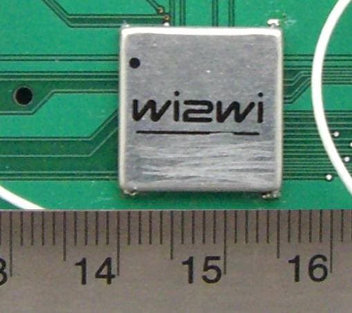
Click to zoom
Application Details
- Equipment Class
- DTS - Digital Transmission System
- Date of Grant
- Jun 01, 2007
- Application Purpose
- Original Equipment
- Date of Application
- Jun 01, 2007
- Equipment Note
- 802.11 b/g + Bluetooth Module
- Frequency Range
- 2412.00000000 - 2462.00000000
- Company
- Wi2Wi, Inc
- Country
- United States
Documents & Files
Document Text
Text extracted from the exhibit documents filed with the FCC. Open a document above to read the original.
Users Manual
Wi2Wi, Inc. Confidential 1 Wi2Wi, Inc. Confidential W2CBW003 (CSR BC04-ROM + Marvell 88W8686) Development Kit Quick Start Guide, Revision 1.3, Feb 5, 2007 1. Hardware and Software Requirements: • Notebook or Desktop with SDIO slot for WLAN and USB for Bluetooth. o Toshiba Satellite and IBM Thinkpad X40/X41, Dell Inspiron have been tested. • Windows XP with installation of service pack 2. • Bluetooth headset (if needed for audio streaming). • Wireless network for WLAN connectivity. 2. Card Interfaces and Connections SDIO Connector (WLAN) USB Connector WLAN Antenna Bluetooth Antenna Bluetooth Antenna Coaxial Connecto r WLAN Antenna Coaxial Connector UART Connector Figure #1: Card Interfaces and Connections Wi2Wi, Inc. Confidential 2 3. Directory Structure in the CD provided with the kit: • Bluetooth Driver & Toshiba Profile: Contains Bluetooth driver and Toshiba profiles • Hotfix921413: HB921413-v4.exe • SCMS Check Disable: Contains an executable to disable SMCS check for Toshiba stack • WLAN Driver: Contains WLAN driver files • W2CBW003_Quick_Start_Guide.pdf: Quick start guide for starting the kit 4. Software Setup: • Most notebooks with SD slot which only support 1-bit SD mode, HotfixKB 921413 will update SD slot into 4-bit mode which is work mode of W2CBW003 o run HB921413-v4.exe under directory Hotfix921413 http://support.microsoft.com/kb/921413 . • Plug in SDIO connector in the machine (see Figure #4) o Follow the pop-up windows (see Figure#2 and Figure #3) and complete the installation of WLAN driver present under “WLAN Driver” directory. Figure #2: WLAN Driver Installation Window #1 Wi2Wi, Inc. Confidential 3 • Unplug SDIO connector. • Run setup.exe under directory “Bluetooth Driver & Toshiba Profile” o It will take some time and ask you to restart notebook. 5. Executing WLAN and Bluetooth Applications: • Plug in SDIO connector. • Connect to a wireless network. • Connect USB connector for connecting to Bluetooth Headset. Click on Bluetooth icon on your right corner (you may have to “All Programs” under “Start” if you are not able to locate it). “Add New Connection Wizard” and “Bluetooth Settings” windows will pop up. Figure #3: WLAN Driver Installation Window #2 Wi2Wi, Inc. Confidential 4 • Choose “Custom Mode” in “Add New Connection Wizard” window (see Figure #4) and click “Next >”. Machine searches for all the available devices and shows them in “Bluetooth Settings” window (see Figure #5). • Connect to the desired Bluetooth device by clicking on the icon. It should turn green meaning that the connection is set. You may have to put your desired device in pairing mode to accomplish this. Figure #4: Bluetooth Connection Window #1 Wi2Wi, Inc. Confidential 5 • For video streaming, you can go to http://movies.yahoo.com/trailers and listen to the audio on a Bluetooth A2DP headset. • For VoIP applications, You can use it with Skype for making VoIP calls. 6. Important Notes: • Always plug in SDIO before plugging in USB due to SDIO bus limitations. • If you’re using MOTOROLA DC800 home stereo adapter or any other device where “SCMS check” is not enabled, you need to run “SwitchTosSCMSCheck.exe” under directory “SCMS Check Disable” to disable SCMS-T copy protection before connecting to the device. Figure #5: Bluetooth Connection Window #2
External Photos
Wi2Wi Inc. FCC ID: U9R-W2CBW003 Report #: R703307-247 802.11 Page 59 of 61 FCC Part 15.247 Test Report 15 EXHIBIT C – EUT EXTERNAL PHOTOGRAPHS 15.1 EUT Built in the Test Board 15.2 Test Board Solder Side View Wi2Wi Inc. FCC ID: U9R-W2CBW003 Report #: R703307-247 802.11 Page 60 of 61 FCC Part 15.247 Test Report 15.3 EUT Front View 15.4 Testing Antenna View
ID Label/Location Info
Wi2Wi Inc. FCC ID: U9R-W2CBW003 Report #: R703307-247 802.11 Page 54 of 61 FCC Part 15.247 Test Report 13 EXHIBIT A - FCC ID LABEL INFORMATION 13.1 FCC § 2.925 Identification of equipment (a) Each equipment covered in an application for equipment authorization shall bear a nameplate or label listing the following: (1) FCC Identifier consisting of the two elements in the exact order specified in §2.926. The FCC Identifier shall be preceded by the term FCC ID in capital letters on a single line, and shall be of a type size large enough to be legible without the aid of magnification. Example: FCC ID XXX123. XXX—Grantee Code 123—Equipment Product Code 13.2 FCC ID Labeling Requirements as per FCC § 15.19 (a) In addition to the requirements in part 2 of this chapter, a device subject to certification, or verification shall be labeled as follows: (3) All other devices shall bear the following statement in a conspicuous location on the device: This device complies with part 15 of the FCC Rules. Operation is subject to the following two conditions: (1) This device may not cause harmful interference, and (2) this device must accept any interference received, including interference that may cause undesired operation. (4) Where a device is constructed in two or more sections connected by wires and marketed together, the statement specified above is required to be affixed only to the main control unit. If the EUT is integrated within another device then a label affixed to the host shall also state, “Contains FCC ID:XXXXXX” (5) When the device is so small or for such use that it is not practicable to place the statement specified under paragraph (a) of this section on it, the information required by this paragraph shall be placed in a prominent location in the instruction manual or pamphlet supplied to the user or, alternatively, shall be placed on the container in which the device is marketed. However, the FCC identifier or the unique identifier, as appropriate, must be displayed on the device. 13.3 Suggested FCC ID Label Model: W2CBW003 This device complies with part 15 of the FCC Rules. Operation is subject to the following two conditions: (1) This device may not cause harmful interference, and (2) this device must accept any interference received, including interference that may cause undesired operation. FCC ID: U9R-W2CBW003 IC: 7089A-W2CBW003 Wi2Wi, Inc. Wi2Wi Inc. FCC ID: U9R-W2CBW003 Report #: R703307-247 802.11 Page 55 of 61 FCC Part 15.247 Test Report 13.4 Suggested Label Location
RF Exposure Info
Wi2Wi Inc. FCC ID: U9R-W2CBW003 Report #: R703307-247 802.11 Page 9 of 61 FCC Part 15.247 Test Report 4 § 15.247 (e) (i) and § 2.1091 - RF EXPOSURE 4.1 Applicable Standard According to §15.247(e)(i) and §1.1307(b)(1), systems operating under the provisions of this section shall be operated in a manner that ensures that the public is not exposed to radio frequency energy level in excess of the Commission’s guidelines. According to §1.1310 and §2.1091 RF exposure is calculated. Limits for General Population/Uncontrolled Exposure Limits for General Population/Uncontrolled Exposure Frequency Range (MHz) Electric Field Strength (V/m) Magnetic Field Strength (A/m) Power Density (mW/cm 2 ) Averaging Time (minutes) 0.3-1.34 614 1.63 *(100) 30 1.34-30 824/f 2.19/f *(180/f 2 ) 30 30-300 27.5 0.073 0.2 30 300-1500 / / f/1500 30 1500-100,000 / / 1.0 30 f = frequency in MHz * = Plane-wave equivalent power density 4.2 MPE Prediction Prediction of MPE limit at a given distance Equation from page 18 of OET Bulletin 65, Edition 97-01 S = PG/4πR² Where: S = power density P = power input to antenna G = power gain of the antenna in the direction of interest relative to an isotropic radiator R = distance to the center of radiation of the antenna 4.3 Test Result The power density level at 20 cm is 0.0133 mW/cm², which is below the uncontrolled exposure limit of 1.0mW/cm² at 2462 MHz. Maximum peak output power at antenna input terminal (dBm): 15.24 Maximum peak output power at antenna input terminal (mW): 33.42 Prediction distance (cm): 20 Prediction frequency (MHz): 2462 Maximum Antenna Gain, typical (dBi): 3 Maximum Antenna Gain (numeric): 1.995 Power density of prediction frequency at 20.0 cm (mW/cm 2 ): 0.0133 MPE limit for uncontrolled exposure at prediction frequency (mW/cm 2 ): 1.0
Test Report
Note: This test report is for the customer shown above and their specific product only. It may not be duplicated or used in part without prior written consent from Bay Area Compliance Laboratories Corp. This report must not be used by the customer to claim product certification, approval, or endorsement by NVLAP, NIST, or any agency of the Federal Government . FCC PART 15.247 MEASUREMENT AND TEST REPORT For Wi2Wi, Inc. 2107 N. First Street, Ste. 540 San Jose, CA 95131, USA FCC ID: U9R-W2CBW003 Model: W2CBW003 Report Type: Original Report Product Type: 802.11b/g +Bluetooth Module Test Engineer(s): James Ma Report Number: R0703307-247 802.11 Report Date: 2007-05-02 Reviewed By: RF Engineering Lead: Daniel Deng Prepared By: (ct) Bay Area Compliance Laboratories Corp. 1274 Anvilwood Ave. Sunnyvale, CA 94089, USA Tel: (408) 732-9162 Fax: (408) 732-9164 Wi2Wi Inc. FCC ID: U9R-W2CBW003 Report #: R703307-247 802.11 Page 2 of 52 FCC Part 15.247 Test Report TABLE OF CONTENTS 1 GENERAL INFORMATION .......................................................................................................................................4 1.1 PRODUCT DESCRIPTION FOR EQUIPMENT UNDER TEST (EUT) ............................................................................ 4 1.2 MECHANICAL DESCRIPTION OF EUT ................................................................................................................... 4 1.3 ANTENNA DESCRIPTION....................................................................................................................................... 4 1.4 EUT PHOTOGRAPH.............................................................................................................................................. 5 1.5 OBJECTIVE........................................................................................................................................................... 5 1.6 RELATED SUBMITTAL(S)/GRANT(S)..................................................................................................................... 5 1.7 TEST METHODOLOGY.......................................................................................................................................... 5 1.8 MEASUREMENT UNCERTAINTY............................................................................................................................ 6 1.9 TEST FACILITY..................................................................................................................................................... 6 2 SYSTEM TEST CONFIGURATION ..........................................................................................................................7 2.1 JUSTIFICATION..................................................................................................................................................... 7 2.2 EUT EXERCISE SOFTWARE.................................................................................................................................. 7 2.3 SPECIAL ACCESSORIES......................................................................................................................................... 7 2.4 EQUIPMENT MODIFICATIONS...............................................................................................................................7 2.5 LOCAL SUPPORT EQUIPMENT LIST AND DETAILS................................................................................................ 7 3 SUMMARY OF TEST RESULTS ...............................................................................................................................8 4 §15.203 - ANTENNA REQUIREMENT ......................................................................................................................9 4.1 APPLICABLE STANDARD...................................................................................................................................... 9 4.2 RESULT................................................................................................................................................................ 9 5 §15.207 - CONDUCTED EMISSIONS ........................................................................................................................10 5.1 SECTION 15.207 CONDUCTED LIMITS:................................................................................................................ 10 5.2 TEST SETUP....................................................................................................................................................... 10 5.3 TEST EQUIPMENT LIST AND DETAILS................................................................................................................. 10 5.4 TEST PROCEDURE.............................................................................................................................................. 10 5.5 TEST SETUP DIAGRAM....................................................................................................................................... 11 5.6 ENVIRONMENTAL CONDITIONS.......................................................................................................................... 11 5.7 SUMMARY OF TEST RESULTS............................................................................................................................. 11 6 §2.1051 & §15.247(d) - SPURIOUS EMISSIONS AT ANTENNA TERMINALS...................................................14 6.1 APPLICABLE STANDARD.................................................................................................................................... 14 6.2 MEASUREMENT PROCEDURE.............................................................................................................................. 14 6.3 EQUIPMENT LISTS.............................................................................................................................................. 14 6.…
Text truncated - open the document above for the full version.
Test Setup Photos
Wi2Wi Inc. FCC ID: U9R-W2CBW003 Report #: R703307-247 802.11 Page 56 of 61 FCC Part 15.247 Test Report 14 EXHIBIT B - TEST SETUP PHOTOGRAPHS 14.1 Conducted Emissions –Front View 14.2 Conducted Emissions – Side View Wi2Wi Inc. FCC ID: U9R-W2CBW003 Report #: R703307-247 802.11 Page 57 of 61 FCC Part 15.247 Test Report 14.3 Unintentional Radiated Emissions – Front View 14.4 Unintentional Radiated Emissions – Rear View Wi2Wi Inc. FCC ID: U9R-W2CBW003 Report #: R703307-247 802.11 Page 58 of 61 FCC Part 15.247 Test Report 14.5 Radiated Emissions – Front View 14.6 Radiated Emissions – Rear View
Contact Information
Applicant
Dhruv Shah(VP of Engineering)
Test Firm
Bay Area Compliance LaboratoryJohn Chan
Technical Specifications
| # | Rule Parts | Frequency Range | Power Output |
|---|---|---|---|
| 2 | 15C | 2.41 GHz - 2.46 GHz | 19.28 mW |
Other Applications from Wi2Wi, Inc
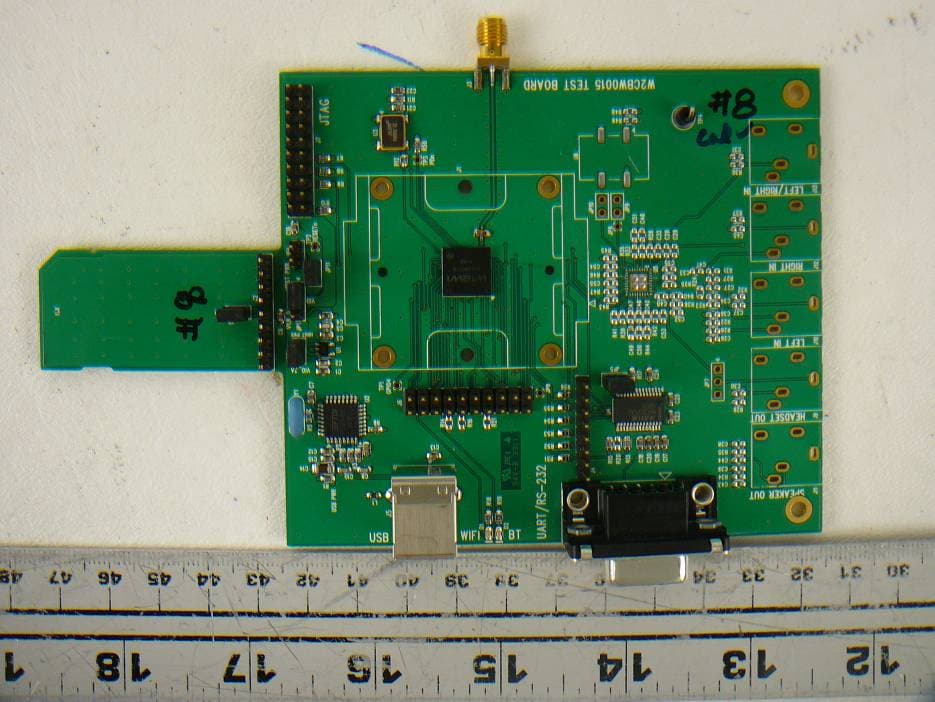
U9R-W2CBW0015
Oct 04, 2012WLAN+Bluetooth Module
Equipment Class
DSS - Part 15 Spread Spectrum Transmitter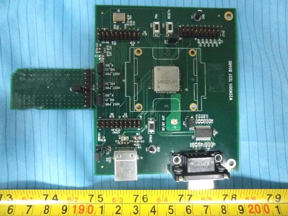
U9R-W2SW0011
Jul 24, 2012WiFi 802.11bgn Module
Equipment Class
DTS - Digital Transmission System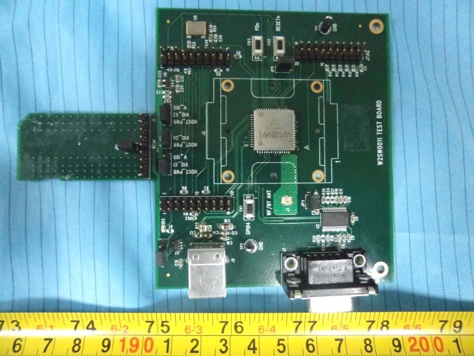
U9R-W2SW0011U
Dec 19, 2011Wireless 802.11b/g/n Module
Equipment Class
DTS - Digital Transmission System
U9R-W2CBW009DI
Aug 21, 2010WLAN-Bluetooth Module
Equipment Class
DSS - Part 15 Spread Spectrum Transmitter
U9R-W2CBW009S
Aug 21, 2010WLAN-Bluetooth Module
Equipment Class
DSS - Part 15 Spread Spectrum Transmitter