U9XKCODES-604KC604X printer server
KCodes Corporation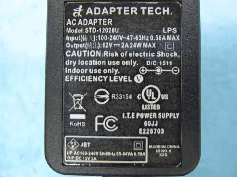
Click to zoom
Application Details
- Equipment Class
- DTS - Digital Transmission System
- Date of Grant
- Jun 28, 2015
- Application Purpose
- Original Equipment
- Date of Application
- Jun 28, 2015
- Equipment Note
- KC604X printer server
- Frequency Range
- 2412.00000000 - 2462.00000000
- Company
- KCodes Corporation
- Country
- Taiwan
Documents & Files
Document Text
Text extracted from the exhibit documents filed with the FCC. Open a document above to read the original.
Users Manual
© 2014 KCodes Corporation. All rights reserved. 6 Series v2 User’s Manual V1.0 KCodes 6 Series v2 USB 2.0 Device Server User’s Manual Chapter 1 Introduction Thank you for purchasing 601/601n/604/604n USB Device Server (in the following referred to as “Server”). This Server is designed to connect your Multifunction Printer, Scanner, Fax, Multifunction Printer, Hard Drive, iPhone, iPod, USB Digital TV Tuner, Digital Camera, USB Webcam, USB Speaker, USB CD, USB DVD to your network, allowing all network users’ access to these shared USB devices. 1.1 About 4 Models Described in this Manual This manual provides introductory information as well as detailed instructions on how to set up and manage 6 Series in various network environments. The following table shows the differences among the 4 models. All 4 models have a 10/100 Mbit/sec Lan port. However, 601 v2 and 601n v2 has only one USB port, while both 604 v2 and 604n v2 have four USB ports. Compared with 4 models have an additional wireless module (802.11b/g/n). Except for the wireless configuration, most configuration and operations are the same for 601 v2/604 v2 and 601n v2/604n v2. Similarly, almost all of the configuration and operations are the same for these models except that only one USB device can be connected to 601 v2/601n v2 while at most four USB devices can be connected to 604 v2/604n v2. Unless explicitly specified, all instructions in the manual apply to 6 Series. Model Name LAN Wireless USB Port(s) 601 v2 Yes No 1 604 v2 Yes No 4 601n v2 Yes Yes 1 604n v2 Yes Yes 4 To fully benefit from this document, you should be familiar with basic networking principles. The instructions described in this manual are based on the settings in a new Server. To reload the Factory Parameters, you can reset this Server back to Factory Default, which will restore most of the settings. For details, please refer to the chapter “Restore Factory Defaults”. 1.2 Customer Support Should you require any technical assistance, please contact your product reseller. Or you can visit our website for latest product information. This document is subject to changes without prior notice. © 2014 KCodes Corporation. All rights reserved. 6 Series v2 User’s Manual V1.0 Chapter 2 Product Overview 2.1 Package Contents Verify that nothing is missing from the package by using the checking list below. Please contact your dealer if anything is missing or damaged. All packing materials are recyclable. Please confirm the items in the package below: This Server ( 601/601n/604/604n) CD (Control Center and User’s Manual and Quick Installation Guide) Power Adaptor 2.2 Product CD This CD provides easy-to-use Control Center software, and the User’s Manual and Quick Installation Guide. 2.2.1. Start-up Procedures If your computer is configured to auto start CDs, this CD will start automatically when inserted. You can also navigate to the CD and start the autorun.exe file from within the Windows file manager. 2.3 Physical Description 1. Power Adaptor Connector : 5V/1A (for 601 v2/601n v2) or 12V/2A (for 604 v2/604n v2) 2. Init Button : for restoring the configurable parameters to the default values 3. Wireless Station (only for 601n v2/604n v2) : IEEE 802.11 b/g/n wireless station with antenna 4. Ethernet Connector : connected to a twisted pair category 5 cable 5. USB Host Ports: USB 1.1/2.0 low, full, and Hi-Speed compliant 6. Indicators For 6 Series Power Indicator is lit while power is applied. If it is not lit, or if it blinks, there is a problem with the USB device server or Power Adapter. USB Indicator (one for 601 v2/601n v2, four for 604 v2/604n v2) is lit while a USB device connects to a USB Port of the USB device server. If it is not lit, there is a problem with the USB device or the USB device server. For 601 v2/604 v2 Link Status is lit while network is applied. If it is not lit, it indicates that this server does not connect to the network. Status Indicator blinks to indicate network activity. © 2014 KCodes Corporation. All rights reserved. 6 Series v2 User’s Manual V1.0 For 601n v2/604n v2 LAN Indicator blinks to indicate wired network activity. If it is lit, it indicates the wired network is applied. If it is not lit, it indicates that the server does not connect to the wired network. WLAN Indicator blinks to indicate wireless network activity. If it is lit, it indicates the wireless network is applied. If it is not lit, it indicates that the server does not connect to the wireless network. 2.4 Supported USB Devices The USB device server supports the following types of USB devices. USB Printer USB multifunction printer (MFP/AIO) USB scanner USB storage iPad iPhone © 2014 KCodes Corporation. All rights reserved. 6 Series v2 User’s Manual V1.0 Chapter 3 Basic Installation 3.1. Connecting the Hardware 1. Make sure that your USB devices are switched off and that the Server’s Power Adapter is disconnected. 2. Connect the USB devices to the USB ports with the USB cables. 3. Connect the Server to the network with a twisted-pair category 5 cable, 10baseT or 100baseTX. 4. Turn on the USB devices and make sure it is ready for use. 5. Connect the Power Adapter to the Server. The power indicator will light up and USB1 and USB2 indicators will flash in turn. (For 601/601n, only USB1 indicator will flash.) When the Link indicator lights up, the Server is correctly connected to the network. When USB1 and USB2 indicators stop flashing, the Server starts to work normally. 3.2. Wireless connection This section only applies to 601n/604n. 3.3.1. Preliminary Before you can access wireless network, wireless parameters should be set correctly. You have to setup the first wireless parameter set through LAN (wired) connection. Wireless access can be set as infrastructure (station) mode, which need an access point to route network messages with the same SSID. Wireless access can be secured by WEP (64/128), WPA-PSA (TKIP/AES), and WPA2-PSK (AES). If p…
Text truncated - open the document above for the full version.
External Photos
Report No.:560301 SPORTON International Inc. PAGE NUMBER : 1 OF 4 TEL : 886-3-327-3456 ISSUED DATE : Jun. 25, 2015 FAX : 886-3-327-0973 Photographs of EUT Report No.:560301 SPORTON International Inc. PAGE NUMBER : 2 OF 4 TEL : 886-3-327-3456 ISSUED DATE : Jun. 25, 2015 FAX : 886-3-327-0973 Report No.:560301 SPORTON International Inc. PAGE NUMBER : 3 OF 4 TEL : 886-3-327-3456 ISSUED DATE : Jun. 25, 2015 FAX : 886-3-327-0973 Adapter Brand holder: Adapter Technology Co., Ltd. Model: STD-12020U Report No.:560301 SPORTON International Inc. PAGE NUMBER : 4 OF 4 TEL : 886-3-327-3456 ISSUED DATE : Jun. 25, 2015 FAX : 886-3-327-0973
ID Label/Location Info
Label: Label Here
Internal Photos
Report No.:560301 SPORTON International Inc. PAGE NUMBER : 1 OF 6 TEL : 886-3-327-3456 ISSUED DATE : Jun. 25, 2015 FAX : 886-3-327-0973 Photographs of EUT Report No.:560301 SPORTON International Inc. PAGE NUMBER : 2 OF 6 TEL : 886-3-327-3456 ISSUED DATE : Jun. 25, 2015 FAX : 886-3-327-0973 Report No.:560301 SPORTON International Inc. PAGE NUMBER : 3 OF 6 TEL : 886-3-327-3456 ISSUED DATE : Jun. 25, 2015 FAX : 886-3-327-0973 Report No.:560301 SPORTON International Inc. PAGE NUMBER : 4 OF 6 TEL : 886-3-327-3456 ISSUED DATE : Jun. 25, 2015 FAX : 886-3-327-0973 Report No.:560301 SPORTON International Inc. PAGE NUMBER : 5 OF 6 TEL : 886-3-327-3456 ISSUED DATE : Jun. 25, 2015 FAX : 886-3-327-0973 Report No.:560301 SPORTON International Inc. PAGE NUMBER : 6 OF 6 TEL : 886-3-327-3456 ISSUED DATE : Jun. 25, 2015 FAX : 886-3-327-0973
RF Exposure Info
Report No.: FR560301 FCC ID: U9XKCODES-604 Page No. : B1 of B3 Appendix B. Maximum Permissible Exposure Report No.: FR560301 FCC ID: U9XKCODES-604 Page No. : B2 of B3 1. Maximum Permissible Exposure 1.1. Applicable Standard Systems operating under the provisions of this section shall be operated in a manner that ensures that the public is not exposed to radio frequency energy levels in excess limit for maximum permissible exposure. In accordance with 47 CFR FCC Part 2 Subpart J, section 2.1091 this device has been defined as a mobile device whereby that distance of at least 0.2 m is normally maintained between the user and the device. (A) Limits for Occupational / Controlled Exposure Frequency Range (MHz) Electric Field Strength (E) (V/m) Magnetic Field Strength (H) (A/m) Power Density (S) (mW/ cm²) Averaging Time |E|²,|H|² or S (minutes) 0.3-3.0 614 1.63 (100)* 6 3.0-30 1842 / f 4.89 / f (900 / f)* 6 30-300 61.4 0.163 1.0 6 300-1500 F/300 6 1500-100,000 5 6 (B) Limits for General Population / Uncontrolled Exposure Frequency Range (MHz) Electric Field Strength (E) (V/m) Magnetic Field Strength (H) (A/m) Power Density (S) (mW/ cm²) Averaging Time |E|²,|H|² or S (minutes) 0.3-1.34 614 1.63 (100)* 30 1.34-30 824/f 2.19/f (180/f)* 30 30-300 27.5 0.073 0.2 30 300-1500 F/1500 30 1500-100,000 1.0 30 Note: f = frequency in MHz ; *Plane-wave equivalent power density 1.2. MPE Calculation Method E (V/m) = d GP30 Power Density: Pd (W/m²) = 377 2 E E = Electric field (V/m) P = Average RF output power (W) G = EUT Antenna numeric gain (numeric) d = Separation distance between radiator and human body (m) The formula can be changed to Pd = 2 377 30 d GP From the EUT RF output power, the minimum mobile separation distance, d=0.2m, as well as the gain of the used antenna, the RF power density can be obtained. Report No.: FR560301 FCC ID: U9XKCODES-604 Page No. : B3 of B3 1.3. Calculated Result and Limit Exposure Environment: General Population / Uncontrolled Exposure Antenna Type : Dipole Ant. Conducted Power for IEEE 802.11b: 21.40 dBm Average Output Power Distance (m) Test Freq. (MHz) Antenna Gain (dBi) Antenna Gain (numeric) (dBm) (mW) Power Density (S) (mW/cm²) Limit of Power Density (S) (mW/cm²) Test Result 0.2 2437 2.53 1.7906 21.4000 138.0384 0.049198 1 Complies
Test Report
SPORTON International Inc. No. 52, Hwa Ya 1st Rd., Hwa Ya Technology Park, Kwei-Shan Hsiang, Tao Yuan Hsien, Taiwan, R.O.C. Ph: 886-3-327-3456 / FAX: 886-3-327-0973 / www.sporton.com.tw Report Format Version: Rev. 01 FCC RADIO TEST REPORT Applicant’s company KCodes Corporation Applicant Address 7F., No.252, Sec.1,Neihu Rd.,Neihu Dist.,Taipei 11493, Taiwan FCC ID U9XKCODES-604 Manufacturer’s company KCodes Corporation Manufacturer Address 7F., No.252, Sec.1,Neihu Rd.,Neihu Dist.,Taipei 11493, Taiwan Product Name KC604X printer server Brand Name Model No. KC604N Test Rule 47 CFR FCC Part 15 Subpart C § 15.247 Test Freq. Range 2400 ~ 2483.5MHz Received Date Aug. 13, 2014 Final Test Date Jun. 04, 2015 Submission Type Original Equipment Statement Test result included in this report is for the IEEE 802.11n and IEEE 802.11b/g of the product. The test result in this report refers exclusively to the presented test model / sample. Without written approval of SPORTON International Inc., the test report shall not be reproduced except in full. The measurements and test results shown in this test report were made in accordance with the procedures and found in compliance with the limit given in ANSI C63.4-2009, 47 CFR FCC Part 15 Subpart C, KDB558074 D01 v03r03 and KDB 662911 D01 v02r01. The test equipment used to perform the test is calibrated and traceable to NML/ROC. Note: Using 1.5m table as an alternative was permitted by the FCC per TCBC conference call of Dec. 2, 2014. Report No.: FR560301 Report Format Version: Rev. 01 Page No. : i of ii FCC ID: U9XKCODES-604 Issued Date : Jun. 16, 2015 Table of Contents 1. VERIFICATION OF COMPLIANCE ....................................................................................................................... 1 2. SUMMARY OF THE TEST RESULT .......................................................................................................................... 2 3. GENERAL INFORMATION .................................................................................................................................. 3 3.1. Product Details....................................................................................................................................................................................3 3.2. Accessories .........................................................................................................................................................................................4 3.3. Table for Filed Antenna.......................................................................................................................................................................5 3.4. Table for Carrier Frequencies .............................................................................................................................................................6 3.5. Table for Test Modes ...........................................................................................................................................................................7 3.6. Table for Testing Locations..................................................................................................................................................................8 3.7. Table for Supporting Units ...................................................................................................................................................................8 3.8. Table for Parameters of Test Software Setting .....................................................................................................................................8 3.9. EUT Operation during Test ...................................................................................................................................................................8 3.10. Duty Cycle ..........................................................................................................................................................................................9 3.11. Test Configurations ...........................................................................................................................................................................10 4. TEST RESULT ................................................................................................................................................... 12 4.1. AC Power Line Conducted Emissions Measurement.........................................................................................................................12 4.2. Maximum Conducted Output Power Measurement .........................................................................................................................16 4.3. Power Spectral Density Measurement ..............................................................................................................................................18 4.4. 6dB Spectrum Bandwidth Measurement ..........................................................................................................................................23 4.5. Radiated Emissions Measurement ....................................................................................................................................................30 4.6. Emissions Measurement ....................................................................................................................................................................49 4.7. Antenna Requirements .....................................................................................................................................................................67 5. LIST OF MEASURING EQUIPMENTS ................................................................................................................... 68 6. MEASUREMENT UNCERTAINTY..........................................................................................................…
Text truncated - open the document above for the full version.
Test Setup Photos
Report No.: FR560301 FCC ID: U9XKCODES-604 Page No. : A1 of A5 Appendix A. Test Photos Report No.: FR560301 FCC ID: U9XKCODES-604 Page No. : A2 of A5 1. Photographs of Conducted Emissions Test Configuration FRONT VIEW REAR VIEW Report No.: FR560301 FCC ID: U9XKCODES-604 Page No. : A3 of A5 2. Photographs of Radiated Emissions Test Configuration Test Configuration: 9kHz ~30MHz FRONT VIEW REAR VIEW Report No.: FR560301 FCC ID: U9XKCODES-604 Page No. : A4 of A5 Test Configuration: 30MHz~1GHz FRONT VIEW REAR VIEW Report No.: FR560301 FCC ID: U9XKCODES-604 Page No. : A5 of A5 Test Configuration: Above 1GHz FRONT VIEW REAR VIEW
Contact Information
Applicant
Amber Chen
Technical Contact
Sporton International Inc.Christy Fan
[email protected]886-3-656-9065
No.8, Lane 724, Bo-ai St. · Taiwan
Non-Technical Contact
Sporton International Inc.Christy Fan
[email protected]886-3-656-9065
Test Firm
Sporton International Inc.Jones Tsai
Technical Specifications
| # | Rule Parts | Frequency Range | Power Output |
|---|---|---|---|
| 1 | 15C | 2.41 GHz - 2.46 GHz | 140.00 mW |
Other Applications from KCodes Corporation
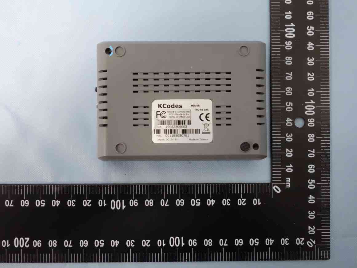
U9XKCODES-612
Apr 12, 2020Wireless USB Device
Equipment Class
DTS - Digital Transmission System
U9XKCODES-901
Nov 04, 2014KCodes 9 Series USB AirPrint Server
Equipment Class
DTS - Digital Transmission System
U9XKCODES-604N
Dec 27, 2010KCodes 4-port Wireless USB Device Server
Equipment Class
DTS - Digital Transmission System
U9XKCODES-601N
Dec 27, 2010KCodes 1-port Wireless USB Device Server
Equipment Class
DTS - Digital Transmission System
U9XKCODES-502G
May 29, 2007Multi Function Router
Equipment Class
DTS - Digital Transmission System