UB8-DLB5000Module for DLB5000 Radios
Deliberant LLC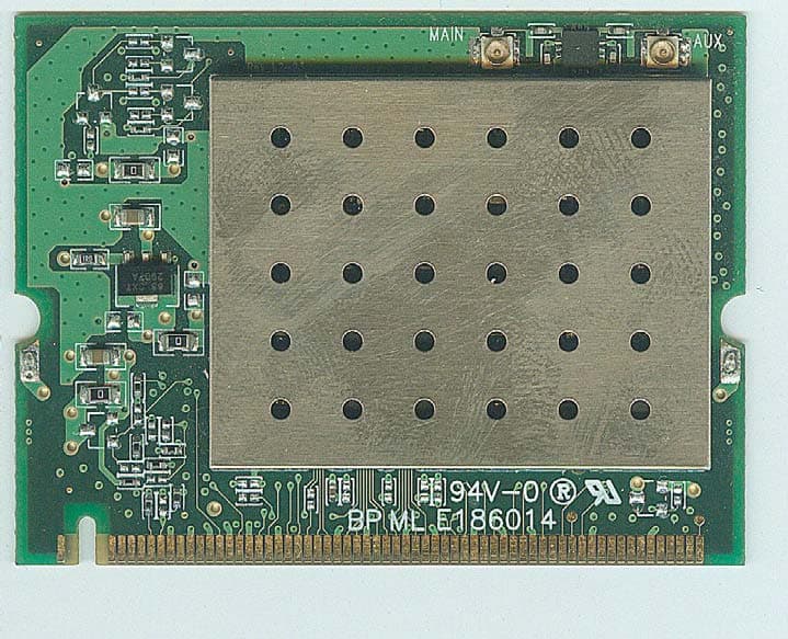
Click to zoom
Application Details
- Equipment Class
- DTS - Digital Transmission System
- Date of Grant
- Sep 17, 2007
- Application Purpose
- Original Equipment
- Date of Application
- Sep 17, 2007
- Equipment Note
- Module for DLB5000 Radios
- Frequency Range
- 5745.00000000 - 5825.00000000
- Company
- Deliberant LLC
- Country
- United States
Documents & Files
Document Text
Text extracted from the exhibit documents filed with the FCC. Open a document above to read the original.
Users Manual
Quick Install Guide Compex Wireless Mini PCI Adapter WLM54G 1A WLM54G 1B WLM54G 1C WLM54AG 1A WLM54AG 1B WLM54AG 1C WLM54G 6A (RoHS compliant) WLM54G 6B (RoHS compliant) WLM54G 6C (RoHS compliant) WLM54AG 6A (RoHS compliant) WLM54AG 6B (RoHS compliant) WLM54AG 6C (RoHS compliant) Version 1.2 1. Introduction This mini PCI adapter contains a dual-mode single chip MAC/BB/Radio for IEEE 802.11a or b/g Wireless LAN. Based on the latest industry standard Wi- Fi Certified IEEE 802.11a or b/g specifications, the mini PCI adapter supports key security features like Wi-Fi Protected Access (WPA), WPA2, WEP and 802.1x. The mini PCI adapter has four variants in its family: • WLM54G: This mini PCI adapter’s “G” chipset offers maximum channel speeds of up to 54Mbps in the frequency band of 2.4 GHz based on 802.11b/g. • WLM54AG: This mini PCI adapter’s “AG” chipset offers maximum channel speeds of up to 54Mbps in the frequency bands of 2.4 GHz and 5 GHz based on 802.11b/g and 802.11a respectively. You can find this adapter that is seated inside the wireless products such as the notebook computers or any other devices containing Mini PCI socket. The PCI adapter can be removed from or inserted on the PCBA of the Compex products. 2. Packaging Contents The PCI adapter’s retail package contains the following item(s): • 1 x Wireless Mini PCI adapter 3. Application Align the PCI adapter to the Mini PCI socket. Adjust and push down the PCI adapter gently until the metal- locking levers aside from the Mini PCI socket is fastened. (Please take note that the PCI adapter can only fit in one direction due to the keyed notch. Wrong orientation will cause improper installation and may damage the Mini PCI socket ! ). Connect the antenna(s) on the PCI adapter. Further Information References This document may become superseded, in which case you may find its latest version at: http://www.compex.com.sg iWave n o p Figure 1 WLM54AG 1A/1B/1C Disclaimer: Compex, Inc. provides this guide without warranty of any kind, either expressed or implied, including but not limited to the implied warranties of merchantability and fitness for a particular purpose. Compex, Inc. may make improvements and/or changes to the product and/or specifications of the product described in this guide, without prior notice. Compex, Inc. will not be liable for any technical inaccuracies or typographical errors found in this guide. Changes are periodically made to the information contained herein and will be incorporated into later versions of the guide. The information contained is subject to change without prior notice. Trademark Information: Compex ® , ReadyLINK ® and MicroHub ® are registered trademarks of Compex, Inc. Microsoft Windows and the Windows logo are the trademarks of Microsoft Corp. NetWare is the registered trademark of Novell Inc. All other brand and product names are trademarks or registered trademarks of their respective owners. Notice: Copyright © 2006 by Compex, Inc. All rights reserved. Reproduction, adaptation, or translation without prior permission of Compex, Inc. is prohibited, except as allowed under the copyright laws. Manual Revision by Daniel Manual Number: M-0559-V1.2C Version 1.2, November 2006 Warning: This device complies with part 15 of the FCC Rules. Operation is subject to the following two conditions: (1) This device may not cause harmful interference, and (2) this device must accept any interference received, including interference that may cause undesired operation. FCC NOTICE: This device has been tested and found to comply with the limits for a Class B digital device, pursuant to Part 15 of the FCC Rules. These limits are designed to provide reasonable protection against harmful interference in a residential installation. This device generates, uses and can radiate radio frequency energy. If not installed and used in accordance with the instructions, may cause harmful interference to radio communications. However, there is no guarantee that interference will not occur in a particular installation. If this device does cause harmful interference to radio or television reception which can be determined by turning the PC off and on, the user is encouraged to try to correct the interference by one or more of the following measures: RF exposure warning: This equipment must be installed and operated in accordance with provided instructions and the antenna(s) used for this transmitter must be installed to provide a separation distance of at least 6cm from all persons and must not be co-located or operating in conjunction 62.4cm wth any other antenna or transmitter. End-users and installers must be provide with antenna installation instructions and transmitter operating conditions for satisfying RF exposure compliance. Caution: The device is only for fixed point ot point communication. Reorient or relocate the receiving antenna. Connect the computer into an outlet on a circuit different from that to which the receiver is connected. Increase the distance between the computer and receiver. Consult the dealer or an experienced radio/TV technician for help. Caution: Any changes or modifications not expressly approved by the grantee of this device could void the user's authority to operate the equipment. FCC Compliance Statement: This device complies with Part 15 of the FCC Rules. Operation is subject to the following two conditions: ICES 003 Statement This Class B digital apparatus complies with Canadian ICES-003. DECLARATION OF CONFORMITY: Compex, Inc. declares that the product: Product Name: Compex Wireless Mini PCI Adapter Model No.: WLM54G 1a, WLM54G 1b, WLM54AG 1a, WLM54AG 1b conforms to the following Product Standards: Radiated Emission Standards: EN55022A, FCC Part 15 Class B Conducted Emission Standards: EN60555Pt2 conducted emission; EN55022A conducted emission, FCC Part 15 Class B Immunity Standards: IEC 801-2; IEC 801-3; IEC 801-4 Therefore, this product is in conformity with the following regional standa…
Text truncated - open the document above for the full version.
Cover Letter(s)
DELIBERANT LLC Date: August 10, 2007 Federal Communications Commission Authorization and Evaluation Division FCC ID: UB8-DLB5000 Confidentiality Request Pursuant to Sections 0.457 and 0.459 of the Commission’s Rules, the Applicant hereby requests confidential treatment of information accompanying this Application as outlined below: 1 Schematics 2 Block Diagram 3 Operational Description The above materials contain trade secrets and proprietary information not customarily released to the public. The public disclosure of these matters might be harmful to the Applicant and provide unjustified benefits to its competitors. The Applicant understands that pursuant to Rule 0.457, disclosure of this Application and all accompanying documentation will not be made before the date of the Grant for this application. Sincerely, Harold Bledsoe/manager DELIBERANT LLC
Cover Letter(s)
DELIBERANT LLC 1440 DUTCH VALLEY PLACE SUITE 730 ATLANTA,GA30324 TEL:800.742.9865 TRANSMITTER MODULAR APPROVAL ATTESTATION August 29,2007 Federal Communications Commission Re: Application Modular Approval Certification for FCC ID: UB8-DLB5000 Gentlemen: The following attestation addresses the eight requirements to support modular approval as required by the FCC Public Notice (DA –1407)“Part 15 Unlicensed Modular Transmitter Approval” 1 The modular transmitter has its own RF shielding and does not rely upon the shielding provided by the device into which it is installed in order to comply with Part 15 limits. 2 The modular transmitter has buffered modulation/data inputs. All inputs to the modules are buffered through the radio circuitry. 3 The modular transmitter has its own power supply regulator. 4 The modular transmitter has an antenna that complies with section 15.203 and 15.204(c) of the FCC rules. It has a UFL type of connector at the transmitter end and is soldered to the antenna (depending on OEM configuration). Also the antenna will be internal in the OEM host equipment and inaccessible to the user. 5 The modular transmitter was tested outside of a host desktop computer using a PCI extender card. The PCI extender card allows the transmitter to be placed outside of the chassis of the host desktop computer. 6 The modular transmitter will be labeled with its own FCC ID. Also the OEM host computer manufacturer will be informed to display a label referring to the enclosed module. The exterior label will read as follows: “Contains Transmitter Module FCC ID:UB8-DLB5000” or “Contains FCC ID:UB8-DLB5000”. 7 The modular transmitter is manufactured so that the user cannot influence the operation of the transmitter that will operate outside of the scope of the regulations. The end users 8 The modular transmitter meets the MPE calculations of 47 CFR 1.1307(b)(1). If there are any additional questions or if further information is needed, please contact us at your earliest convenience at 800.742.9865 Sincerely; Harold Bledsoe/President
External Photos
Module for DLB5000 Radios (M/N: DLB5000 Module-19dBi, DLB5000 Module-23dBi, DLB5000 Module) ¾ EUT Photograph – External Photographs (1) EUT Photo (2) EUT Photo (3) EUT Photo (4) EUT Photo (5) EUT Photo (6) EUT Photo (7) EUT Photo (Dipole Antenna 4.5/7dBi for 2.4G/5G)
ID Label/Location Info
(Module for DLB5000 Radios) FCC ID Label
ID Label/Location Info
Module for DLB5000 Radios (M/N:DLB5000 Module-19dBi, DLB5000 Module-23dBi, DLB5000 Module) FCC Label Position
Internal Photos
Module for DLB5000 Radios (M/N: DLB5000 Module-19dBi, DLB5000 Module-23dBi, DLB5000 Module) ¾ EUT Photograph – internal Photographs (1) EUT Photo (2) EUT Photo (3) EUT Photo (4) EUT Photo (5) EUT Photo (6) EUT Photo (7) EUT Photo (Dipole Antenna 4.5/7dBi for 2.4G/5G)
RF Exposure Info
RF Exposure Evaluation declaration Product Name : Module for DLB5000 Radios Model No. : DLB5000 Module-19dBi, DLB5000 Module-23dBi, DLB5000 Module FCC ID : UB8-DLB5000 Applicant : DELIBERANT LLC Address : 1440 DUTCH VALLEY PLACE SUITE 730 ATLANTA, GA30324 Date of Receipt : 2007/06/15 Issued Date : 2007/09/17 Report No. : 076S047-RF-US The test results relate only to the samples tested. The test results shown in the test report are traceable to the national/international standard through the calibration of the equipment and evaluated measurement uncertainty herein. This report must not be used to claim product endorsement by CNLA, NVLAP, NIST or any agency of the Government. The test report shall not be reproduced except in full without the written approval of QuieTek Corporation. Report No: 076S047-RF-US Page: 2 of 8 1. RF Exposure Evaluation 1.1. Limits According to FCC 1.1310: The criteria listed in the following table shall be used to evaluate the environment impact of human exposure to radio frequency (RF) radiation as specified in 1.1307(b) LIMITS FOR MAXIMUM PERMISSIBLE EXPOSURE (MPE) Frequency Range (MHz) Electric Field Strength (V/m) Magnetic Field Strength (A/m) Power Density (mW/cm2) Average Time (Minutes) (A) Limits for Occupational/ Control Exposures 300-1500 -- -- F/300 6 1500-100,000 -- -- 5 6 (B) Limits for General Population/ Uncontrolled Exposures 300-1500 -- -- F/1500 6 1500-100,000 -- -- 1 30 F= Frequency in MHz Friis Formula Friis transmission formula: Pd = (Pout*G)/(4*pi*r2) Where Pd = power density in mW/cm2 Pout = output power to antenna in mW G = gain of antenna in linear scale Pi = 3.1416 R = distance between observation point and center of the radiator in cm Pd id the limit of MPE, 1 mW/cm2 . If we know the maximum gain of the antenna and the total power input to the antenna, through the calculation, we will know the distance r where the MPE limit is reached. Report No: 076S047-RF-US Page: 3 of 8 1.2. Test Procedure Software provided by client enabled the EUT to transmit and receive data at lowest, middle and highest channel individually. The temperature and related humidity: 18°Cand 78% RH. 1.3. Test Result of RF Exposure Evaluation Product : Module for DLB5000 Radios Test Item : RF Exposure Evaluation Test Site : AC-3 Test Mode : Mode 1: Transmitter by 802.11b (19 dBi Antenna) Antenna Gain: Antenna Gain: The maximum Gain measured in fully anechoic chamber is 19 dBi or 79.43 in linear scale. Output Power Into Antenna & RF Exposure Evaluation Distance: Channel Channel Frequency (MHz) Output Power to Antenna (mW) RF Exposure Distance (cm) 01 2412.00 244.9063 39.355477 06 2437.00 239.8833 38.949795 11 2462.00 239.8833 38.949795 Report No: 076S047-RF-US Page: 4 of 8 Product : Module for DLB5000 Radios Test Item : RF Exposure Evaluation Test Site : AC-3 Test Mode : Mode 1: Transmitter by 802.11b (4.5 dBi Antenna) Antenna Gain: Antenna Gain: The maximum Gain measured in fully anechoic chamber is 4.5 dBi or 2.82 in linear scale. Output Power Into Antenna & RF Exposure Evaluation Distance: Channel Channel Frequency (MHz) Output Power to Antenna (mW) RF Exposure Distance (cm) 01 2412.00 244.9063 7.4131908 06 2437.00 239.8833 7.3367747 11 2462.00 239.8833 7.3367747 Report No: 076S047-RF-US Page: 5 of 8 Product : Module for DLB5000 Radios Test Item : RF Exposure Evaluation Test Site : AC-3 Test Mode : Mode 2: Transmitter by 802.11g (19 dBi Antenna) Antenna Gain: Antenna Gain: The maximum Gain measured in fully anechoic chamber is 19 dBi or 79.43 in linear scale. Output Power Into Antenna & RF Exposure Evaluation Distance: Channel Channel Frequency (MHz) Output Power to Antenna (mW) RF Exposure Distance (cm) 01 2412.00 319.1538 44.926768 06 2437.00 312.6079 44.463657 11 2462.00 258.2260 40.411519 Report No: 076S047-RF-US Page: 6 of 8 Product : Module for DLB5000 Radios Test Item : RF Exposure Evaluation Test Site : AC-3 Test Mode : Mode 2: Transmitter by 802.11g (4.5 dBi Antenna) Antenna Gain: Antenna Gain: The maximum Gain measured in fully anechoic chamber is 4.5 dBi or 2.82 in linear scale. Output Power Into Antenna & RF Exposure Evaluation Distance: Channel Channel Frequency (MHz) Output Power to Antenna (mW) RF Exposure Distance (cm) 01 2412.00 319.1538 8.4626266 06 2437.00 312.6079 8.3753927 11 2462.00 258.2260 7.6121122 Report No: 076S047-RF-US Page: 7 of 8 Product : Module for DLB5000 Radios Test Item : RF Exposure Evaluation Test Site : AC-3 Test Mode : Mode 3: Transmitter by 802.11a (23 dBi Antenna) Antenna Gain: Antenna Gain: The maximum Gain measured in fully anechoic chamber is 23 dBi or 199.53 in linear scale. Output Power Into Antenna & RF Exposure Evaluation Distance: Channel Channel Frequency (MHz) Output Power to Antenna (mW) RF Exposure Distance (cm) 01 5745.00 244.9063 62.374228 03 5785.00 211.8361 58.010309 05 5825.00 209.4112 57.677334 Report No: 076S047-RF-US Page: 8 of 8 Product : Module for DLB5000 Radios Test Item : RF Exposure Evaluation Test Site : AC-3 Test Mode : Mode 3: Transmitter by 802.11a (7 dBi Antenna) Antenna Gain: Antenna Gain: The maximum Gain measured in fully anechoic chamber is 7 dBi or 5.01 in linear scale. Output Power Into Antenna & RF Exposure Evaluation Distance: Channel Channel Frequency (MHz) Output Power to Antenna (mW) RF Exposure Distance (cm) 01 5745.00 244.9063 9.8856489 03 5785.00 211.8361 9.1940144 05 5825.00 209.4112 9.1412415
Test Report
Test Report Product Name : Module for DLB5000 Radios Model No. : DLB5000 Module-19dBi, DLB5000 Module-23dBi, DLB5000 Module FCC ID : UB8-DLB5000 Applicant : DELIBERANT LLC Address : 1440 DUTCH VALLEY PLACE SUITE 730 ATLANTA, GA30324 Date of Receipt : 2007/06/15 Issued Date : 2007/09/17 Report No. : 076S047-RF-US-P05V01 The test results relate only to the samples tested. The test results shown in the test report are traceable to the national/international standard through the calibration of the equipment and evaluated measurement uncertainty herein. This report must not be used to claim product endorsement by CNLA, NVLAP, NIST or any agency of the Government. The test report shall not be reproduced except in full without the written approval of QuieTek Corporation. Report No: 076S047-RF-US-P05V01 Page: 2 of 257 Test Report Certification Issued Date : 2007/09/17 Report No. : 076S047-RF-US-P05V01 Product Name : Module for DLB5000 Radios Applicant : DELIBERANT LLC Address : 1440 DUTCH VALLEY PLACE SUITE 730 ATLANTA, GA30324 Manufacturer : DELIBERANT LLC Model No. : DLB5000 Module-19dBi, DLB5000 Module-23dBi, DLB5000 Module FCC ID : UB8-DLB5000 Rated Voltage : AC 120V/60Hz EUT Voltage : DC 3.3V Trade Name : Deliberant Applicable Standard : FCC CFR Title 47 Part 15 Subpart C: 2007 ANSI C63.4: 2003 Test Result : Complied Performed Location : SuZhou EMC laboratory No.99 Hongye Rd., Suzhou Industrial Park Loufeng Hi-Tech Development Zone., SuZhou, China TEL: +86-512-6251-5088 / FAX: +86-512-6251-5098 FCC Registration number: 800392 Documented By : ( Mandy Liu ) Reviewed By : ( Dream Cao ) Approved By : ( Murphy Wang ) Report No: 076S047-RF-US-P05V01 Page: 3 of 257 Laboratory Information We , QuieTek Corporation, are an independent EMC and safety consultancy that was established the whole facility in our laboratories. The test facility has been accredited by the following accreditation Bodies in compliance with ISO 17025, EN 45001 and Guide 25: The related certificate for our laboratories about the test site and management system can be downloaded from QuieTek Corporation’s Web Site : http://tw.quietek.com/modules/myalbum/ The address and introduction of QuieTek Corporation’s laboratories can be founded in our Web site : http://www.quietek.com/ If you have any comments, Please don’t hesitate to contact us. Our contact information is as below: HsinChu Testing Laboratory : No.75-2, 3rd Lin, Wangye Keng, Yonghxing Tsuen, Qionglin Shiang, Hsinchu County 307, Taiwan, R.O.C. TEL:+886-3-592-8858 / FAX:+886-3-592-8859 E-Mail : [email protected] LinKou Testing Laboratory : No. 5-22, Ruei-Shu Valley, Ruei-Ping Tsuen, Lin-Kou Shiang, Taipei, Taiwan, R.O.C. TEL : 886-2-8601-3788 / FAX : 886-2-8601-3789 E-Mail : [email protected] Suzhou Testing Laboratory : No.99 Hongye Rd., Suzhou Industrial Park Loufeng Hi-Tech Development Zone., SuZhou, China TEL : +86-512-6251-5088 / FAX : 86-512-6251-5098 E-Mail : [email protected] Taiwan R.O.C. : BSMI, DGT, CNLA Germany : TUV Rheinland Norway : Nemko, DNV USA : FCC, NVLAP Japan : VCCI 0914 1313 1596 Report No: 076S047-RF-US-P05V01 Page: 4 of 257 TABLE OF CONTENTS Description Page 1. General Information .................................................................................................... 6 1.1. EUT Description...................................................................................................... 6 1.2. Mode of Operation .................................................................................................. 8 1.3. Tested System Details ............................................................................................ 9 1.4. Configuration of Tested System............................................................................ 10 1.5. EUT Exercise Software......................................................................................... 11 2. Technical Test ........................................................................................................... 12 2.1. Summary of Test Result........................................................................................ 12 2.2. Test Environment .................................................................................................. 13 3. Conducted Emission................................................................................................. 14 3.1. Test Equipment .....................................................................................................14 3.2. Test Setup............................................................................................................. 14 3.3. Limit..................................................................................................................... 15 3.4. Test Procedure ..................................................................................................... 15 3.5. Uncertainty ........................................................................................................... 15 3.6. Test Result ............................................................................................................ 16 4. Radiated Emission .................................................................................................... 52 4.1. Test Equipment .....................................................................................................52 4.2. Test Setup............................................................................................................. 52 4.3. Limit..... ................................................................................................................53 4.4. Test Procedure ..................................................................................................... 54 4.5. Uncertainty ........................................................................................................... 54 4.6. Test Result ........................................................................…
Text truncated - open the document above for the full version.
Test Setup Photos
Page: 1 of 21 Wireless- Module for DLB5000 Radios (M/N: DLB5000 MODULE-19dBi, DLB5000 Module-23dBi, DLB5000 Module) ¾ Test Setup Photographs for Conducted Emission Test Mode: Mode 1: Transmit by 802.11b (19dBi) Description: Front View of Conduction Test Page: 2 of 21 Test Mode: Mode 1: Transmit by 802.11b (19dBi) Description: Back View of Conduction Test Test Mode: Mode 1: Transmit by 802.11b (4.5dBi) Description: Front View of Conduction Test Page: 3 of 21 Test Mode: Mode 1: Transmit by 802.11b (4.5dBi) Description: Back View of Conduction Test Test Mode: Mode 2: Transmit by 802.11g (19dBi) Description: Front View of Conduction Test Page: 4 of 21 Test Mode: Mode 2: Transmit by 802.11g (19dBi) Description: Back View of Conduction Test Test Mode: Mode 2: Transmit by 802.11g (4.5dBi) Description: Front View of Conduction Test Page: 5 of 21 Test Mode: Mode 2: Transmit by 802.11g (4.5dBi) Description: Back View of Conduction Test Test Mode: Mode 3: Transmit by 802.11a (23dBi) Description: Front View of Conduction Test Page: 6 of 21 Test Mode: Mode 3: Transmit by 802.11a (23dBi) Description: Back View of Conduction Test Test Mode: Mode 3: Transmit by 802.11a (7dBi) Description: Front View of Conduction Test Page: 7 of 21 Test Mode: Mode 3: Transmit by 802.11a (7dBi) Description: Back View of Conduction Test Page: 8 of 21 ¾ Test Setup Photographs for Radiated Emission Test Mode: Mode 1: Transmit by 802.11b (19dBi) Description: Front View of Radiated Test for Under 1GHz Test Mode: Mode 1: Transmit by 802.11b (19dBi) Description: Back View of Radiated Test for Under 1GHz Page: 9 of 21 Test Mode: Mode 1: Transmit by 802.11b (19dBi) Description: Front View of Radiated Test for Above 1GHz Test Mode: Mode 1: Transmit by 802.11b (19dBi) Description: Back View of Radiated Test for Above 1GHz Page: 10 of 21 Test Mode: Mode 1: Transmit by 802.11b (4.5dBi) Description: Front View of Radiated Test for Under 1GHz Test Mode: Mode 1: Transmit by 802.11b (4.5dBi) Description: Back View of Radiated Test for Under 1GHz Page: 11 of 21 Test Mode: Mode 1: Transmit by 802.11b (4.5dBi) Description: Front View of Radiated Test for Above 1GHz Test Mode: Mode 1: Transmit by 802.11b (4.5dBi) Description: Back View of Radiated Test for Above 1GHz Page: 12 of 21 Test Mode: Mode 2: Transmit by 802.11g (19dBi) Description: Front View of Radiated Test for Under 1GHz Test Mode: Mode 2: Transmit by 802.11g (19dBi) Description: Back View of Radiated Test for Under 1GHz Page: 13 of 21 Test Mode: Mode 2: Transmit by 802.11g (19dBi) Description: Front View of Radiated Test for Above 1GHz Test Mode: Mode 2: Transmit by 802.11g (19dBi) Description: Back View of Radiated Test for Above 1GHz Page: 14 of 21 Test Mode: Mode 2: Transmit by 802.11g (4.5dBi) Description: Front View of Radiated Test for Under 1GHz Test Mode: Mode 2: Transmit by 802.11g (4.5dBi) Description: Back View of Radiated Test for Under 1GHz Page: 15 of 21 Test Mode: Mode 2: Transmit by 802.11g (4.5dBi) Description: Front View of Radiated Test for Above 1GHz Test Mode: Mode 2: Transmit by 802.11g (4.5dBi) Description: Back View of Radiated Test for Above 1GHz Page: 16 of 21 Test Mode: Mode 3: Transmit by 802.11a (23dBi) Description: Front View of Radiated Test for Under 1GHz Test Mode: Mode 3: Transmit by 802.11a (23dBi) Description: Back View of Radiated Test for Under 1GHz Page: 17 of 21 Test Mode: Mode 3: Transmit by 802.11a (23dBi) Description: Front View of Radiated Test for 1-18GHz Test Mode: Mode 3: Transmit by 802.11a (23dBi) Description: Back View of Radiated Test for 1-18GHz Page: 18 of 21 Test Mode: Mode 3: Transmit by 802.11a (23dBi) Description: Front View of Radiated Test for 18-40GHz Test Mode: Mode 3: Transmit by 802.11a (23dBi) Description: Back View of Radiated Test for 18-40GHz Page: 19 of 21 Test Mode: Mode 3: Transmit by 802.11a (7dBi) Description: Front View of Radiated Test for Under 1GHz Test Mode: Mode 3: Transmit by 802.11a (7dBi) Description: Back View of Radiated Test for Under 1GHz Page: 20 of 21 Test Mode: Mode 3: Transmit by 802.11a (7dBi) Description: Front View of Radiated Test for 1-18GHz Test Mode: Mode 3: Transmit by 802.11a (7dBi) Description: Back View of Radiated Test for 1-18GHz Page: 21 of 21 Test Mode: Mode 3: Transmit by 802.11a (7dBi) Description: Front View of Radiated Test for 18-40GHz Test Mode: Mode 3: Transmit by 802.11a (7dBi) Description: Back View of Radiated Test for 18-40GHz
Contact Information
Applicant
Simon Chou(General Manager)
Test Firm
DEKRA TESTING AND CERTIFICATION CO., LTD. LinKouMirenda Liao
Technical Specifications
| # | Rule Parts | Frequency Range | Power Output |
|---|---|---|---|
| 2 | 15C | 5.75 GHz - 5.83 GHz | 240.00 mW |
Other Applications from Deliberant LLC

UB8-FWBD1102
Nov 11, 2014Broadband Digital Transmission System
Equipment Class
NII - Unlicensed National Information Infrastructure TX
UB8-FWBD1907
Oct 08, 2014Broadband Digital Transmission Module
Equipment Class
DTS - Digital Transmission System
UB8-ECHO5
Sep 01, 2014Broadband Digital Transmission System
Equipment Class
DTS - Digital Transmission System
UB8-NFT2N
Aug 22, 2014Broadband Digital Transmission System
Equipment Class
DTS - Digital Transmission System
UB8-SPTNK5
Jul 09, 2013Broadband Digital Transmission System
Equipment Class
DTS - Digital Transmission System