UK3-F172FM Transmitter
Daza Technology Electronics
Click to zoom
Application Details
- Equipment Class
- DXX - Part 15 Low Power Communication Device Transmitter
- Date of Grant
- Dec 15, 2009
- Application Purpose
- Original Equipment
- Date of Application
- Dec 15, 2009
- Equipment Note
- FM Transmitter
- Frequency Range
- 88.10000000 - 107.90000000
- Company
- Daza Technology Electronics
- Country
- China
Documents & Files
Document Text
Text extracted from the exhibit documents filed with the FCC. Open a document above to read the original.
Users Manual
1 F-172 Transmitter (MP3 Player) USER MANUAL F-172 Feature • Supply SD card, USB input and audio jack to connect with MP3/MP4. • Supply MP3 and WMA format. • Read USB and SD card directly. • LED display – shows frequency information. • Full frequencies closeable (88.1 – 107.9 MHz). • Frequency and song memory function. • Save transmitting frequency and broadcast. • Use of rotating shaft: convenient use. • Fashion and attractive appearance. • Restored last frequency, track number and volume by restart. Operation 1. Insert transmitter to 12V car cigarette socket power. 2. USB/SD card insert to USB/SD card jack; or using audio-line end to connect to transmitter; the other end connect to other equipment’s audio output jack (e.g.: MP3, CD) 3. When connected, transmitter plays music automatically and display shows the frequency. About 30 seconds the screen will turn off automatically. By pressing any key display is recovered. By pressing the LED flashes. 4. “CH” key switchs between emission frequency and selected song. Press key while music plays: display shows current frequency. Press key: frequency moves to the next point. Press key: frequency moves to previous point. 5. By pressing button: broadcasting music pauses; pressing again resumes playing. 6. By pressing key: previous program plays. By pressing the key for some seconds, volume is reduced. 7. By pressing key: broadcast of next program. By pressing the key for some seconds, volume is increased. 8. No audio signal: device shut down automatically after 55 seconds. 2 Declaration of Conformity This device complies with part 15 of the FCC rules. Operation is subject to the following two conditions: (1) this device may not cause harmful interference, and (2) this device must accept any interference received, including interference that may cause undesired operation of the device. Modification Statatement changes or modifications not expressly approved by the party responsible for compliance could void the user's authority to operate the equipment. NOTE: This equipment has been tested and found to comply with the limits for a Class B digital device, pursuant to Part 15 of the FCC Rules. These limits are designed to provide reasonable protection against harmful interference in a residential installation. This equipment generates, uses and can radiate radio frequency energy and, if not installed and used in accordance with the instructions, may cause harmful interference to radio communications. However, there is no guarantee that interference will not occur in a particular installation. If this equipment does cause harmful interference to radio or television reception, which can be determined by turning the equipment off and on, the user is encouraged to try to correct the interference by one or more of the following measures: -- Reorient or relocate the receiving antenna. -- Increase the separation between the equipment and receiver. -- Connect the equipment into an outlet on a circuit different from that to which the receiver is connected. -- Consult the dealer or an experienced radio/TV technician for help. 3 20 Key Remote Control Play / Pause Start / Stop the music CH ( -- ) Frequency down CH ( + ) Frequency up EQ Changes sound characteristic: Normal (default) Æ Rock Æ Pop Æ Classic Æ Jazz Æ Blues Æ Hall Æ Bass Æ Soft Æ Country Æ Opera Volume ( -- ) Volume down Volume ( + ) Volume up PREV Previous track NEXT Next track 0123456789 Number keys for setting the frequency and picking songs Pick Song Confirms picking a song after selection with the number keys CH Set Confims setting the frequency after selection with the number keys Operation Illustration: 1. The FM Transmitter has 206 frequencies (88.1 – 107.9 MHz) to use. Usage of the number keys (0-9) to select a frequency. Then press CH SET key to confirm and save the frequency. 2. Usage of the number keys (0-9) to select the music track number. Then press PICK SONG key to confirm. 3. Every time EQ is pressed the sound characteristics are changed: NORMAL (default setting) Æ ROCK Æ POP Æ CLASSIC Æ JAZZ Æ BLUES Æ HALL Æ BASS Æ SOFT Æ COUNTRY Æ OPERA. Press long EQ key and the system returns back to NORMAL. 4 4. Last settings for volume, FM-transmission-frequency and music track are stored when the device is powered off. 5. USB and SD-card can both be connected to the device. The first medium connected, either USB or SD-card, is played. To select the other medium, the first one must be disconnected. 6. When an external audio device is connected to the audio-in jack, the playback from USB or SD-card stopps automatically and cannot be started or paused by pressing the PLAY/PAUSE button. Replacing the Remote Control Battery 1) Remove the battery compartment cover by pulling the cover in the direction of the arrow. 2) Remove the battery. 3) Insert the replacement battery. Keep attention on the direction of the correct polarization (+/-). 4) Put the cover back to the battery compartment. 5 Technical Parameters ◆ Storage temperature: -5°C up to +45°C ◆ Working conditions temperature: 0°C up to +40°C ◆ Operation relative humidity: 20% - 90% (40°C) ◆ Storage relative humidity: 20% - 93% (40°C) ◆ EMI standard: FCC (class B) ◆ Supply voltage: 12V DC power ◆ Electric current: 12V (normal working)<100mA ◆ Bit rate: 32Kbps – 256Kbps ◆ FM transmitting frequency: 88.1 – 107.9 MHz ◆ Transmitting frequency options: Press CH key to switch channels (can be stored in advance). ◆ Frequency response: 30 – 15 KHz ± 3db ◆ SNR (Signal to Noise Ratio): 30db ◆ Harmonic distortion: ≤1% ◆ Transmitting distance: 3 – 5 m ◆ For continuing broadcast: Programme starts broadcast again from last stop. Security and Disposal Hints for Batteries • Hold children off batteries. When a child swallowed a battery by mistake go to a doctors place or bring the child into a hospital promtly! • Never short batteries. • Look for the right polarity ( +) and (▬) of batteries! Always change all batteries, never use old and new batteries…
Text truncated - open the document above for the full version.
Attestation Statements
Daza Technology Electronics Room 1410-1411, Block A, Jiah Bldg, Shennan Mid-road, Futian District, Shenzhen, China (2009-12-10) To: Federal Communications Commission 7435 Oakland Mills Road Columbia, MD FCC ID: To Whom It May Concern: This letter is to ascertain that _Daza Technology Electronics . Product FM Modulator Model:F-172 has been the units used for conducting FCC compliance testing, the DoC part will be tested by FCC recognized test lab. If you have any question or concerns, pls. contact us. Sincerely, Client’s signature: Client’s name / title Longbiao Lei Contact information / address Daza Technology Electronics Room 1410-1411, Block A, Jiah Bldg, Shennan Mid-road, Futian District, Shenzhen, China
Block Diagram
Ant.88.1-107.9MHz SD/USB DC-DC 34063 TXBK1085 MCU1X2005 AX3008 CRYSTAL 7.6MHz KEY ADUIO
Cover Letter(s)
SCS-F18: Project and Product Certification Representative Authorization Letter Page 1 of 2 Rev 2.0 2206 Ringwood Avenue San Jose, CA 95131 Tel: 408-526-1188 Fax: 408-526-1088 Email: [email protected] Project and Product Certification Representative Authorization Letter Revision History Reason for Amendment (current / obsolete) From To Approved Date Initial Release (current) 1.0 1.0 Nov-14-2006 Revised wording (current) 1.0 2.0 Sept–25-2007 SCS-F18: Project and Product Certification Representative Authorization Letter Page 2 of 2 Rev 2.0 Daza Technology Electronics Room 1410-1411, Block A, Jiah Bldg, Shennan Mid-road, Futian District, Shenzhen, China (2009-12-10) To: SIEMIC, INC. 2206 Ringwood Avenue, San Jose, CA 95131 USA Dear Sir/Madam, Re: Project and Product Certification Representative Authorization Letter We, _Daza Technology Electronics __hereby authorize SIEMIC, INC. to act as a Certification Body for certifying for the following project(s): FM Modulator Model:F-172 We affirm that between SIEMIC and _ Daza Technology Electronics ____, any difference in understanding, including test plan, measurement methods, applicable standards and relevant procedures and processes have been resolved prior to commencement of testing activities. Sincerely, Client’s signature: Client’s name / title Longbiao Lei Contact information / address Daza Technology Electronics Room 1410-1411, Block A, Jiah Bldg, Shennan Mid-road, Futian District, Shenzhen, China
Cover Letter(s)
1) How does this device operate? USB/SD card insert to USB/SD card jack; or using audio-line end to connect to transmitter; the other end connect to other equipment’s audio output jack (e.g.: MP3, CD). and powered from Car Cigarette socket. By pressing any key display 2) Provide information on the device and its antenna. The transmitter’s antenna is same cable as Power line from Car Cigarette, this is permanently attached antenna and meets the requirements of the section. 3) How is it installed? The EUT will insert transmitter to 12V car cigarette socket power, and power by 12Vdc Car Power. 4) What test procedure was used? FCC Part 15 Paragraph 15.239, Paragraph 15.209 5) If tested in a car, how was it configured/tested? N/A 6) Was the tuning range properly verified? The test lab should indicate in the report that the tuning controls were manually adjusted to verify maximum tuning range. EUT was adjusted to work at the selected channels: 88.1 MHz, 98.1 MHz, and 107.9 MHz. The EUT will not allow operation below 88.1 MHz and will not allow operation above 107.9 MHz. 7) Was the bandwidth properly tested with maximum audio input? Emissions from the intentional radiator shall be confined within a band 200 kHz wide centered on the operation frequency. The 200 kHz band shall lie wholly within the frequency range of 88 – 108 MHz. Setup the EUT and simulators as shown in the report. Enable RF signal and confirm EUT active. Modulate output capacity of EUT up to specifications. 8) Provide the test report. Test Report Submitted. Signature : Name :Peter Xiao Title: Manager Telephone: 86+755-26966362 Email: [email protected] Date: 2009-12-9
External Photos
External photos
ID Label/Location Info
LabelInformation FM Modulator Model No.: F-172 FCC ID: UK3-F172 Country of Origin: China Daza Technology Electronics FCC Caution: This device complies with part 15 of the FCC rules. Operation is subject to the following two conditions: (1) this device may not cause harmful interference, and (2) this device must accept any interference received, including interference that may cause undesired operation of the device. Location FCC ID Label Location
Internal Photos
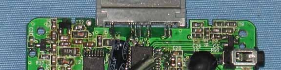
Internal Photos
Operational Description
Circuit Descricption MCU:IC-AX3008-SOP-48 U1-chip-based decoder IC, Model No. AX3008-SOP-48. It consists of Y1-7.6MHZ oscillator oscillation control plug-ins, the main decoding U disk \ SD card music files, their format, including MP3 and WMA formats. Another through the I \ O port control operation LED display and keypad, FM launch. Car MP3, FM eventually launch capabilities FM TX I C BK1085-SOP-16 KU1 chip FM launches IC, Model: BK1085-SOP-16. It is shared by a pin with the master oscillator plug-YI-7.6MHZ vibration control, 7 \ 8-pin for signal input; 9 \ 10-pin DATA control; 15 foot antenna outputs ANT, their hair-point range radio frequency adjustable in the 88.1-107.9MHZ. EEPROM IC 24C02-SOP-08 U2 small memory chip IC, the amount of memory 2KHZ.. Ontology for the memory function of a major role in the operation of the state. Such as: frequency song, volume and so on Power IC_TD34063-SOP-08 A major role in this power supply IC for DC-DC dropout regulators will soon be car battery's 12-24VDC input by 6 feet, IC internal step-down, voltage regulator, the constant voltage output from the two legs 5-5.4VDC, for the main circuit power usage
Schematics
44 33 22 11 4 4 3 3 2 2 1 1 SOT223 <Doc> 1.0 USB HOST MP3/WMA DECODER B 11 Monday, January 12, 2009 TitleSize Document Number Rev Date: Sheet of GP3 DP LED7 SCL FMCEDM LCHLEDS1GND FMCK VCC+5V FMDA GNDRCH SDA XI LEDS2LEDS3LEDS4LED0/K0LED1/K1LED2/K2LED3/K3LED4/K4LED5/K5LED6 XO LED4/K4LED2/K2 SDDO FMDADACL LED4/K4LED5/K5 SDDI SDCS XO SDA LED0/K0 LED3/K3 LEDS2FMCE VPP LEDS3LEDS4FMCK DACR LED2/K2 LEDS1 SDCLK DP LED1/K1 DM SCL LED6LED7 DACRDACL LED3/K3LED1/K1 GP2GP1GP0 FX XI RCHLCH FX FML FMCK FMDA FMR +1V8 ANT FMDA R FX ANT L FMCK RL VCC+5V VCC+3V3 VCC+5V VCC+3.3V VCC+3.3V VCC+3.3V VCC+3.3V VCC+3V3 S2Play/Pause AR2 4.7K R5 3.3K C160.1uF R2 3.3K C327pF U2AT24C02BN-SH 3124 5678 A2A0A1GND SDA SCL WP VCC C9472 R9 10K R7 3.3K S4CH R18 4K7 C2105 C140.1uF J26Pin 1234567 C60.1uF AC4 104 AC3 105 C427pF AMC1 10uF AC1 105 U1AX2005 1235746 13 9 15 1211 14 10 8 16 17 18 19 20 21 33343536 37 38 39 40 41 42 43 44 45 46 47 48 22 23 24 2526272829303132 OSIOSOP57LCHP51P56P54 P03 P07 P01 P04P05 P02 P06P50 P00 LDOVDD LDOVSS VPP LDOEN P41 P66P65P64P63 P62 P61 P60 VDDIO RCH COREVSS COREVDD P17 P14 P13 PLLVDD PLLVSS P40 P37 P36 Rest PTEST P32P31P30 DM DP P67 C10.1uF Y1 7.6M J1LED Indicator 121134105781296 R4 3.3K MC210uF R21 1K R114K7 AL1 220nH U3LDO3V3 2 3 1 Vout Vin GND R13 1K C150.1uF R16 4K7 AC2105 R19 4K7 C110.1uF J35Pin 12345 C42 100pF R3 3.3K AU1 AS6300 123456789 10 11121314151617181920 GNDVCCPVCCGNDLOILOOGNDCPRSTXI XO CKDA NCNC VCC GND PAOUT LCH RCH S1Prev./VolDown AR1 4.7K AC7 2nF R10 4K7 S3Next/VolUp C5105 IR1REM 312 VCCSGND AC8 1nF R153.3K AC6 105 R124K7 R6 3.3K R203.3K C120.1uF R1 3.3K TX1 MC110uF R17 4K7 AL2 39nH R8 3.3K AC5 6pF C130.1uF C7472 KR3 10K BL1 100nH KC233P KC1100nF KU1 BK1085 12345678 911101213141516 XIRSTXOGNDSELD0-2LCHRCH MOSI CSN SCK VDD5V GND VDD5V POUT PWD IR_IN VCC+3V3 VCC+3V3 VCC+3V3 VCC+3V3 VCC+3V3 VCC+3V3 VCC+3V3 IR_IN
Test Report
SHENZHEN SETEK TECHNOLOGY CO., LTD. Report No.: FCI0911022R Page 1 of 22 FCC TEST REPORT REPORT NO.: FCI0911022R MODEL NO.: F-172 RECEIVED: Nov. 02, 2009 TESTED: Nov. 03, 2009 to Nov. 23, 2009 APPLICANT: Daza Technology Electronics ADDRESS: Room 1410-1411, Block A, Jiah Bldg, Shennan Mid-road, Futian District, Shenzhen, China ISSUED BY: SHENZHEN SETEK TECHNOLOGY CO., LTD. LAB LOCATION: 2/F,A3 Bldg, East Industry Zone, Overseas Chinese Town, Shenzhen, China This test report consists of 22 pages in total, it may be duplicated completely for legal use with the approval of the applicant, It should not be reproduced except in full, without the written approval of our laboratory, The test results in the report only apply to the tested sample. SHENZHEN SETEK TECHNOLOGY CO., LTD. Our website: www.setek.com.cn E-mail: [email protected] TEL:86-755-26966362 FAX: 86-755-26966270 SHENZHEN SETEK TECHNOLOGY CO., LTD. Report No.: FCI0911022R The device described above is tested by SHENZHEN SETEK TECHNOLOGY CO., LTD. to determine the maximum emission levels emanating from the device and the severe levels of the device can endure and its performance criterion. This report applies to above tested sample only and shall not be reproduced in part without written approval of SHENZHEN SETEK TECHNOLOGY CO., LTD. Page 2 of 22 Prepared for : Daza Technology Electronics Address : Room 1410-1411, Block A, Jiah Bldg, Shennan Mid-road, Futian District, Shenzhen, China Product : FM Modulator Model No(s). : F-172 Trademark : N/A Test Standard : FCC Part 15 Paragraph 15.239, Paragraph 15.209 Prepared by : SHENZHEN SETEK TECHNOLOGY CO., LTD. Address : 2/F, A3 Bldg, East Industry Zone, Overseas Chinese Town, Shenzhen, China Tel: (86-755) 26966362 Fax:(86-755) 26966270 Test Lab : SEM Test Compliance Service Co., Ltd. Address : 3/F, Jinbao Commerce Bldg., Xin’an Fanshen Rd., Bao’an District, Shenzhen, P. R. China FCC R.N. : FCC Registration Number: 994117 Prepared by : (Engineer) Reviewer by : (Project Engineer) Approved by : (Manager) Report Number : FCI0911022R Date of Test : Nov. 03, 2009 to Nov. 23, 2009 Date of Report : Nov. 24, 2009 FCC ID : UK3-F172 SHENZHEN SETEK TECHNOLOGY CO., LTD. Report No.: FCI0911022R The device described above is tested by SHENZHEN SETEK TECHNOLOGY CO., LTD. to determine the maximum emission levels emanating from the device and the severe levels of the device can endure and its performance criterion. This report applies to above tested sample only and shall not be reproduced in part without written approval of SHENZHEN SETEK TECHNOLOGY CO., LTD. Page 3 of 22 TABLE OF CONTENTS Description Page The Report Description 1. GENERAL INFORMATION ............................................................................................................ 4 1.1. Description of Device (EUT) ................................................................................................................... 4 1.2. Description of test..................................................................................................................................... 5 1.3. Description of Support Device ................................................................................................................. 6 1.4. Summary of test results ............................................................................................................................ 6 1.5. List of Measuring Equipments Used ........................................................................................................ 7 1.6. Test Facility .............................................................................................................................................. 7 1.7. Measurement Uncertainty......................................................................................................................... 7 2. ANTENNA REQUIREMENT ......................................................................................................... 8 2.1. Standard Applicable ................................................................................................................................. 8 2.2. Antenna Connected Construction ............................................................................................................. 8 3. EMISSION BANDWIDTH TESTING ........................................................................................... 9 3.1. Test Equipment......................................................................................................................................... 9 3.2. Test Procedure .......................................................................................................................................... 9 3.3. Record of Test Result/Plots ...................................................................................................................... 9 4. RADIATED EMISSION TESTING ............................................................................................. 12 4.1 Applicable Standard....................................................................................................................................... 12 4.2 EUT Setup ..................................................................................................................................................... 12 4.3 Test Equipment List and Details.................................................................................................................... 12 4.4 Test Procedure ............................................................................................................................................... 12 4.5 Record of Test Result ................................................................................................................................. 12 5. FCC ID LABEL .............................................................................................................................. 19 6. PHOTOGRA…
Text truncated - open the document above for the full version.
Test Setup Photos
Setup Photos
Contact Information
Applicant
Longbiao Lei(Manager)
Test Firm
SEM.Test Compliance Service Co., Ltd.Jandy So
Technical Specifications
| # | Rule Parts | Frequency Range | Power Output |
|---|---|---|---|
| 1 | 15C | 88.1 MHz - 107.9 MHz | - |
Other Applications from Daza Technology Electronics
UK3FM915
Jan 20, 2008FM TRANSMITTER
Equipment Class
DXX - Part 15 Low Power Communication Device TransmitterUK3MP1073
May 16, 2007FM TRANSMITTER
Equipment Class
DXX - Part 15 Low Power Communication Device Transmitter
UK3F182
Oct 09, 2006FM Transmitter
Equipment Class
DXX - Part 15 Low Power Communication Device Transmitter