UK3MP1073FM TRANSMITTER
Daza Technology ElectronicsApplication Details
- Equipment Class
- DXX - Part 15 Low Power Communication Device Transmitter
- Date of Grant
- May 16, 2007
- Application Purpose
- Original Equipment
- Date of Application
- May 16, 2007
- Equipment Note
- FM TRANSMITTER
- Frequency Range
- 88.10000000 - 107.90000000
- Company
- Daza Technology Electronics
- Country
- China
Documents & Files
Document Text
Text extracted from the exhibit documents filed with the FCC. Open a document above to read the original.
Users Manual
Product Name: LCD FM Transmitter Place of Origin: China Specifications: 1) Frequency response: 20Hz - 20kHz 2) Separation: ≥50dB 3) Operating current: 50mA 4) Stand-by current: 90A 5) Transmission range: 88.1 - 107.9MHz (interval 0.1MHz) 6) Power source: 2 x AAA batteries or the car"s power source 7) Connecting cord length: 190mm How to use: 1) Install the batteries (2 AAA batteries) or connect to the car's power source 2) Plug the FM transmitter into audio device's output port 3) Adjust the volume and frequency of the FM radio (avoid the transmission points of broadcasting stations) 4) Press the power button of FM transmitter, tune the transmission frequency according to the reception frequency of FM radio (if the FM signal is interrupted,please set the frequency of FM transmitter and FM tuner to the other frequency) 5) Press ",M2,M3,M4" button for a few seconds until M0, M1, M2 to M9 is shown on the LCD,so that you can save the transmission frequency (if no battery on battery box,"no power" can keep the stock & stock for 10 years) Features: 1) High fidelity, stereo: this device can modulate the audio frequency signal of CD, MD,MP3, MP4, PDA, notebook, and PC to FM signal (88.1 - 107.9MHz). With the stereo tune you can enjoy listening to high quality music anywhere 2) Digital PLL: with Digital PLL, wave signal transmission and reception will not be affected even in places subject to extreme change in temperature. In addition, using the digital tune can avoid fussy frequency modulation 3) Powered by batteries or the car"s power source 4) Full frequency range design can effectively avoid interruption FCC NOTE: THE MANUFACTURER IS NOT RESPONSIBLE FOR ANY RADIO OR TV INTERFERENCE CAUSED BY UNAUTHORIZED MODIFICATIONS TO THIS EQUIPMENT. SUCH MODIFICATIONS COULD VOID THE USER’S AUTHORITY TO OPERATE THE EQUIPMENT. This device complies with Part 15 of the FCC Rules. Operation is subject to the following two conditions: 1. This device may not cause harmful interference, and 2. This device must accept any interference received, including interference that may cause undesired operation.
Block Diagram
XXmHz XXkHz Crystal X1:32.768 KHz,X2:7.6MHz Power manager audio input fliter frequency and memory Adjustment bidirectional SIO adpter PLL FM transmit FM stereo modulate MCU ant
Cover Letter(s)
Daza Technology Electronics Room 1410-1411, Block A, Jiahe Bldg, Shennan Mid-r, Shenzhen, China 51800. TEL +86-755-33375899 FAX+86-755- 83295541 May 8,2007 Responses to inquiry for the FM Transmitter (FCC ID: UK3MP1073) 1) How does this device operate? The device is operated as 88.1MHz to 107.9MHz FM transmitter and powered by 3.0Vdc through two AAA batteries or 3Vdc car adaptor. It transmit the audio signal from a external audio source such as MP3 player by a FM transmitter tuned from 88.1MHz to 107.9MHz and the audio signal can be received by a common FM Broadcasting Radio which is tuned to same transmitted frequency of the FM transmitter and regenerate the transmitted signal through the FM Broadcasting Radio. 2) Provide information on the device and its antenna. The antenna is a dipole antenna and installed with the audio input wire within the audio input cable attached with device . (please see the attached :picture and circuit) 3) How is it installed? It is very easy to install. It is powered by two AAA batteries or 3V car adaptor . Before active the device, it is connected the audio input socket to the external audio source such as MP3 player. And then, switching on the device and the FM Broadcasting Radio. And then, playing the audio from the external audio source (MP3 player) Tuning the FM broadcasting radio to the frequencies which do not occupied by other FM broadcasted channel. After that, tuning the FM transmitter to that freqnency, the audio signal from the external audio source will be heard. 4) What test procedure was used? ANCI C63.4:2003. antenna Daza Technology Electronics Room 1410-1411, Block A, Jiahe Bldg, Shennan Mid-r, Shenzhen, China 51800. TEL +86-755-33375899 FAX+86-755- 83295541 5) If tested in a car, how was it configured? It was not tested in an automobile. It was tested in a 3M Chamber as shown in the Test Set-Up photographs. 6) Was the tuning range properly verified? The test lab should indicate in the report that the tuning controls were manually adjusted to verify maximum tuning range. Yes. The tuning range is from 88.1MHz to 107.9MHz. The tuning controls were manually adjusted. 7) Was the bandwidth properly tested with maximum audio input? The test lab should describe the audio input signal (use a typical audio file from a typical device) - DO NOT use 1kHz tone from signal generator as specified under ETSI EN 301 357-1) The maximum output Level of the typical device, ipod mp3 player is used. 8) Does the device operate in a vehicle? Please state that this was verified. It was not test in a vehicle. 9) Provide the test report Provided . Sincerely Yours Signature: Typed or Printed Name: Luohua Title: Assistant Manager
Cover Letter(s)
KDB Inquiry Tracking Number - 340332
External Photos
DAZA TECHNOLOGY ELECTRONICS FCC ID: UK3MP1073 BT FCC ID REPORT :F07042628C General Appearance of the EUT General Appearance of the EUT
ID Label/Location Info
DAZA TECHNOLOGY ELECTRONICS FCC ID: UK3MP1073 BT FCC ID REPORT :F07042628C General Appearance of the EUT General Appearance of the EUT
ID Label/Location Info
DAZA TECHNOLOGY ELECTRONICS FCC ID: UK3MP1073 BT FCC ID REPORT :F07042628C 3. FCC ID LABEL FCC ID: UK3MP1073 Label Location on EUT EUT Bottom View/ FCC ID Label Location
Internal Photos
DAZA TECHNOLOGY ELECTRONICS FCC ID: UK3MP1073 BT FCC ID REPORT :F07042628C Inside of the EUT Inside of the EUT
Operational Description
Circuit Description Power support The transmitter is fed by 2*1.5Aabattery or car power supply Antenna: The transmitter utilize dipole antenna. The power of this signal (Power manager) will be send to MCU .Audio signal will be process by audio input ,then it be send to FM stereo modulate. MCU will output pulse to trigger the oscillator and the encoder to genetate a carrier frequency and digital code signal when frequency and momeory adjustment was pressed .Then the serially digital signal of encoder will mixed with the carrier at modulator stage by was of FSK mode (frequency Modulation) from the RF VCO,this process uitilize PLL which compare 19KHZ frequency Modulation signal with signal which is from trigger the oscillator Then this signal will pass through time frequency to change into the frequency that required . this signal then pass through LC frequency select network and will be sent to transmitter antenna for transmitting. Ground: There is no external ground connection. The ground is only that of the printed circuit board.
Schematics
BW007ALL-WD-RP7PAGE.sch-1 - Sun Apr 29 21:07:16 2007
Test Report
FCC PART 15.239 EMI MEASUREMENT AND TEST REPORT For Daza Technology Electronics Room 1410-1411, Block A, Jiahe Bldg, Shennan Mid-r Shenzhen, 51800 China FCC ID: UK3MP1073 May 08,2007 This Report Concerns: Original Report Equipment Type FM Transmitter Test Engineer: Eric Li Report No.: F07042628C Receive EUT Date/Test Date: Apr28,2007/ Apr29,2007 Reviewed By: Christina Prepared By: Shenzhen Best Technology Co.,Ltd. 7/F,Jianda Bldg.,Keyuan Rd. North, Science Park,Nanshan, Shenzhen, China Tel: 0755-267477513 Fax: 0755-267477513 ext.826 Note: The test report is specially limited to the above company and this particular sample only. It may not be duplicated without prior written consent of Shenzhen Best Technology Co.,Ltd. This report must not be used by the client to claim product certification,approval,or endorsement by NVLAP, NIST or any agency of the US Government. DAZA TECHNOLOGY ELECTRONICS FCC ID: UK3MP1073 BT FCC ID REPORT :F07042628C Page 2/15 TABLE OF CONTENTS 1. GENERAL INFORMATION ....................................................................................................3 1.1. Report information ............................................................................................................3 1.2. Measurement Uncertainty .................................................................................................3 2. PRODUCT DESCRIPTION ......................................................................................................4 2.1. EUT Description ...............................................................................................................4 2.2. Block Diagram of EUT Configuration..............................................................................4 2.3. Support Equipment List ....................................................................................................4 2.4. Test Conditions .................................................................................................................4 3. FCC ID LABEL...........................................................................................................................5 4. TEST RESULTS SUMMARY ...................................................................................................6 Modifications ................................................................................................................................6 5. TEST EQUIPMENT USED .......................................................................................................7 6. RADIATED EMISSIONS ..........................................................................................................8 6.1. Test Equipment .................................................................................................................8 6.2. Test Procedure ..................................................................................................................8 6.3. Radiated Test Setup ..........................................................................................................8 6.4. Radiated Emission Limit...................................................................................................8 6.5. Radiated Emission Test Result .........................................................................................9 7. OCCUPIED BANDWIDTH .....................................................................................................10 7.1. Test Equipment ...............................................................................................................10 7.2. Test Procedure ................................................................................................................10 7.3. Requirements ..................................................................................................................10 7.4. Test Result ......................................................................................................................10 APPENDIX I TEST PICTURE ...........................................................................................................12 DAZA TECHNOLOGY ELECTRONICS FCC ID: UK3MP1073 BT FCC ID REPORT :F07042628C Page 3/15 1. GENERAL INFORMATION 1.1. Report information 1.1.1.This report is not a certificate of quality; it only applies to the sample of the specific product/equipment given at the time of its testing. The results are not used to indicate or imply that they are application to the similar items. In addition, such results must not be used to indicate or imply that BEST approves recommends or endorses the manufacture, supplier or use of such product/equipment, or that BEST in any way guarantees the later performance of the product/equipment. 1.1.2.The sample/s mentioned in this report is/are supplied by Applicant, BEST therefore assumes no responsibility for the accuracy of information on the brand name, model number, origin of manufacture or any information supplied. Additional copies of the report are available to the Applicant at an additional fee. No third part can obtain a copy of this report through BEST, unless the applicant has authorized BEST in writing to do so. Test Facility - The open area test site used to collect the radiated data is located on the address of Shenzhen Academy of Metrology & Quality Inspection (FCC Registered Test Site Number: 97379) on Longzhu Road, Nanshan, Shenzhen, Guangdong, China. The Open Area Test Site is constructed and calibrated to meet the FCC requirements. 1.2. Measurement Uncertainty Available upon request. DAZA TECHNOLOGY ELECTRONICS FCC ID: UK3MP1073 BT FCC ID REPORT :F07042628C Page 4/15 2. PRODUCT DESCRIPTION 2.1. EUT Description Description : FM Transmitter Applicant : DAZA TECHNOLOGY ELECTRONICS Room 1410-1411, Block A, Jiahe Bldg, Shennan Mid-r Shenzhen, 51800 China Model Number : MP1073 Additonal Information Frequency : 88.1MHz-107.9 MHz Power Supply : DC3V Maximum Range : N/A Transmitter Antenna : - C…
Text truncated - open the document above for the full version.
Test Setup Photos
DAZA TECHNOLOGY ELECTRONICS FCC ID: UK3MP1073 BT FCC ID REPORT :F07042628C Photo 1 Radiated disturbances /
Contact Information
Applicant
Longbiao Lei(Manager)
Test Firm
Shenzhen Academy of Metrology & Quality InspectionPeter Lin
Technical Specifications
| # | Rule Parts | Frequency Range | Power Output |
|---|---|---|---|
| 1 | 15C | 88.1 MHz - 107.9 MHz | - |
Other Applications from Daza Technology Electronics

UK3-F172
Dec 15, 2009FM Transmitter
Equipment Class
DXX - Part 15 Low Power Communication Device Transmitter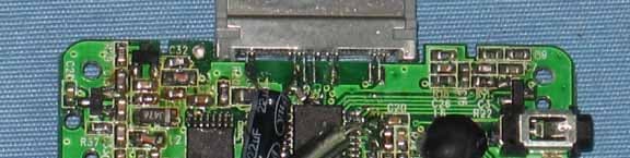
UK3FM915
Jan 20, 2008FM TRANSMITTER
Equipment Class
DXX - Part 15 Low Power Communication Device Transmitter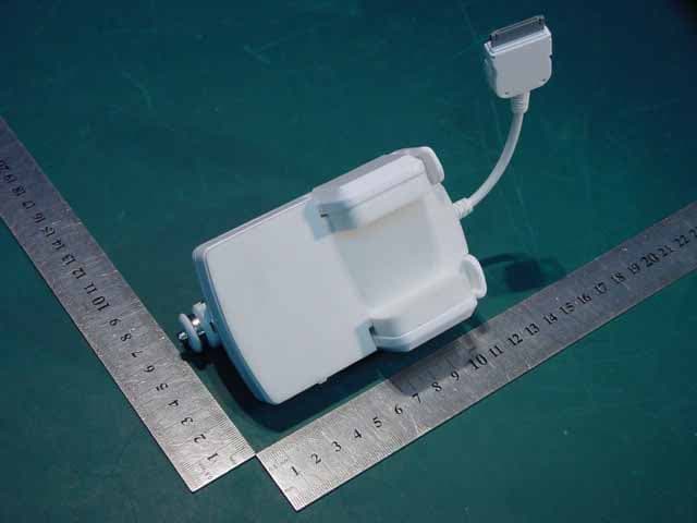
UK3F182
Oct 09, 2006FM Transmitter
Equipment Class
DXX - Part 15 Low Power Communication Device Transmitter