UK3FM915FM TRANSMITTER
Daza Technology Electronics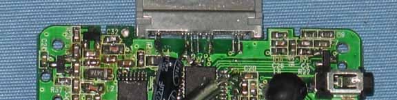
Click to zoom
Application Details
- Equipment Class
- DXX - Part 15 Low Power Communication Device Transmitter
- Date of Grant
- Jan 20, 2008
- Application Purpose
- Original Equipment
- Date of Application
- Jan 20, 2008
- Equipment Note
- FM TRANSMITTER
- Frequency Range
- 88.10000000 - 107.90000000
- Company
- Daza Technology Electronics
- Country
- China
Documents & Files
Document Text
Text extracted from the exhibit documents filed with the FCC. Open a document above to read the original.
Users Manual
4FM915 user manual This is FM transmitter which can comply with the Ipod serial products and it is a good products special for Iphone Function instruction 1. Transmit the music from your Ipod with a frequency for radio. 2. In order to avoid set the frequency every time, the unit will automatic remember the frequency last time used. Manual instruction. 1. The FM transmitter will turn on automaticlly when plug the 30 pin connector to the Ipod jack. 2. Press the button FM transmitter to choose the FM frequency.(To get the best effect, we suggest to use the frequency that are not used by local radio broadcasting station or the frequency with weak signal. 3. Turn on the radio, set the receive frequency same as the fm transmitter then you will listen to the music from Ipod. 4. Plug out the FM transmitter then the unit will turn off automatically. Specifications 1. Frequency stable: ±20PPM(-10°C-+55 )°C 2. Work temperature: -10°C-+55°C 3. Stereo separate: >30dB(1KHz) 4. Audio frequency: 100-15000Hz Repair and Maintenance: 1. Keep the FM transmitter at the place of dry and beyond of Child touch. 2. In case the FM transmitter cant work properly, please check the Ipod power connection ,if the radio turn on or frequency if correct. NOTE: THE MANUFACTURER IS NOT RESPONSIBLE FOR ANY RADIO OR TV INTERFERENCE CAUSED BY UNAUTHORIZED MODIFICATIONS TO THIS EQUIPMENT. SUCH MODIFICATIONS COULD VOID THE USER’S AUTHORITY TO OPERATE THE EQUIPMENT.
Block Diagram
Power manager audio input flitter Key- press bidirectional SIO adapter PLL FM transmit FM stereo modulate MCU ant Ipod iphone Crystal(7.6MHZ)
Cover Letter(s)
1. How does this device operate? Answer: Power is provided by DC 12V power source. Frequencies are scanning by press button on the EUT. Have 199 frequencies: 88.1~107.9 MHz are available. 2. Provide information on the device and its antenna. Answer: The antenna is a built-in trace on the circuit board. (Please see the circuit). 3. How is it installed? Answer: Plug-in connecter is inserted into the DC 12V power source. Install iPod nano into the interface of the EUT for loading audio signal. 4. What test procedure was used? Answer: ANSI C63.4-2003. 5. If tested in a car, how was it configured/tested? Answer: It was not tested in a car. It was tested in a 3-meter test site as shown in the test set-up photograph. 6. Was the tuning range properly verified? The test lab should indicate in the report that the tuning controls were manually adjusted to verify maximum tuning range. Answer: 88.1, 98.0, 107.9 MHz are tested. Please see the test report (Page 10 of 24) and user’s manual. 7. Was the bandwidth properly tested with maximum audio input? The test lab should describe the audio input signal (use a typical audio file from a typical device) - DO NOT use 1kHz tone from signal generator as specified under ETSI EN 301 357-1) Answer: We played a song from iPod nano with the maximum audio input. 8. Does the device operate in a vehicle? Please state that this was verified. Answer: It was not tested in a vehicle.
ID Label/Location Info
FCC ID Label Sample for FCC ID: UK3FM915_ FCC ID: UK3FM915 This device complies with Part 15 of the FCC Rules. Operation is subject to the following two conditions: (1) this device may not cause harmful interference, and (2) this device must accept any interference received, including interference that may cause undesired operation.
Operational Description
Description of principle Power support The transmitter is fed by ipod or iphone power supply Antenna: The transmitter utilize dipole antenna. The power of this signal (Power manager) will be send to MCU. Audio signal will be process by audio input, then it be send to FM stereo modulate. MCU will output pulse to trigger the oscillator and the encoder to generate a carrier frequency and digital code signal when frequency and memory adjustment was pressed. Then the serially digital signal of encoder will mixed with the carrier at modulator stage by was of FSK mode (frequency Modulation) from the RF VCO, this process utilize PLL which compare 19KHZ frequency Modulation signal with signal which is from trigger the oscillator. Then this signal will pass through time frequency to change into the frequency that required. This signal then pass through LC frequency select network and will be sent to transmitter antenna for transmitting. Ground: There is no external ground connection. The ground is only that of the printed circuit board.
Schematics
BW007-FM188B-NEW1.sch-1 - Fri Dec 07 16:19:23 2007
Test Report
Note: This report shall not be reproduced except in full, without the written approval of World standardization Certification &Testing CO.,LTD. This document may be altered or revised by World standardization Certification &Testing CO.,LTD. personnel only, and shall be noted in the revision section of the document. Page 1 Total Page: 24 Rev. 00 FCC CFR 47 PART 15 SUBPART C TEST REPORT Report Number: WSCT07120060E-RF For FM Transmitter Model: 4FM915 Trade Name: N/A Issued to Daza Technology Electronics Room 1410-1411, Block A Jiahe Bldg, Shennan Mid-r Shenzhen Issued by WORLD STANDARDIZATION CERTIFICATION & TESTING CO., LTD. 1-2/F, DACHONG KEJI BUILDING NO.25 OF TONGGU ROAD, NANSHAN DISTRICT, SHENZHEN. PRC TEL: 86-755-26996142 FAX: 86-755-26996253 Page 2 Rev. 00 TABLE OF CONTENTS 1. TEST RESULT CERTIFICATION ............................................................................................. 3 2. EUT DESCRIPTION ..................................................................................................................... 4 3. TEST METHODOLOGY.............................................................................................................. 5 3.1 EUT CONFIGURATION..................................................................................................................... 5 3.2 EUT EXERCISE................................................................................................................................. 5 3.3 GENERAL TEST PROCEDURES.......................................................................................................... 5 3.4 FCC PART 15.205 RESTRICTED BANDS OF OPERATIONS..................................................... 6 3.5 DESCRIPTION OF TEST MODES......................................................................................................... 6 4. INSTRUMENT CALIBRATION ................................................................................................. 7 5. FACILITIES AND ACCREDITATIONS.................................................................................... 8 5.1 FACILITIES...................................................................................................................................... 8 5.2 EQUIPMENT.................................................................................................................................... 8 5.3 LABORATORY ACCREDITATIONS AND LISTINGS............................................................................. 8 6. SETUP OF EQUIPMENT UNDER TEST................................................................................... 9 6.1 SETUP CONFIGURATION OF EUT...................................................................................................... 9 6.2 SUPPORT EQUIPMENT..................................................................................................................... 9 7. FCC PART 15.239 REQUIREMENTS ...................................................................................... 10 7.1 20 DB BANDWIDTH...................................................................................................................... 10 7.2 BAND EDGES MEASUREMENT............................................................................................. 13 7.3 RADIATED EMISSIONS................................................................................................................... 16 7.4 POWERLINE CONDUCTED EMISSIONS............................................................................................ 22 APPENDIX 1 PHOTOGRAPHS OF TEST SETUP....................................................................... 24 Page 4 Rev. 00 2. EUT DESCRIPTION Product FM Transmitter Trade Name N/A Model 4FM915 Power Supply DC12V Operate Frequency 88.1-107.9MHz Modulation Technique FM Number of Channels 199 Channel Remark: The product is a Transmitter. This submittal(s) (test report) is intended for FCC ID: UK3FM915 filing to comply with Section 15.239 of the FCC Part 15 Subpart C Rules. Page 5 Rev. 00 3. TEST METHODOLOGY The tests documented in this report were performed in accordance with ANSI C63.4 and FCC CFR 47 Part 15 Subpart C. 3.1 EUT CONFIGURATION The EUT configuration for testing is installed on RF field strength measurement to meet the Commissions requirement and operating in a manner that intends to maximize its emission characteristics in a continuous normal application. 3.2 EUT EXERCISE The calibrated antennas used to sample the radiated field strength are mounted on a non-conductive, motorized antenna mast 3 meters from the leading edge of the turntable. 3.3 GENERAL TEST PROCEDURES Conducted Emissions The EUT is placed on the turntable, which is 0.8 m above ground plane. According to the requirements in Section 7.1 of ANSI C63.4.Conducted emissions from the EUT measured in the frequency range between 0.15 MHz and 30MHz using CISPR Quasi-Peak detector mode. Radiated Emissions The EUT is a placed on as turntable, which is 0.8 m above ground plane. The turntable shall rotate 360 degrees to determine the position of maximum emission level. EUT is set 3m away from the receiving antenna, which varied from 1m to 4m to find out the highest emission. And also, each emission was to be maximized by changing the polarization of receiving antenna both horizontal and vertical. In order to find out the maximum emissions, exploratory radiated emission measurements were made according to the requirements in Section 13.1.4.1 of ANSI C63.4. Page 6 Rev. 00 3.4 FCC PART 15.205 RESTRICTED BANDS OF OPERATIONS (a) Except as shown in paragraph (d) of this section, only spurious emissions are permitted in any of the frequency bands listed below: MHz MHz MHz GHz 0.090 - 0.110 1 0.495 - 0.505 2.1735 - 2.1905 4.125 - 4.128 4.17725 - 4.17775 4.20725 - 4.20775 6.215 - 6.218 6.26775 - 6.26825 6.31175 - 6.31225 8.291 - 8.294 8.362 - 8.366 8.37625 - 8.38675 8.41425 - 8.41475 12.29 - 12.293 12.51975 - 12.52025 12.57675 - …
Text truncated - open the document above for the full version.
Test Setup Photos
Power Line Conducted Emission Set up Photos Test Mode: Ipod Play
Test Setup Photos
Page 23 Rev. 00 APPENDIX 1 PHOTOGRAPHS OF TEST SETUP Radiated Emission Set up Photos Test Mode: IPod Play
Contact Information
Applicant
Longbiao Lei(Manager)
Test Firm
World Standardization Certification&Testing CO.,LTSuxia Zhou
Technical Specifications
| # | Rule Parts | Frequency Range | Power Output |
|---|---|---|---|
| 1 | 15C | 88.1 MHz - 107.9 MHz | - |
Other Applications from Daza Technology Electronics

UK3-F172
Dec 15, 2009FM Transmitter
Equipment Class
DXX - Part 15 Low Power Communication Device TransmitterUK3MP1073
May 16, 2007FM TRANSMITTER
Equipment Class
DXX - Part 15 Low Power Communication Device Transmitter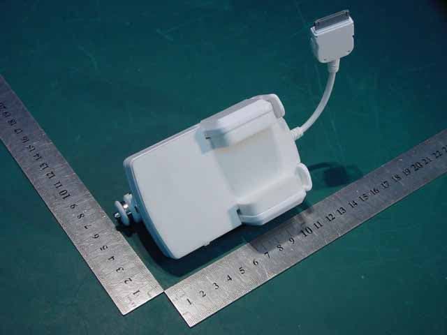
UK3F182
Oct 09, 2006FM Transmitter
Equipment Class
DXX - Part 15 Low Power Communication Device Transmitter