UK4JTCM1000Vehicle driving logs tracker
Jastec Co., Ltd.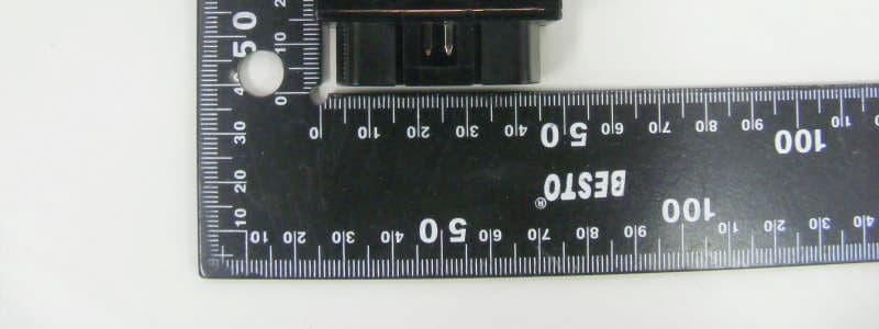
Click to zoom
Application Details
- Equipment Class
- PCB - PCS Licensed Transmitter
- Date of Grant
- Jan 27, 2013
- Application Purpose
- Original Equipment
- Date of Application
- Jan 27, 2013
- Equipment Note
- Vehicle driving logs tracker
- Frequency Range
- 1851.25000000 - 1908.75000000
- Company
- Jastec Co., Ltd.
- Country
- South Korea
Documents & Files
Document Text
Text extracted from the exhibit documents filed with the FCC. Open a document above to read the original.
Users Manual
von-S2 Manual Instruction von-S2 Information This confidential information is not supposed to disclosed and misused to the third party 1 •Certified Business Name: Jastec Co.,Ltd. •Device (model): Vehicle Fleet Management Service System •Manufacture date: Jan, 2013 •Manufacturer/country : Jastec Co,Ltd./Korea •Certified code : JS0 •A radio interference of this wireless module is not providing a service related the safety of life. This confidential information is not supposed to disclosed and misused to the third party 2 We kindly recommend you to be fully aware of using a product accurately and for safety of user. All liabilities by uncomplying cautions are not supposed to be responsible to manufacturer. 1. This product into water or prolonged exposure to moisture can cause failure resulting in no charge for broken A/S. 2. Do not disassemble or repair this product if the label seal is broken or damaged, free A/S will not be received. 3. Do not separate or equip von-F module while driving vehicle or ignition off. – This causes to car accident and defective of it. 4. Please note that on the surface of the product carefully to avoid strong detergent or chemicals. 5. This product works under the proper temperature -30~+70°C. 6. Do not impact the product. It’s the cause of product defective. 7. Using other products rated voltage is the cause of the crush. Rated voltage state must be sure to use the product. 8. After parking vehicle in a safe place, install von-F module then drive. 9. When installing or removing product on the vehicle as the vehicle peripheral device could be due to injury, Please be careful. 10. Incorrect installation of the product by the vehicle’s shock and vibration and can cause data loss, after the installation, please check it properly. 11. Products by shock or vibration of the vehicle is released from the car because it can cause data loss if the installation status checks on a regular basis. This product is equipped with a breakdown of the car by the impact of accidents, damage, of driving record, we are not responsible for missing. Cautions For Safety 1. von-S2 Descriptions This confidential information is not supposed to disclosed and misused to the third party 3 1.1 Overview von-S2 as vehicle Fleet Management Service System designed to collect a vehicle driving information from ECU(Electronic Control Unit) By OBD standard protocol communication and can be saved a driving logs by connecting to PC. Von-S2 GPS This confidential information is not supposed to disclosed and misused to the third party 4 1.2 Specifications 1. von-S2 Descriptions Item Description CPU Processor External Memory In-Vehicle Protocol Status Supported Functions Vehicle Interface USB Port CDMA or GSM/GPRS G-Sensor GPS MIC Function Internal Battery Operational Voltage Power Consumption Dimensions Weight Operating Temperature Storage Temperature 32-bit ARM Cortex-M3(256KB Flash, 64KB SRAM) 4MB Serial Flash Memory ISO 9141-2, ISO 14230-4(KWP-2000), ISO 15765-4(CAN), SAE J1850(PWM/VPWM) 2-LEDs (Power, CDMA) SAE J1979 Mode $01~$0A SAE J1962 Standard OBD-II 16 PIN Connector USB 2.0 Compatible, VCP(Vitural COM Port) Supported 800/1900 MHz 1xRTT, GSM/GPRS/EDGE 850/900/1800/1900MHz Bosch 3-Axis 10-Bit Resolution, BMA150 SGPS, AGPS, gpsOneXTRA-tm Microphone (Emergency Call) 500mAh DC 8V ~16V or USB 5V Support TBD Max. 46mm(W) x 25mm(D) x 66mm(H) 54g -30 ~ 70°C -55 ~ 100°C This confidential information is not supposed to disclosed and misused to the third party 5 1.3 Functions Driving logs record Saving vehicle information. Collecting and saving driving logs information. Vehicle identification information / module certification / module serial number information / driving data starting time and ending time / ignition On and Off time / Accumulated driving distance / module connection and disconnection time / driving information transmitting time / acceleration pedal or throttle valve open angle Driving information security Encoded saving data to not modify a driving recorded information. Driving information upload CDMA 1x transmitter preferred. Power saving function Automatically power will be off when ignition off. Self diagnostic Supporting self diagnostic function through von-F module operating check (Indicator). Firmware upgrade support Supporting firmware upgrade 1. von-S2 Descriptions This confidential information is not supposed to disclosed and misused to the third party 6 1.4 Composition Name Function von-S2 module Connection to vehicle OBD diagnostic port. USB cable Firmware Update Quick Start Manual Quick guide manual Program installation CD von-S2 PC Manager installation program 1. von-S2 Descriptions This confidential information is not supposed to disclosed and misused to the third party 7 1.5 Body description display LED 2-Indicator display LED DLC connector Connect to vehicle OBD diagnostic port. USB Connector F/W Update Connector 1. von-S2 Descriptions This confidential information is not supposed to disclosed and misused to the third party 8 2.1 von-S2 module installation von-S2 module installation is following below order. 1.von-F module installation requires after vehicle parking in safety area. ** Caution : A side brake or foot brake should be locked and shift also checked on the parking position. 2.Please check vehicle engine should be off when if ignition on 2. Product Instructions This confidential information is not supposed to disclosed and misused to the third party 9 2.3 von-S2 module separation ** Caution : von-F module separation should be performed at safety area after parking. ** Caution : The separation from vehicle is prohibited if not the purpose of driving data saving or transmitting. ** Caution : Performing von-F module separation on ignition on may be caused to data loss or module damaged. 1.Turn vehicle ignition off. 2.Pull von-F module from vehicle OBD diagnostic Cable then separating it. 2. Product Instructions This confidential information is not supposed to disclosed…
Text truncated - open the document above for the full version.
Cover Letter(s)
Date: December 18, 2012 Federal Communications Commission 7435 Oakland Mills Road Columbia MD 21046 c.c. Compliance Certification Services Certification Division 47173 Benicia Street Fremont, CA 94538, USA To whomit may concern: I, the undersigned, hereby authorize Lab Manager Charles. Kim (or Feel. Jeong) and of SGS Korea Co., Ltdand hereafter referred to as SGS Korea, to act on our behalf in all manners relating to application for equipment authorization, including signing of all documents relating to these matters. Any and all acts carried out by Lab Manager Charles. Kim (or Feel. Jeong) of SGS Korea Co., Ltdon our behalf shall have the same effect as acts of our own. I, the undersigned, hereby certify that we are not subject to a denial of federal benefits, that includes FCC benefits, pursuant to Section 5301 of the Anti-Drug Abuse Act of 1988, 21 U.S.C. 853(a). In authorizing SGS Korea as our agent, we still recognize that we are responsible to: a)comply with the relevant provisions of the certification program; b)make all necessary arrangements for the conduct of the evaluation, including provision for examining documentation and access to all areas, records (including internal audit reports) and personnel for the purposes of evaluation (e.g. testing, inspection, assessment, surveillance, reassessment) and resolution of complaints; c)make claims regarding certification only in respect of the scope for which certification has been granted; d)do not use our product certification in such a manner as to bring the Certification Division into disrepute andnot make any statement regarding our product certification which the Certification Division may consider misleading or unauthorized; e)upon suspension or cancellation of certification, discontinue use of all advertising matter that contains any reference thereto and return any certification documents as required by the Certification Division; f)use certification only to indicate the products are certified as being in conformity with specified standards; g)endeavor to ensure that no certificate or report nor any part thereof is used in a misleading manner; h)ensure that any reference to our product certification in communication media such as documents, brochures or advertising, complies with the requirements of the Certification Division; i)keep a record of all complaints made known to the us relating to the product’s compliance with requirements of the relevant standard and to make these records available to the Certification Division when requested; j)take appropriate action with respect to such complaints and any deficiencies found in products or services that affect compliance with the requirements for certification; k)document the actions taken. This authorization is valid until further written notice from the applicant. Sincerely Yours, Manager Jastec Co., Ltd.
Cover Letter(s)
Jastec Co., Ltd. Jastec B/D, 92-7, Kumgok-Dong, Boondang-Gu, Seongnam-Si, Kyunggi-Do Federal Communications Commission 7435 Oakland Mills Road Columbia, MD 21046 Gentlemen: This letter is to comply with Section 0.457(d)(2)(i) and 0.459 pertaining to confidential material. We, Jastec Co., Ltd.would like the following documents regarding this submission for FCC ID: We are also hereby request ShortTerm Confidentiality for 180 days after the grant as outlined in Public Notice DA 041705. This provision will give Jastec Co., Ltd temporary confidentiality of commercially sensitive information prior to product release. The requested Permanent and Temporary Confidential exhibits are listed as follows: UK4JTCM1000to be kept confidential. 1 Block Diagram 2 Operational Descriptions Permanent 3 Schematics 7 External Photos 8 Internal Photos 9 Test-Setup Photos Short-Term 10 User’s Manual The above material contains trade secrets or technical data, which would customarily be guarded fromcompetitors.We do not want these documents to be accessible to the general public. Sincerely, 4 Installation Instructions 5 Antenna Information 6 Tuneup Procedure Manager Jastec Co., Ltd. Confidential List
External Photos
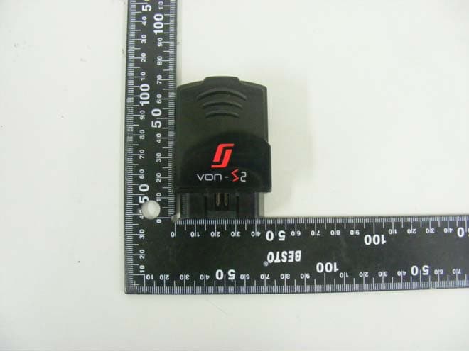
External photos of EUT Front view of EUT Rear view of EUT Top view of EUT Bottom view of EUT Side view of EUT
ID Label/Location Info
FCC Label 1.FCC Label Drawing 2.FCC Label Location JastecCo.,Ltd. Model: JTCM1000 FCC ID: UK4JTCM1000 Madein Korea Bottom side of EUT
Internal Photos
Internal photos of EUT Inner of EUT Antenna of EUT Antenna Top view of PCB1 Bottom view of PCB1 Top view of PCB2 Bottom view of PCB2 Top view of PCB3 Bottom view of PCB3 Top view of Module PCB Bottom view of Module PCB
RF Exposure Info
FCC ID : UK4JTCM1000 According to KDB 447498 D01 General RF Exposure Guidance v05, section 4.3.1 At 100㎒to 6㎓and fortest separation distances> 50 mm, the SAR test exclusion threshold is determined according to the following; a) [(Threshold at 50 mm in step 1) + (test separation distance – 50 mm) x (f (㎒) / 150)]㎽, 100 ㎒ to 1500 ㎒ b) [(Threshold at 50 mm in step 1) + (test separation distance – 50 mm) x 10]㎽ at > 1500㎒ and ≤ 6 ㎓ 1. SAR test exclusion threshold Cellular Band : 824.70㎒ (min. separation distances = 110 mm) Threshold at 50 mm in step 1 = 150 /√0.0.82470 = 165.17㎽ SAR test exclusion thresholds(110 mm) = 165.17 + 60 x (824.70 / 150) = 495.05㎽ Max. conducted power(㎽) SAR Test Exclusion Thresholds(110 mm) (㎽) 340.41495.05 PCS Band : 1 880.00㎒ (min. separation distances = 110 mm) Threshold at 50 mm in step 1 = 150 / √1.880 = 109.40 ㎽ SAR test exclusion thresholds(110 mm) = 109.40 + 60 x 10 = 709.40㎽ Max. conducted power(㎽) SAR Test Exclusion Thresholds(110 mm) (㎽) 317.69709.40 2. Conclusion : No SAR is required.
Test Report
Report Number:F690501/RF-RTL006067-1Page:2of39 The results shown in this test report refer only to the sample(s) tested unless otherwise stated. This test report cannot be reproduced, except in full, without prior written permission of the Company. SGSKoreaCo.,Ltd.(GunpoLaboratory)18-34, Sanbon-dong, Gunpo-si, Gyeonggi-do, Korea, 435-040 Tel. +82 31 428 5700 / Fax. +82 31 427 2371www.ee.sgs.com/korea INDEX TABLE OF CONTENTSPage 1. General Information --------------------------------------------------------------------------------------3 2. RF radiated output power & spurious radiated emission ---------------------------------------7 3. Conducted Output Power -------------------------------------------------------------------------------13 4. Occupied Bandwidth 99 % ------------------------------------------------------------------------------16 5. Peak-Average Ratio --------------------------------------------------------------------------------------22 6. Spurious Emissions At Antenna Terminal-----------------------------------------------------------25 7. Band Edge --------------------------------------------------------------------------------------------------32 8. Frequency Stability ---------------------------------------------------------------------------------------37 Report Number:F690501/RF-RTL006067-1Page:3of39 The results shown in this test report refer only to the sample(s) tested unless otherwise stated. This test report cannot be reproduced, except in full, without prior written permission of the Company. SGSKoreaCo.,Ltd.(GunpoLaboratory)18-34, Sanbon-dong, Gunpo-si, Gyeonggi-do, Korea, 435-040 Tel. +82 31 428 5700 / Fax. +82 31 427 2371www.ee.sgs.com/korea 1. General information 1.1. Testing laboratory SGS Korea Co., Ltd. (Gunpo Laboratory) -Wireless Div. 3FL, 18-34, Sanbon-dong, Gunpo-si, Gyeonggi-do, Korea 435-040 All SGS services are rendered in accordance with the applicable SGS conditions of service available on request and accessible athttp://www.sgs.com/en/Terms-and-Conditions.aspx. Telephone:+82 31 428 5700 FAX:+82 31 427 2371 1.2. Details of applicant Applicant:JASTEC CO., LTD. Address:92-7 Kumgok-dong, Boondang-gu, Seongnam-si, Gyeonggi-do, Korea Contact Person:Park, Chul-Hong Phone No.:+82 70 7606 1694 Fax No.:+82 31 716 0379 1.3. Description of EUT Kind of Product Vehicle driving logs tracker Model Name JTCM-1000 Serial Number N/A Power Supply DC 12 V (power source used on vehicle) Rated Power CDMA800: 23㏈m CDMA1900: 23㏈m Frequency Range CDMA800: 824.70㎒~ 848.31㎒ CDMA1900: 1 851.25㎒~ 1 908.75㎒ Antenna Gain CDMA800: 1.92㏈i CDMA1900: 1.85㏈i Support Mode 1xRTT Emission Designator CDMA800 (1xRTT): 1M29F9W CDMA1900 (1xRTT): 1M29F9W H/W Version v0.3 S/W Version v0.01 Report Number:F690501/RF-RTL006067-1Page:4of39 The results shown in this test report refer only to the sample(s) tested unless otherwise stated. This test report cannot be reproduced, except in full, without prior written permission of the Company. SGSKoreaCo.,Ltd.(GunpoLaboratory)18-34, Sanbon-dong, Gunpo-si, Gyeonggi-do, Korea, 435-040 Tel. +82 31 428 5700 / Fax. +82 31 427 2371www.ee.sgs.com/korea 1.4. Maximum output power The transmitter has a maximum ERP & EIRP and Average output power as follows: -Cellular Band Frequency Range (㎒) ModulationChannel Average Output PowerE.R.P. ㏈m㎽㏈m㎽ 824.70 1xRTT RC3 55 (Loopback) 1 01325.32340.4126.94494.31 836.5238424.61289.0725.43349.14 848.3177724.18261.8226.14411.15 -PCS Band Frequency Range (㎒) ModulationChannel Average Output PowerE.I.R.P. ㏈m㎽㏈m㎽ 1 851.25 1xRTT RC5 55 (Loopback) 2524.98314.7725.03318.42 1 880.0060025.02317.6923.21209.41 1 908.751 17524.42276.6924.78300.61 1.5. Worst case configuration -Test mode CDMA (800 / 1900) We found out the test mode with the highest power level in the section of output power after we investigated average output power of all the modulations and (or) data rates for each mode. So we chose below test mode as a representative of worst case. - CDMA 1xRTT 1.6. Sample calculation for offset Where relevant, the following sample calculation is provided: 1.6.1. Conducted test Offset value (㏈) = Directional Coupler (㏈) + Attenuator (㏈) + Cable loss (㏈) 1.6.2. Radiation test E.R.P. & E.I.R.P = [S.G level + Amp.](㏈m) - Cable loss(㏈) + Ant. gain (㏈d/㏈i) Report Number:F690501/RF-RTL006067-1Page:5of39 The results shown in this test report refer only to the sample(s) tested unless otherwise stated. This test report cannot be reproduced, except in full, without prior written permission of the Company. SGSKoreaCo.,Ltd.(GunpoLaboratory)18-34, Sanbon-dong, Gunpo-si, Gyeonggi-do, Korea, 435-040 Tel. +82 31 428 5700 / Fax. +82 31 427 2371www.ee.sgs.com/korea 1.7. Test equipment list EquipmentManufacturerModelS/NCal. Date Cal. Interval Cal. Due. Signal GeneratorR&S SMBV100A255834 Jul, 02. 2012AnnualJul, 02. 2013 Signal GeneratorR&S SMR40100272 Aug. 23, 2012AnnualAug. 23, 2013 Spectrum AnalyzerAgilent E4440AMY43362142 Mar. 29, 2012AnnualMar. 29, 2013 Spectrum AnalyzerR&SFSV30100768Mar. 29, 2012AnnualMar. 29, 2013 Mobile Test UnitAgilent E5515CGB43345198 Mar. 29, 2012AnnualMar. 29, 2013 AttenuatorAgilent8495BMY42140907Mar. 31, 2012 Annual Mar. 31, 2013 AttenuatorMini-CircuitsBW-N20W5+9050-1Mar. 30, 2012 Annual Mar. 30, 2013 Low Pass FilterMini-Circuits NLP-1200+ V8979400903-1Jul. 12, 2012 Annual Jul. 12, 2013 High Pass FilterWainwrightWHK3.0/18G-10SS344 Jul. 12, 2012AnnualJul. 12, 2013 High Pass FilterWainwrightWHKX1.5/15G-6SS4 Mar. 30, 2012AnnualMar. 30, 2013 DC Power SupplyAgilentU8002AMY50020026Mar. 29, 2012 Annual Mar. 29, 2013 PreamplifierH.P.8447F2944A03909Jul. 03, 2012AnnualJul. 03, 2013 PreamplifierR&SSCU 1810117Jan. 02, 2012 Annual Jan. 02, 2013 PreamplifierMITEQ Inc.JS44-18004000-35-8P1546891Jul. 12, 2012 Annual Jul. 12, 2013 Test ReceiverR&SESU26100109Feb. 21, 2012 Annual Feb. 21, 2013 Bilog Antenna SCHWARZBECK MESSELEKTRONIK VULB9163396May 12, 2011BiennialMay 12, 2013 Horn AntennaR&SHF906 100326Nov. 23, 2011BiennialNov. 23, 2013 Hor…
Text truncated - open the document above for the full version.
Test Setup Photos
Test setup photo of EUT A. Photo of Fundamental & Spurious Emission Test
Contact Information
Applicant
Park Cheol-Hong(Manager)
Test Firm
SGS Korea Co., Ltd.Forest Lee
Technical Specifications
| # | Rule Parts | Frequency Range | Power Output | Emission | Tolerance |
|---|---|---|---|---|---|
| 2 | 24E | 1.85 GHz - 1.91 GHz | 318.00 mW | 1M29F9W | 2.5 ppm |
Other Applications from Jastec Co., Ltd.
UK4JTGM-1100
Jun 17, 2013Vehicle Fleet Management Service System
Equipment Class
PCB - PCS Licensed Transmitter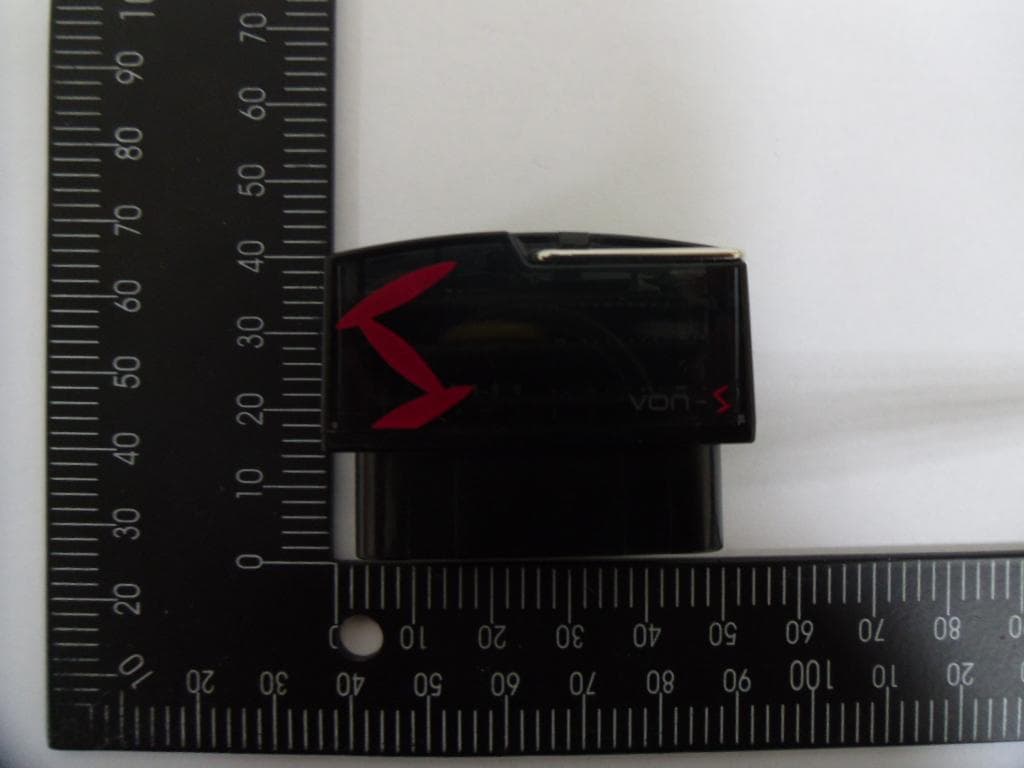
UK4JTBT2200
Jan 29, 2013Vehicle driving logs tracker
Equipment Class
DSS - Part 15 Spread Spectrum Transmitter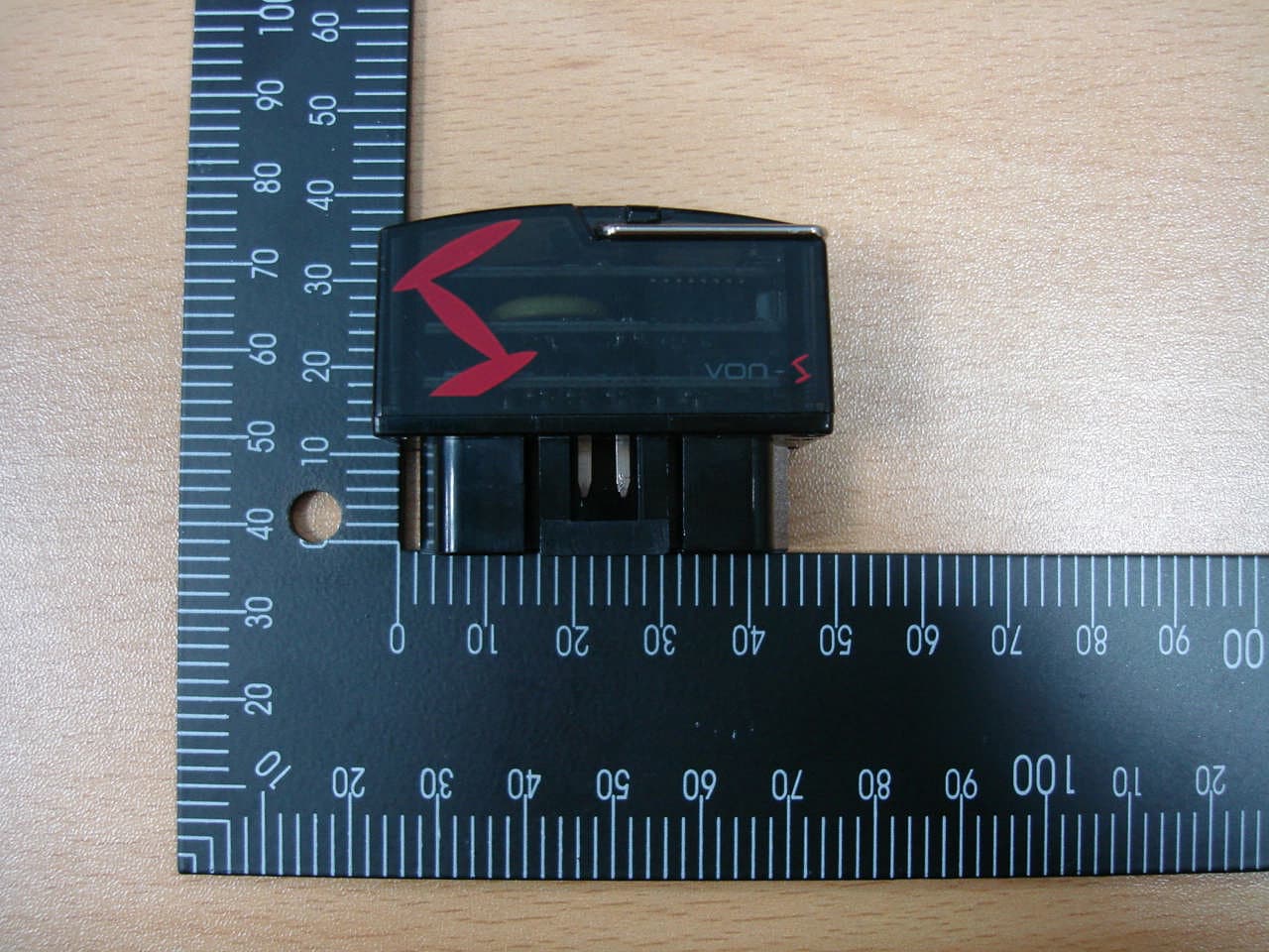
UK4JTBT2100
Oct 18, 2011Vehicle driving logs tracker
Equipment Class
DSS - Part 15 Spread Spectrum Transmitter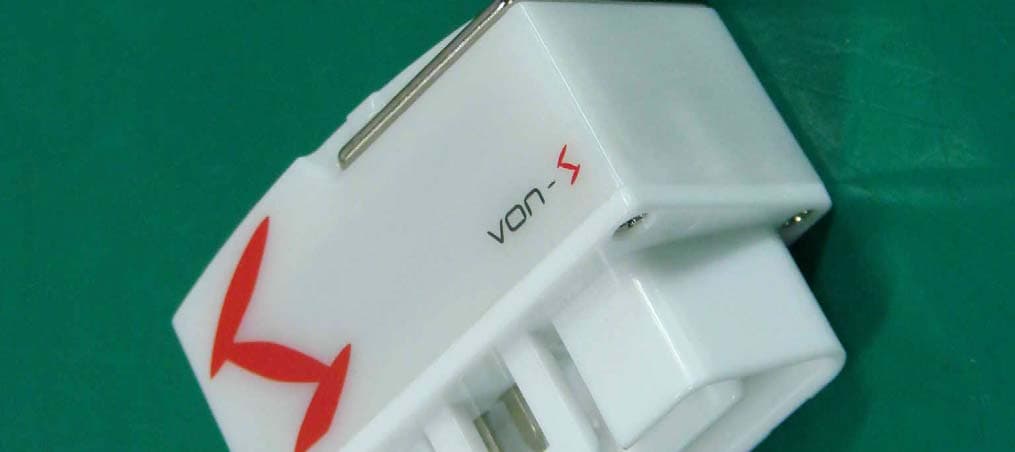
UK4JTWF1100
Aug 23, 2011von-STD
Equipment Class
DTS - Digital Transmission System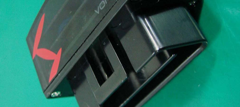
UK4JTBT1100
Aug 22, 2011von-STD
Equipment Class
DSS - Part 15 Spread Spectrum Transmitter