ULE2564-130IntelliFire Touch Technology -Electronic Control Module(IFT-ECM)
Hearth & Home Technologies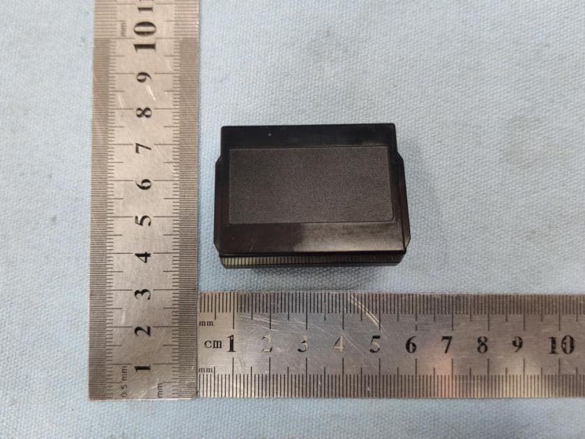
Click to zoom
Application Details
- Equipment Class
- DXX - Part 15 Low Power Communication Device Transmitter
- Date of Grant
- Nov 15, 2020
- Application Purpose
- Original Equipment
- Date of Application
- Nov 15, 2020
- Equipment Note
- IntelliFire Touch Technology -Electronic Control Module(IFT-ECM)
- Frequency Range
- 912.20000000 - 918.00000000
- Company
- Hearth & Home Technologies
- Country
- United States
Documents & Files
Document Text
Text extracted from the exhibit documents filed with the FCC. Open a document above to read the original.
Users Manual
1 Heat & Glo • PRIMO48, PRIMO48ST, PRIMO60, PRIMO60ST, PRIMO72, PRIMO72ST Owner’s Manual • 9/20 Owner’s Manual Care and Operation NOTICE: DO NOT discard this manual! In the Commonwealth of Massachusetts installation must be performed by a licensed plumber or gas fi tter. See appliance Installation Manual for additional Commonwealth of Massachusetts requirements. INSTALLER: Leave this manual with party responsible for use and operation. OWNER: Retain this manual for future reference. Contact your dealer with questions regarding installation, operation or service. This appliance may be installed as an OEM installation in manufactured home (USA only) or mobile home and must be installed in accordance with the manufacturer’s instructions and the Manufactured Home Construction and Safety Standard, Title 24 CFR, Part 3280 in the United States, or the Standard for Installation in Mobile Homes, CAN/CSA Z240 MH Series, in Canada. This appliance is only for use with the type(s) of gas indicated on the rating plate. This appliance is not convertible for use with other gases, unless a certifi ed kit is used. DANGER HOT GLASS WILL CAUSE BURNS. DO NOT TOUCH GLASS UNTIL COOLED. NEVER ALLOW CHILDREN TO TOUCH GLASS. A (glass) barrier designed to reduce the risk of burns from the hot viewing glass is provided with this appliance and shall be installed for the protection of children and other at-risk individuals. • DO NOT store or use gasoline or other fl am- mable vapors and liquids in the vicinity of this or any other appliance. • What to do if you smell gas - DO NOT try to light any appliance. - DO NOT touch any electrical switch. DO NOT use any phone in your building. - Leave the building immediately. - Immediately call your gas supplier from a neighbor’s phone. Follow the gas sup- plier’s instructions. - If you cannot reach your gas supplier, call the fi re department. • Installation and service must be performed by a qualifi ed installer, service agency, or the gas supplier. WARNING: FIRE OR EXPLOSION HAZARD Failure to follow safety warnings exactly could result in serious injury, death, or property damage. This appliance comes standard with patented SafeSurface TM Glass which keeps the surface temperature of the barrier glass at a safe level and will still be hot to the touch when operated for long periods of time. SafeSurface TM Glass complies with the barrier requirements of ANSI Z21.50-2016 CSA 2.22-2016 for vented gas fi replaces.If the barrier glass is removed, the inner glass temperature will be very hot and cause burns. Models: Pour demander un exemplaire en français de ce Manuel du propriétaire, visitez www.heatnglo.com/translations. PRIMO48ST PRIMO60ST PRIMO72ST PRIMO48 PRIMO60 PRIMO72 These gas appliance models are built with the following electronic control module which is in compliance with Federal Communications Commission (FCC) and Industry Standard of Canada (IC). Model Name: IntelliFire Touch Technology - Electronic Control Module (IFT-ECM) Model No: 2564-130 Heat & Glo • PRIMO48, PRIMO48ST, PRIMO60, PRIMO60ST, PRIMO72, PRIMO72ST Owner’s Manual • 9/20 2 Listing Label Information/Location A. Congratulations Congratulations on selecting a Heat & Glo gas fi replace, an elegant and clean alternative to wood burning fi replaces. The Heat & Glo gas fi replace you have selected is designed to provide the utmost in safety, reliability, and effi ciency. As the owner of a new fi replace, you’ll want to read and carefully follow all of the instructions contained in this owner’s manual. Pay special attention to all cautions and warnings. This owner’s manual should be retained for future reference. We suggest that you keep it with your other important documents and product manuals. The information contained in this owner’s manual, unless noted otherwise, applies to all models and gas control systems. Your new Heat & Glo gas fi replace will give you years of durable use and trouble-free enjoyment. Welcome to the Heat & Glo family of fi replace products! Gas and Electric Information Serial Number Type of Gas The model information regarding your specifi c fi replace can be found on the rating plate usually located in the control area of the fi replace. Model Number Not Not for for use use with with solid solid fuel.fuel. ((Ne Ne doit doit pas pas entre entre utilise utilise avec avec un un combustible combustible solide).solide). This This appliance appliance must must be be installed installed in in accordance accordance with with local local codes, codes, if if any; any; if if not, not, follow follow ANSI ANSI Z223.1Z223.1 in in the the USA USA or or CAN/CGA CAN/CGA B149 B149 installation installation codes. codes. (Installer (Installer l’appareil l’appareil selon selon les les codes codes ou ou reglementsreglements locaux locaux ou, ou, en en l’absence l’absence de de tels tels reglements, reglements, selon selon les les codes codes d’installation d’installation CAN/CGA-B149.)CAN/CGA-B149.) Type Type of of Gas Gas (Sorte (Sorte De De Gaz)Gaz):: NNAATURALTURAL GASGAS MADE MADE IN IN USAUSA Minimum Minimum Permissible Permissible Gas Gas Supply Supply for for Purposes Purposes of of Input Input Adjustment.Adjustment. Approved Approved Minimum Minimum (De (De Gaz) Gaz) AcceptableAcceptable 0.00.0 in in w.c.w.c.(Po. (Po. Col. Col. d’eau)d’eau) Maximum Maximum Pressure Pressure (Pression)(Pression) 0.00.0 in in w.c.w.c.(Po. (Po. Col. Col. d’eau)d’eau) Maximum Maximum Manifold Manifold Pressure Pressure (Pression)(Pression) 0.00.0 in in w.c.w.c.(Po. (Po. Col. Col. d’eau)d’eau) Minimum Minimum Manifold Manifold Pressure Pressure (Pression)(Pression) 0.00.0 in in w.c.w.c.(Po. (Po. Col. Col. d’eau)d’eau) Model:Model: (Modele):(Modele): SerialSerial (Serie):(Serie): ANSI ANSI Z21XX-XXXX Z21XX-XXXX · · CSA CSA 2.XX-MXX 2.XX-MXX XXXXXXXXXXXXXXXX IN IN CANADACANADA ALTITUDE:ALTITUDE:0-0000 0-0000 FT.FT.0000-0000FT.0000-0000FT. MAX. MAX. INPUT INPUT BTUH:BTUH:00,00000,00000,00000,000 MIN. MIN. INPUT INPUT BTUH…
Text truncated - open the document above for the full version.
Users Manual
Heat & Glo • PRIMO48, PRIMO48ST, PRIMO60, PRIMO60ST, PRIMO72, PRIMO72ST Owner’s Manual • 9/20 20 Figure 4.3 Replace Barrier Glass - Clean Face Finish BARRIER GLASS TABS THIS SIDE OUT NOTE: INSTALL BARRIER GLASS PRINTED SIDE OUT.“THIS SIDE OUT” MUST BE LEGIBLE ON BARRIER GLASS. VERTICAL GAP REQUIRED 21 Heat & Glo • PRIMO48, PRIMO48ST, PRIMO60, PRIMO60ST, PRIMO72, PRIMO72ST Owner’s Manual • 9/20 Removing Firebox Glass Assembly 1. Remove the transition media from the appliance. Lift the transition media tray out of appliance. Disconnect the wires that are connected to the reset switch. The transition media tray fi ts tightly, lift carefully. See Fig- ure 4.4. 2. Locate the glass clips that are on the upper edge of the glass frame of the appliance. See Figure 4.4. 3. Use both index fi ngers to release the glass clips. 4. Allow glass to tilt forward. Lift up and out. The glass will lift out of the bottom retaining lip. Replacing Firebox Glass Assembly 1. Locate retaining lip on lower front face of fi rebox. Note: Remove any media that may have fallen into the glass retaining lip. 2. Place glass assembly into retaining lip. Tilt top of glass assembly toward fi replace. 3. Assure proper left to right placement of glass and en- gage all four spring latches. Figure 4.4 Location of Glass Clips and Transition Media Tray GLASS CLIPS TRANSITION MEDIA TRAY TRANSITION MEDIA TRAY ROCK LEDGE Firebox Gasket Seal and Firebox Glass Assembly Inspection Frequency: Annually By: Qualifi ed Service Technician Tools needed: Protective gloves, suction cups, drop cloth and a stable work surface. • Inspect condition of gasket seal. • Inspect fi rebox glass for scratches and nicks that can lead to breakage when exposed to heat. • Confi rm there is no damage to glass or glass frame. Replace as necessary. • Verify that firebox glass is properly retained and attachment components are intact and not damaged. Replace as necessary. Firebox Frequency: Annually By: Qualifi ed Service Technician Tools needed: Protective gloves, sandpaper, steel wool, cloths, mineral spirits, primer and touch-up paint. • Inspect for paint condition, warped surfaces, corrosion or perforation. Sand and repaint as necessary. • Replace fi replace if fi rebox has been perforated. Control Compartment and Firebox Top Frequency: Annually By: Qualifi ed Service Technician Tools needed: Protective gloves, vacuum cleaner, dust cloths • Vacuum and wipe out dust, cobwebs, debris or pet hair. Use caution when cleaning these areas. Screw tips that have penetrated the sheet metal are sharp and should be avoided. • Remove all foreign objects. • Verify unobstructed air circulation. Heat & Glo • PRIMO48, PRIMO48ST, PRIMO60, PRIMO60ST, PRIMO72, PRIMO72ST Owner’s Manual • 9/20 22 Burner Ignition and Operation Frequency: Annually By: Qualifi ed Service Technician Tools needed: Protective gloves, vacuum cleaner, whisk broom, fl ashlight, voltmeter, indexed drill bit set, and a manometer. • Verify burner is properly secured and aligned with pilot or igniter. • Clean off burner tube, inspect for plugged ports, corrosion or deterioration. Replace burner if necessary. • Inspect for lifting or other fl ame problems. • Verify air shutter setting is correct. See Installation Manual for required air shutter setting. Verify air shutter is clear of dust and debris. • Inspect orifi ce for soot, dirt and corrosion. Verify orifi ce size is correct. See Service Parts List for proper orifi ce sizing. • Verify manifold and inlet pressures. Adjust regulator as required. • Check all accessible gas-carrying tubes, connections, pipes and other components for leaks. • Inspect pilot fl ame pattern and strength. See Figure 45for proper pilot fl ame pattern. Clean or replace orifi ce spud as necessary. • Inspect IntelliFire Plus flame sensing rod for soot, corrosion and deterioration. Polish with fi ne steel wool or replace as required. • Verify IntelliFire Plus micro-amp output. Replace as necessary. • Verify that there is not a short in fl ame sense circuit by checking continuity between pilot hood and fl ame sensing rod. Replace pilot as necessary. • Check for smooth lighting and ignition carryover to all ports. Verify that there is no ignition delay. Inspect and ensure the lighting of the main burner occurs within four seconds of the main gas valve opening. Figure 4.5 IPI Pilot Flame Pattern 23 Heat & Glo • PRIMO48, PRIMO48ST, PRIMO60, PRIMO60ST, PRIMO72, PRIMO72ST Owner’s Manual • 9/20 5 5 Frequently Asked Questions and Troubleshooting A. Frequently Asked Questions ISSUESOLUTIONS Appliance shuts down without command from remote control. This model is equipped with a safety limit switch that force shutdown of the appliance if tempera- ture exceeds specifi cations. Verify that power vent and optional PowerFlow™ Heat Management system(s) are functioning correctly. The appliance has a safety feature that automatically shuts down the fi replace after nine hours of continuous operation without receiving a command from the remote. Condensation on the glass This is a result of gas combustion and temperature variations. As the fi replace warms, this con- densation will disappear. Blue fl ames This is a result of normal operation and the fl ames will begin to yellow as the fi replace is allowed to burn for 20 to 30 minutes. Odor from fi replace When fi rst operated, this fi replace may release an odor for the fi rst several hours. This is caused by the curing of materials from manufacturing. Odor may also be released from fi nishing materi- als and adhesives used near the fi replace. These circumstances may require additional curing related to the installation environment. Flame appears colorless Burner glass is installed incorrectly or media pieces may be lodged between burner glass and burner tube. Film on the glass This is a normal result of the curing process of the paint. Glass should be cleaned within 3 to 4 hours of initial burning. A non-abrasive cleaner such as gas appliance glass clea…
Text truncated - open the document above for the full version.
Cover Letter(s)
Hearth & Home Technologies Agent Authorization Company: Hearth & Home Technologies Address: 800 W. Jefferson Street, Lake, Minnesota 55041, United States Product Name: IntelliFire Touch Technology -Electronic Control Module(IFT-ECM) Model Number(s): 2564-130 Product Description: IntelliFire Touch Technology -Electronic Control Module(IFT- ECM) We authorize MiCOM Labs Inc., 575 Boulder Court, Pleasanton, California 94566, USA, to act on our behalf on all matters concerning the certification of above named equipment. We declare that MiCOM Labs Inc. is allowed to forward all information related to the approval and certification of equipment to the regulatory agencies as required and to discuss any issues concerning the approval application. Any and all acts carried out by MiCOM Labs on our behalf shall have the same effect as acts of our own. Signature: Date: 2020-06-12 Name: Davd C Lyons Title: VP R & D HHT Company: Hearth & Home Technologies
Cover Letter(s)
< Hearth & Home Technologies > Office of Engineering Technology Federal Communications Commission 7435 Oakland Mills Road Columbia, MD21046 Date: 2020-06-12 Subject; Request for Long Term Confidentiality FCC ID: ULE2564-130 To Whom It May Concern, Pursuant to the provisions of the Commission’s rules Title 47 Sections §0.457 and §0.459, we are requesting the Commission to withhold the following attachment(s) as confidential documents from public disclosure indefinitely. These documents contain detailed system and equipment descriptions and are considered as proprietary information in operation of the equipment. The public disclosure of these documents might be harmful to our company and would give competitors an unfair advantage in the market. Schematic Diagram Block Diagram Operational Description It is our understanding that all measurement test reports, FCC ID label format and correspondence during the certification review process cannot be granted as confidential documents and this information will be available for public review once the grant of equipment authorization is issued. Sincerely, Signature: Name: Davd C Lyons Title: VP R & D HHT
External Photos
Test Model No.: 2564-130
ID Label/Location Info
Label location
ID Label/Location Info
PN: 2564-130 Made in Malaysia 2019-08-25 Rated: 6VDC±5% - 1.5A Max -10°C to +80°C 25 PN: 2564-130 SN: YYWWHFMNNNN This module complies with Part 15 of the FCC Rules. Operation is subject to the following two conditions: (1) this module may not cause harmful interference, and (2) this module must accept any interference received, including interference that may cause undesired operation. PN: 2564-130 Made in China 2019-08-25 Rated: 6VDC±5% - 1.5A Max -10°C to +80°C This module complies with Part 15 of the FCC Rules. Operation is subject to the following two conditions: (1) this module may not cause harmful interference, and (2) this module must accept any interference received, including interference that may cause undesired operation. ID: ULE2564-130IC: 6732A-2564130 PN: 2564-130 Made in China 2019-08-25Rated: 6VDC±5% - 1.5A Max -10°C to +80°CThis module complies with Part 15 of the FCC Rules.Operation is subject to the following two conditions:(1) this module may not cause harmful interference, and(2) this module must accept any interference received, including interference that may cause undesired operation. ID: ULE2564-130 IC: 6732A-2564130 ID: ULE2564-130IC: 6732A-2564130 PN: 2564-130 SN: YYWWHFMNNNN *Removed the CE mark at the moment, and add it back till certi cated by CE Size:paster
Internal Photos
Test Model No.: 2564‐130
Test Report
Global United Technology Services Co., Ltd. Report No.: GTS202006000079-01 Authorized Signature: Robinson Lo Laboratory Manager This results shown in this test report refer only to the sample(s) tested, this test report cannot be reproduced, except in full, without prior written permission of the company. The report would be invalid without specific stamp of test institute and the signatures of compiler and approver. Page 1 of 31 Test Report FCC Applicant: Hearth & Home Technologies Address: 800 W. Jefferson Street, Lake, Minnesota 55041, United States IC Applicant: HEARTH & HOME TECHNOLOGIES Address: 800 W. Jefferson Street Lake City MN 55041 United States Of America Manufacturer: Hearth & Home Technologies Address: 800 W. Jefferson Street, Lake, Minnesota 55041, United States Factory: Computime Electronics (Shenzhen) CO.,LTD Address: Computime Technology Pk,Dan Zhu Tou Cun Buji,Longgang Region Shenzhen China Equipment Under Test (EUT) Product Name: IntelliFire Touch Technology -Electronic Control Module(IFT- ECM) Model No.: 2564-130 Trade Mark: Intellifire FCC ID: ULE2564-130 IC: 6732A-2564130 Applicable standards: FCC CFR Title 47 Part 15 Subpart C Section 15.249 RSS-Gen Issue 5 RSS-210 Issue 10 Date of sample receipt: June 05, 2020 Date of Test: June 05-11, 2020 Date of report issued: June 12, 2020 Test Result : PASS * * In the configuration tested, the EUT complied with the standards specified above. Report No.: GTS202006000079-01 Global United Technology Services Co., Ltd. No. 123-128, Tower A, Jinyuan Business Building, No.2, Laodong Industrial Zone, Xixiang Road, Baoan District, Shenzhen, Guangdong, China 518102 Telephone: +86 (0) 755 2779 8480 Fax: +86 (0) 755 2779 8960 Page 2 of 31 2 Version Version No. Date Description 00 June 12, 2020 Original Prepared By: Date: June 12, 2020 Project Engineer Check By: Date: June 12, 2020 Reviewer Report No.: GTS202006000079-01 Global United Technology Services Co., Ltd. No. 123-128, Tower A, Jinyuan Business Building, No.2, Laodong Industrial Zone, Xixiang Road, Baoan District, Shenzhen, Guangdong, China 518102 Telephone: +86 (0) 755 2779 8480 Fax: +86 (0) 755 2779 8960 Page 3 of 31 3 Contents Page 1 COVER PAGE ............................................................................................................................................ 1 2 VERSION .................................................................................................................................................. 2 3 CONTENTS .............................................................................................................................................. 3 4 TEST SUMMARY ..................................................................................................................................... 4 4.1 MEASUREMENT UNCERTAINTY ............................................................................................................ 4 5 GENERAL INFORMATION ...................................................................................................................... 5 5.1 GENERAL DESCRIPTION OF EUT ......................................................................................................... 5 5.2 TEST MODE ........................................................................................................................................ 6 5.3 DESCRIPTION OF SUPPORT UNITS ....................................................................................................... 6 5.4 DEVIATION FROM STANDARDS ............................................................................................................. 6 5.5 ABNORMALITIES FROM STANDARD CONDITIONS ................................................................................... 6 5.6 TEST FACILITY .................................................................................................................................... 6 5.7 TEST LOCATION ................................................................................................................................. 6 5.8 ADDITIONAL INSTRUCTIONS ................................................................................................................. 6 6 TEST INSTRUMENTS LIST ..................................................................................................................... 7 7 TEST RESULTS AND MEASUREMENT DATA ...................................................................................... 9 7.1 ANTENNA REQUIREMENT ..................................................................................................................... 9 7.2 CONDUCTED EMISSIONS ................................................................................................................... 10 7.3 RADIATED EMISSION METHOD ........................................................................................................... 13 7.3.1 Field Strength of The Fundamental Signal and spurious emissions ......................................... 16 7.3.2 Spurious emissions .................................................................................................................... 17 7.4 20DB OCCUPY BANDWIDTH AND 99% OCCUPIED BANDWIDTH ........................................................... 29 8 TEST SETUP PHOTO ............................................................................................................................ 31 9 EUT CONSTRUCTIONAL DETAILS ..................................................................................................... 31 Report No.: GTS202006000079-01 Global United Technology Services Co., Ltd. No. 123-128, Tower A, Jinyuan Business Building, No.2, Laodong Industrial Zone, Xixiang Road, Baoan District, Shenzhen, Guangdong, China 518102 Telephone: +86 (0) 755 2779 8480 Fax: +86 (0) 755 2779 8960 Page 4 of 31 4 Test Summary Test Item Section Result Antenna requirement 15.203 RSS-Gen Section 6.8 Pass AC Power Line Conducted Emis…
Text truncated - open the document above for the full version.
Test Setup Photos
Test Model No.: 2564‐130 Radiated Emission Conducted Emission
Contact Information
Applicant
Davd C Lyons(VP R & D HHT)
Technical Contact
Test Firm
Global United Technology Services Co. Ltd.Robinson Lo
Technical Specifications
| # | Rule Parts | Frequency Range | Power Output |
|---|---|---|---|
| 1 | 15C | 912.2 MHz - 918 MHz | - |
Other Applications from Hearth & Home Technologies
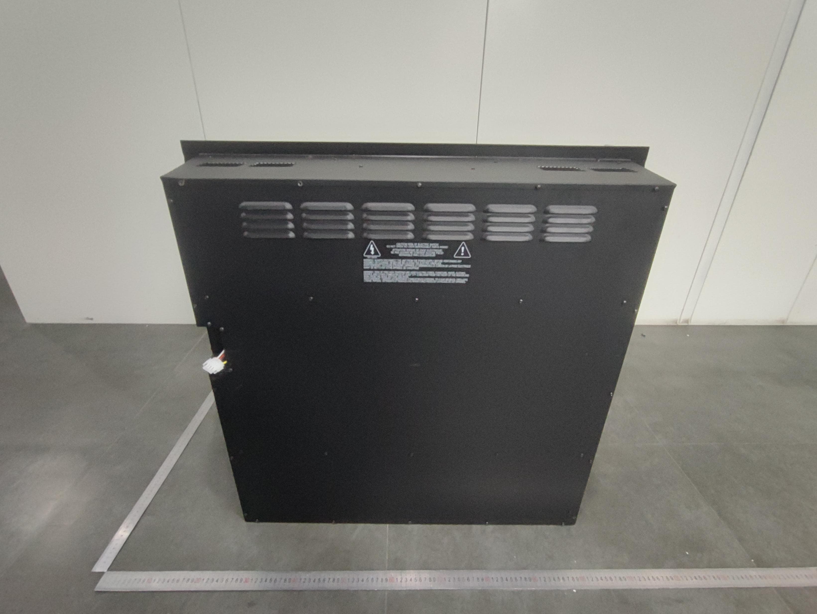
ULE-EF699A
May 01, 2026Electric Fireplace
Equipment Class
DTS - Digital Transmission System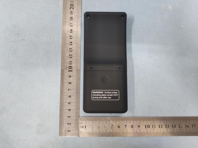
ULE2564-110
Nov 04, 2020IFT-RC400IntelliFire Touch Remote Control
Equipment Class
DXX - Part 15 Low Power Communication Device Transmitter
ULE2564-100
Nov 04, 2020IFT-RC150 IntelliFire Touch Wireless Wall Switch
Equipment Class
DXX - Part 15 Low Power Communication Device Transmitter
ULE2326-130
Mar 14, 2014Fireplace system controller (ECM)
Equipment Class
DXX - Part 15 Low Power Communication Device Transmitter
ULE2326-110
Mar 14, 2014Fireplace system controller (Remote)
Equipment Class
DXX - Part 15 Low Power Communication Device Transmitter