ULERF-5AFIREPLACE REMOTE CONTROLS
Hearth & Home Technologies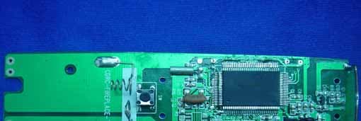
Click to zoom
Application Details
- Equipment Class
- DSC - Part 15 Security/Remote Control Transmitter
- Date of Grant
- Sep 28, 2006
- Application Purpose
- Original Equipment
- Date of Application
- Sep 28, 2006
- Equipment Note
- FIREPLACE REMOTE CONTROLS
- Frequency Range
- 303.80000000 - 303.80000000
- Company
- Hearth & Home Technologies
- Country
- United States
Documents & Files
Document Text
Text extracted from the exhibit documents filed with the FCC. Open a document above to read the original.
Users Manual
1 FOR REVIEW ONLY FCC REQUIREMENTS WARNING: CHANGES OR MODIFICATIONS TO THIS UNIT NOT EXPRESSLY APPROVED BY THE PARTY RESPONSIBLE FOR COMPLIANCE COULD VOID THE USER'S AUTHORITY TO OPERATE THE EQUIPMENT. NOTE: This equipment has been tested and found to comply with the limits for a Class B digital device, pur- suant to Part 15 of the FCC Rules. These limits are designed to provide reasonable protection against harm- ful interference in a residential installation. This equip- ment generates, uses, and can radiate radio frequency energy and, if not installed and used in accordance with the instructions, may cause harmful interference to radio communications. However, there is no guaran- tee that interference will not occur in a particular instal- lation. Canadian Equipment Requirements This digital apparatus does not exceed the (Class A/ Class B)* limits for radio noise emissions from digital apparatus set out in the Radio Interference Regulations of the Canadian Department of Communications. Le present appareil numerique n'emet pas de bruits radioelectriques depassant les limites applicables aux appareils numeriques (de la class A/de la class B)* prescrites dans le Reglement sur le brouillage radioelectrique edicte par le ministere des Communi- cations du Canada. This device complies with RSS-210 of Industry and Sci- ence Canada. Operation is subject to the following two conditions: (1) this device may not cause interference, and (2) this device must accept any interference, in- cluding interference that may cause undesired opera- tion of the device. Hearth & Home Technologies Inc. 20802 Kensington Boulevard, Lakeville, MN 55044 100-906E 4/06 SMART-STAT-II Remote Control Kits - Installation and Operating Instructions - INTRODUCTION The remote control system can be operated thermo- statically or manually from the transmitter. The system operates on radio frequencies (RF) within a 20 foot range. Can be used with DSI, IPI or Standing Pilot systems. This remote control kit has a hand held transmitter that can be used as a remote on/off or as a thermostat. The transmitter display shows the current room tempera- ture, target temperature, timer setting, on/off status, low battery indicator, current time and burner/valve op- eration. Electrical ratings for the receiver are: 110 VAC, 60 Hz. If pertinent, see additional fireplace wiring diagrams on pages 8 to 10. INSTALLATION PRECAUTIONS This remote control kit is tested and safe when installed in accordance with this installation manual. Installa- tion of this kit MUST be done by a qualified service technician. It is the responsibility of the installer to read all instructions before starting installation and to follow these instructions carefully during installation. Modifi- cation of the remote control system or any of its com- ponents will void the warranty and may cause a fire hazard. NOTE: The factory installed junction box in the gas fireplace must be wired with 110 VAC before installing this kit. See Installation Instructions sec- tion. CAUTION: All wiring should be done by a qualified electrician and shall be in compliance with local codes and with the National Electric Code ANSI/NFPA No. 70-current (in the United States), or with the current CSA C22.1 Canadian Electric Code (in Canada). WARNING: DO NOT CONNECT 110-120 VAC WIRING TO THE GAS CONTROL VALVE OF THIS APPLIANCE. 2 FOR REVIEW ONLY Figure 1 REMOTE RECEIVER Important: The remote receiver should be posi- tioned close to front in right or left corner. The remote receiver is powered by 110-120VAC. It plugs into a standard polarized duplex receptacle. Locating Receiver and Operating Functions This remote receiver can be positioned under the fire- box in the control compartment of the fireplace if ambi- ent temperatures do not exceed 170 0 F. This system is designed to remotely operate the gas valve. INSTALLATION INSTRUCTIONS Installing Electrical Service to the Junction Box WARNING: TURN ELECTRICAL POWER OFF AT THE CIRCUIT BREAKER BEFORE BEGIN- NING THIS INSTALLATION. NOTE: Some appliances do not have a cover plate. Instead, there is a hole through which the Romex clamp is attached to the outer wrap. 1. Remove the electrical cover plate from the lower side of the fireplace. Remove the knock-out from the plate and attach the Romex clamp (screws to the outside) (see Figure 1). 2. Feed the electrical service wires through the Romex clamp and secure the wires to the clamp. 3. Using the wire nuts provided, connect the service wires to the junction box. The black wires to the black service wire, the white wires to the white ser- vice wire, and the service ground wire to the ground stud of the junction box. 4. Re-attach the cover plate to the out- side of the fireplace. WARNING: LEAVE ELECTRICAL POWER OFF AT THIS TIME. DO NOT RESTORE POWER UNTIL THE REMOTE CONTROL SYSTEM IS COMPLETELY INSTALLED. ACCESS HOLE COVER PLATE 110 VAC SERVICE RECEIVER WIRING INSTRUCTIONS Incorrect wiring connections WILL cause damage to the gas valve or electronic module operating the gas appli- ance and may also damage the remote receiver. Wiring Millivolt Valves Connect the remote receiver by connecting each of the two wires leading from the remote receiver to either of the two wire TH terminals on the gas valve (see Fig- ure 2). Normally it does not matter which wires go to which terminal. Figure 2. Wiring Millivolt Valves Alternative Wiring for units with a wall switch Disconnect the wall switch wire from the TH terminal on the valve and connect this wire to male connector supplied on the receiver. Con- nect remaining female connector from receiver to the TH terminal on the valve. REMOTE RECEIVER THERMOPILE/ PILOT LIGHT TERMINAL BLOCK ON MILLIVOLT GAS VALVES TH TP WALL SWITCH TP TH 3 FOR REVIEW ONLY Wiring Electronic Spark Ignitions The remote control receiver can be wired, in series, to a 24VAC transformer, which controls an electronic igni- tion module (see Figure 3). 1. Connect the neutral wire from the 24VAC t…
Text truncated - open the document above for the full version.
Block Diagram
RF-5A(BATT)TX 2006/7/25DZW C&D A3 11 REV:SIZE:CODE: DRAWN:DATED: DATED:CHECKED: QUALITY CONTROL:DATED: DATED:RELEASED: COMPANY: TITLE: DRAWING NO: SHEET: OFSCALE: REVISION RECORD APPROVED:ECO NO: A B D DATE: 123456 D C A B C LTR HT7027 HT49R50 CPU DATA LOW BATTERY DETECT RF-5A(BATT)TX BLOCK DIAGRAM LCD DISPLAY THERMO RESISTER BACKLIGHT 12 X1 4.0MHZ 1 ANT 1 2 BATT E B C Q1 1 2 X2 32.768KHZ 1 2 SAW 303.8MHZ KA LED KA KA KA 12 MODE 12 UP 12 DOWN 12 SET 12 TIMER 12 TH 12 CP-LOCK VBATT PDF created with pdfFactory Pro trial version www.pdffactory.com
External Photos
EUT - Front View EUT - Back View
ID Label/Location Info
FCC ID Label Sample for Model: RF-5A(TX)/STAT(RX)/BATT(RX) FCC ID: ULERF-5A This device complies with Part 15 of the FCC Rules. Operation is subject to the following two conditions: (1) This device may not cause harmful interference, and (2) This device must accept any interference received, including interference that may cause undesired operation.
Internal Photos
PCB-Front View Back View
Operational Description
Circuit Description The TX unit is made up of Modulation transmitter, Data memory, Thermo detector, backlight, key board interface, LCD display, low battery detector and CPU clock frequency circuit. 1. The TX unit adopts 2pcs AAA Alkaline battery supply. Crystal X1 4.0MHz and X2 32.768KHz provides U1 CPU HT49R50 with working clock frequency. U3 HT 7027 outputs a low level to U1 when the battery is lower than 2.7V, and then LCD will display low Batter Sign. 2. U1 outputs a group data to Q2 when MODE button is pressed. SAW & Q2 are the modulation transmitter’s main components for modulation mode of ASK. SAW keeps transmitter frequency at 303.8MHz +/-75KHz. Meanwhile, U1 PIN99 outputs a high level to Q1 to drive LED1, LED2, LED3, LED4 light on. The LEDs will be auto off after 8s. 3. U2 (93LC 46B) is a Eeprom component. Thermo-resistor sends detected data to U1 for dealing with, and the results will be showed by LCD . 4. Buttons of UP, DOWN, MODE, SET, TIMER and CP-LOCK are U1 Interface Circuit. LCD displays all U1 processed results.
Schematics
123456 A B C D 654321 D C B A Title NumberRevisionSize B Date:14-Jul-2006Sheet of File:E:\dzw\壁炉资料\RF5A.DdbDrawn By: 1 2 3 4 5 6 7 8 9 10 11 12 13 14 15 16 17 18 19 20 21 22 23 24 25 26 27 28 29 30 3132333435363738394041424344454647484950 51 52 53 54 55 56 57 58 59 60 61 62 63 64 65 66 67 68 69 70 71 72 73 74 75 76 77 78 79 80 81828384858687888990919293949596979899100 U1 HT49R50A-1 LCD C6 104 C8 104 C14 104 C5 104 R13 10R R9 47K TH1 TH103 C1 104 C3 105 UP TIME SWITCH SET MODE DOWN R8 47K R7 47K R6 47K R9 47K R4 47K R3 47K 1 2 3 45 6 7 8 U2 93LC46B R2 100R R5 100R R19 10K A K D1 1N5819 VCC 2 GND 3 RESET 1 U3HT7027 C2 103 R1 10R BAT 3V VCC3V C16 102 C9 104 R16 10K X1 4M X2 32.768K VCC3V C10 20P C11 20P C12 10P C13 10P R15 4.7K 2 1 3 Q1 8050 A K LED1 A K LED2 A K LED3 A K LED4 R12100R R14 100R VCC3V R19 24K 2 1 3 Q2 2SC3356 R18 100R C15 6P 1 1 2 2 3 3 SAW 303.8MHZ R17 2.2R C20 102 VCC3V C4 104 C7 100UF/10V RF-5A发射器原理图 C19 2.2P PDF 文件使用 "pdfFactory Pro" 试用版本创建 www.fineprint.cn
Test Report
FCC TEST REPORT Page 1 of 24 FCC ID : ULERF-5A Applicant : Hearth & Home Technologies 20802 Kensington Blvd Lakeville MN USA 55044 Equipment Under Test (EUT) : Product description : Fireplace Remote Controls Model No. : RF-5A(TX)/STAT(RX)/BATT(RX) Standards : FCC 15 Subpart C Paragraph 15.231 Date of Test : September 28, 2006 Test Engineer : Tiger Su Reviewed By : PERPARED BY: Waltek Services (Shenzhen) Co., Ltd. 8C,West Tower, Aidi Building, No.5003 Binhe Rd, Futian District, Shenzhen518045, Guangdong, China. Tel: 86-755-83551033 Fax: 86-755-83552400 Hearth & Home Technologies FCC ID: ULERF-5A Page 2 of 24 2 Contents Page 1 COVER PAGE..........................................................................................................................................................1 2 CONTENTS ..............................................................................................................................................................2 3 TEST SUMMARY....................................................................................................................................................5 4 GENERAL INFORMATION..................................................................................................................................6 4.1 CLIENT INFORMATION............................................................................................................................................6 4.2 GENERAL DESCRIPTION OF E.U.T...........................................................................................................................6 4.3 DETAILS OF E.U.T. .................................................................................................................................................6 4.4 DESCRIPTION OF SUPPORT UNITS...........................................................................................................................6 4.5 STANDARDS APPLICABLE FOR TESTING..................................................................................................................6 4.6 TEST FACILITY........................................................................................................................................................7 4.7 TEST LOCATION......................................................................................................................................................7 5 EQUIPMENT USED DURING TEST ...................................................................................................................8 6 CONDUCTED EMISSION TEST ..........................................................................................................................9 6.1 TEST EQUIPMENT....................................................................................................................................................9 6.2 TEST PROCEDURE...................................................................................................................................................9 6.3 CONDUCTED TEST SETUP.....................................................................................................................................10 6.4 EUT OPERATING CONDITION...............................................................................................................................10 6.5 CONDUCTED EMISSION LIMITS.............................................................................................................................11 6.6 CONDUCTED EMISSION TEST RESULT...................................................................................................................11 7 RADIATION EMISSION TEST...........................................................................................................................12 7.1 TEST EQUIPMENT..................................................................................................................................................12 7.2 MEASUREMENT UNCERTAINTY.............................................................................................................................12 7.3 TEST PROCEDURE.................................................................................................................................................12 7.4 RADIATED TEST SETUP.........................................................................................................................................13 7.5 SPECTRUM ANALYZER SETUP...............................................................................................................................13 7.6 CORRECTED AMPLITUDE & MARGIN CALCULATION............................................................................................14 7.7 SUMMARY OF TEST RESULTS................................................................................................................................14 7.8 EUT OPERATING CONDITION...............................................................................................................................15 7.9 RADIATED EMISSIONS LIMIT.................................................................................................................................15 7.10 RADIATED EMISSIONS TEST RESULT................................................................................................................16 7.10.1 Radiated Emission Data.............................................................................................................................16 8 PERIODIC OPERATION .....................................................................................................................................18 9 BAND EDGE ..........................................................................................................................................................19 9.1 TEST PROCEDURE.............................................................................................…
Text truncated - open the document above for the full version.
Test Setup Photos
Radiation Emission Test View For 30MHz-1000MHz Radiation Emission Test View For 1GHz-5GHz
Contact Information
Applicant
Davd C Lyons(VP R & D HHT)
Test Firm
SGS-CSTC Standards Technical Services Co.,Ltd.June Zhang
Technical Specifications
| # | Rule Parts | Frequency Range | Power Output |
|---|---|---|---|
| 1 | 15.231 | 303.8 MHz - 303.8 MHz | - |
Other Applications from Hearth & Home Technologies
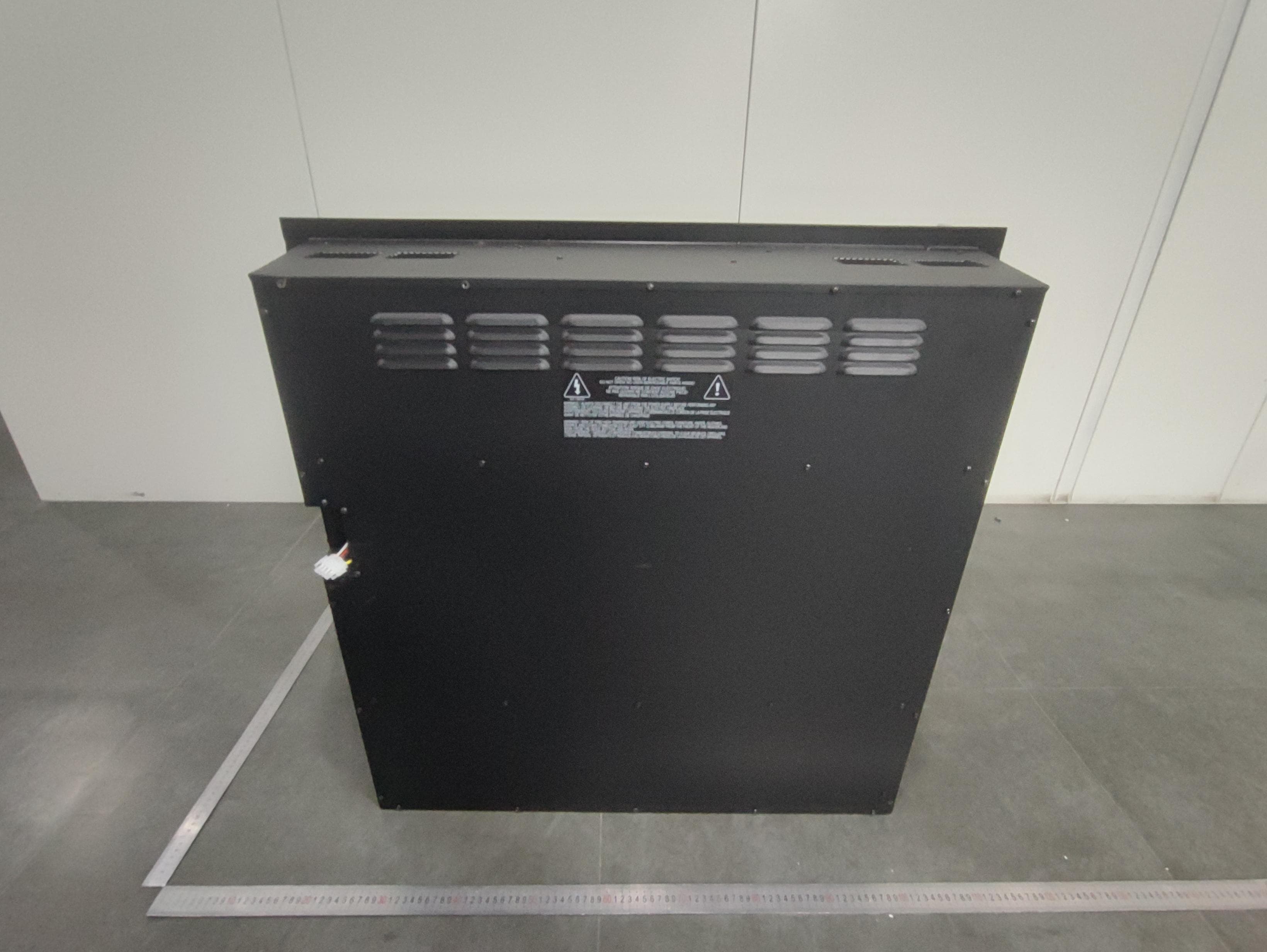
ULE-EF699A
May 01, 2026Electric Fireplace
Equipment Class
DTS - Digital Transmission System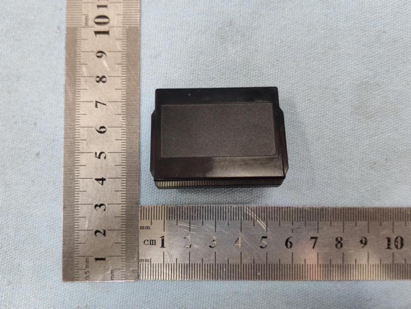
ULE2564-130
Nov 15, 2020IntelliFire Touch Technology -Electronic Control Module(IFT-ECM)
Equipment Class
DXX - Part 15 Low Power Communication Device Transmitter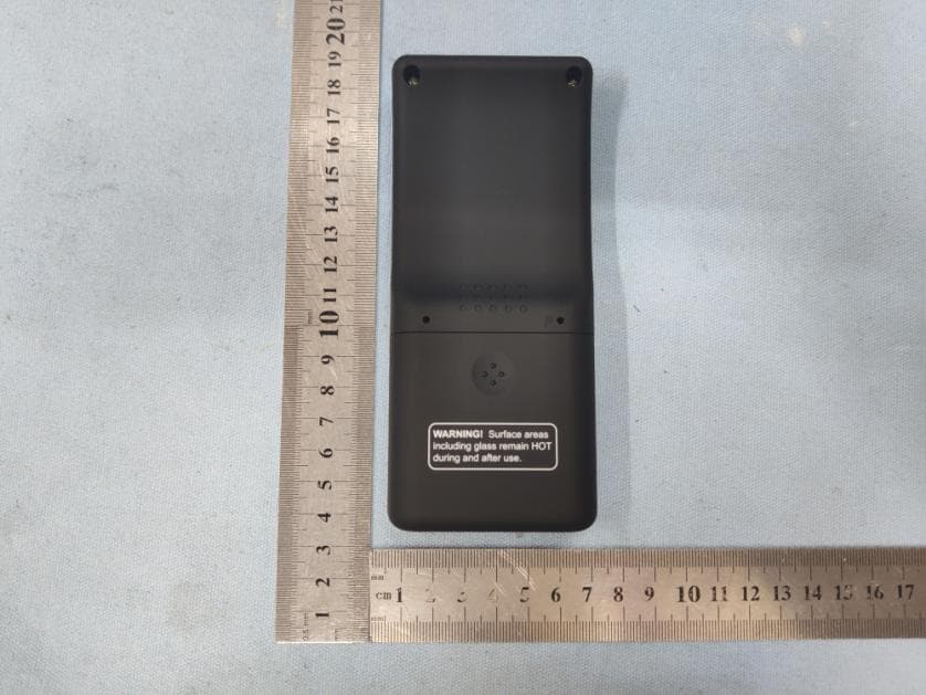
ULE2564-110
Nov 04, 2020IFT-RC400IntelliFire Touch Remote Control
Equipment Class
DXX - Part 15 Low Power Communication Device Transmitter
ULE2564-100
Nov 04, 2020IFT-RC150 IntelliFire Touch Wireless Wall Switch
Equipment Class
DXX - Part 15 Low Power Communication Device Transmitter
ULE2326-130
Mar 14, 2014Fireplace system controller (ECM)
Equipment Class
DXX - Part 15 Low Power Communication Device Transmitter