ULERF-5ANREMOTE CONTROL KITS
Hearth & Home Technologies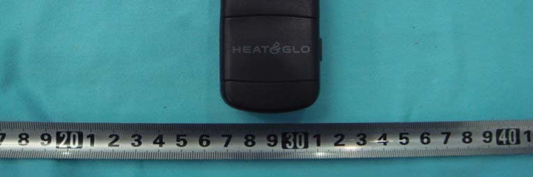
Click to zoom
Application Details
- Equipment Class
- DSC - Part 15 Security/Remote Control Transmitter
- Date of Grant
- Aug 29, 2007
- Application Purpose
- Original Equipment
- Date of Application
- Aug 29, 2007
- Equipment Note
- REMOTE CONTROL KITS
- Frequency Range
- 433.92000000 - 433.92000000
- Company
- Hearth & Home Technologies
- Country
- United States
Documents & Files
Document Text
Text extracted from the exhibit documents filed with the FCC. Open a document above to read the original.
Users Manual
SMART-BATT-II Remote Control Kits - Installation and Operating Instructions - INTRODUCTION The remote control system can be operated thermostati- cally or manually from the transmitter. The system oper- ates on radio frequencies (RF) within a 20 foot range. Can be used with IPI or Standing Pilot systems. This remote control kit has a hand held transmitter that can be used as a remote on/off or as a thermostat. The trans- mitter display shows the current room temperature, target temperature, timer setting, on/off status, low battery indi- cator, current time and burner/valve operation. If pertinent, see additional fireplace wiring diagrams on the following pages. INSTALLATION PRECAUTIONS This remote control kit is tested and safe when installed in accordance with this installation manual. Installation of this kit MUST be done by a qualified service technician. It is the responsibility of the installer to read all instructions before starting installation and to follow these instructions care- fully during installation. Modification of the remote control system or any of its components will void the warranty and may cause a fire hazard. CAUTION: All wiring should be done by a qualified electri- cian and shall be in compliance with local codes and with the National Electric Code ANSI/NFPA No. 70-current (in the United States), or with the current CSA C22.1 Canadian Electric Code (in Canada). WARNING: DO NOT CONNECT 110-120 VAC WIRING TO THE GAS CONTROL VALVE OF THIS APPLIANCE. FCC REQUIREMENTS FCC NOTE: The manufacturer is not responsible for any radio or TV interference caused by unauthorized modifications to this equipment. Such modifications could void the user's authority to operate the equipment. NOTE: This equipment has been tested and found to com- ply with the limits for a Class B digital device, pursuant to Part 15 of the FCC Rules. This device complies with Part 15 of the FCC Rules. Operation is subject to the following two conditions: (1) this device may not cause harmful interference, and (2) this device must accept any interference received, including interference that may cause undesired operation. These limits are designed to provide reasonable protection against harmful interference in a residential installation. This equipment generates, uses, and can radiate radio frequency energy and, if not installed and used in accordance with the instructions, may cause harmful interference to radio communications. However, there is no guarantee that interference will not occur in a particular installation. If this equipment does cause harmful interference to radio or television reception, which can be determined by turning the equipment off and on, the user is encouraged to try to correct the interference by one or more of the following measures: - Reorient or relocate the receiving antenna. - Increase the separation between the equipment and re- ceiver. - Connect the equipment into an outlet on a circuit differ- ent from that to which the receiver is connected. - Consult the dealer or an experienced radio TV techni- cian for help. Canadian Equipment Requirements This digital apparatus does not exceed the (Class A/Class B)* limits for radio noise emissions from digital apparatus set out in the Radio Interference Regulations of the Cana- dian Department of Communications. Le present appareil numerique n'emet pas de bruits radioelectriques depassant les limites applicables aux appareils numeriques (de la class A/de la class B)* prescrites dans le Reglement sur le brouillage radioelectrique edicte par le ministere des Com- munications du Canada. This device complies with RSS-210 of Industry and Sci- ence Canada. Operation is subject to the following two con- ditions: (1) this device may not cause interference, and (2) this device must accept any interference, including interfer- ence that may cause undesired operation of the device. Printed in China Copyright 2006, Hearth & Home Technologies Inc. 20802 Kensington Boulevard, Lakeville, MN 55044 100-909G 12/06 1 2 RECEIVER WIRING INSTRUCTIONS Incorrect wiring connections WILL cause damage to the gas valve or electronic module operating the gas appliance and may also damage the remote receiver. Make sure the remote receiver switch is in the OFF position. Use 18 gauge stranded wires for connec- tions between the terminal wiring block on the milli- volt gas valve or electronic module and the wire ter- minals on the remote receiver. For best results, use wire measuring no longer than 20 ft. Wiring Millivolt Valves Connect the remote receiver by connecting each of the two wires leading from the TH terminals on the gas valve (see Figure 2) to either of the two wire terminals on the receiver. Normally it does not matter which wires go to which terminal. Figure 2. Wiring Millivolt Valves HEARTH MOUNT The remote receiver can be placed on the fireplace hearth (see Figure 1), or under the fireplace behind the control access panel. Position it close to the front in the right or left corner where the ambient tempera- ture inside the receiver case does not exceed 120 0 F. NOTE: The remote receiver will only respond to trans- mitter when the switch cover on the receiver is in the REMOTE position. If the system does not respond to the transmitter, see MATCHING SECURITY CODES, and recheck battery position in the remote receiver. Figure 3. A. Wiring Millivolt Valve with Rocker PIEZO 3-ROCKER SWITCH ASSEMBLY RED WHITE VALV E PILOT THERMOCOUPLE Alternative Wiring for units with a Wall Switch REMOTE RECEIVE R THERMOPILE/ PILOT LIGHT TERMINAL BLOC K ON MILLIVOLT GAS VALVES TH TP WALL SWITCH TP TH Figure 1. Hearth Mount Receiver WIRE TERMINALS ON/OFF REMOTE SLIDE SWITCH 3 Figure 4. Millivolt with Rocker Switch and Receiver Figure 5. Millivolt with 3 Wire If your fireplace is wired like Figure 3 find the leads on back of the switch marked “For use with remote or wall switch only” and take the leads and plug them into wire lead on remote receiver box (see Figure 4…
Text truncated - open the document above for the full version.
Block Diagram
RF-5A(BATT)TX 2006/7/25 DZW C&D A3 11 REV: SIZE: CODE: DRAWN: DATED: DATED: CHECKED:QUALITY CONTROL: DATED: DATED: RELEASED: COMPANY:TITLE: DRAWING NO: SHEET: OF SCALE: REVISION RECORD APPROVED: ECO NO: ABD DATE: 1 2 3 4 5 6 DCAB C LTR HT7027 HT49R50 CPU DATA LOW BATTERY DETECT RF-5A(BATT)TX BLOCK DIAGRAM LCD DISPLAY THERMO RESISTER BACKLIGHT 1 2 X1 4.0MHZ 1 ANT 12 BATT E B C Q1 1 2 X2 32.768KHZ 1 2 SAW 433.92MHZ K A LED K A K A K A 12 MODE 12 UP 12 DOWN 12 SET 12 TIMER 1 2 TH 12 CP-LOCK VBATT
External Photos
EUT - Front View EUT - Back View
ID Label/Location Info
FCC ID Label Sample for Model: SMART-BATT-II FCC ID: ULERF-5AN This device complies with Part 15 of the FCC Rules. Operation is subject to the following two conditions: (1) This device may not cause harmful interference, and (2) This device must accept any interference received, including interference that may cause undesired operation.
ID Label/Location Info
FCC ID Label This device complies with Part 15 of the FCC Rules. Operation is subject to the following two conditions: (1)this device may not cause harmful interference, and (2) this device must accept any interference received, including interference that may cause undesired operation The Label must not be a stick-on paper. The Label on these products must be permanently affixed to the product and readily visible at the time of purchase and must last the expected lifetime of the equipment not be readily detachable. Proposed Label Location on EUT EUT Bottom View/proposed FCC Mark Location FCC ID: ULERF-5AN This device complies with Part 15 of the FCC Rules.Operation is subject to the following two conditions: 1. This device may not cause harmful interference, and 2. This device must accept any interference received, including interference that may cause undesired operation
Internal Photos
PCB-Front View PCB-Back View
Operational Description
Circuit Description The TX unit is made up of Modulation transmitter, Data memory, Thermo detector, backlight, key board interface, LCD display, low battery detector and CPU clock frequency circuit. 1. The TX unit adopts 2pcs AAA Alkaline battery supply. Crystal X1 4.0MHz and X2 32.768KHz provides U1 CPU HT49R50 with working clock frequency. U3 HT 7027 outputs a low level to U1 when the battery is lower than 2.7V, and then LCD will display low Batter Sign. 2. U1 outputs a group data to Q2 when MODE button is pressed. SAW & Q2 are the modulation transmitter’s main components for modulation mode of ASK. SAW keeps transmitter frequency at 433.92MHz +/-75KHz. Meanwhile, U1 PIN99 outputs a high level to Q1 to drive LED1, LED2, LED3, LED4 light on. The LEDs will be auto off after 8s. 3. U2 (93LC 46B) is a Eeprom component. Thermo-resistor sends detected data to U1 for dealing with, and the results will be showed by LCD . 4. Buttons of UP, DOWN, MODE, SET, TIMER and CP-LOCK are U1 Interface Circuit. LCD displays all U1 processed results.
Schematics
1 2 3 4 56 ABCD 6 5 4 3 2 1 D CBA 123456789 101112131415161718192021222324252627282930 31 32 33 34 35 36 37 38 39 40 41 42 43 44 45 46 47 48 49 50 515253545556575859606162636465666768697071727374757677787980 81 82 83 84 85 86 87 88 89 90 91 92 93 94 95 96 97 98 99 100 U1 HT49R50A-1 LCD C6104 C8104 C14104 C5104 R13 10R R9 47K TH1 TH103 C1104 C3105 UPTIMESWITCHSETMODEDOWN R847K R747K R647K R947K R447K R347K 1234 5678 U2 93LC46B R2100R R5 100R R1910K AK D1 1N5819 VCC 2 GND 3 RESET 1 U3 HT7027 C2103 R110R BAT3V VCC3V C16102 C9104 R1610K X1 4M X2 32.768K VCC3V C1020P C1120P C1210P C1310P R154.7K 2 13 Q18050 AK LED1 AK LED2 AK LED3 AK LED4 R12 100R R14 100R VCC3V R1924K 2 13 Q22SC3356 R18100R C15 3.3P 1 1 2 2 3 3 SAW433.92MHZ R172.2R C2020P VCC3V C4104 C7100UF/10V RF-5A TX C191.0P
Test Report
FCC TEST REPORT Page 1 of 26 FCC ID : ULERF-5AN Applicant : Hearth & Home Technologies 20802 Kensington Blvd Lakeville MN USA 55044 Equipment Under Test (EUT) : Product description : Remote Control Kits Model No. : SMART-BATT-II Standards : FCC 15 Subpart C Paragraph 15.231 Date of Test : August 20, 2007 Test Engineer : Tiger Su Reviewed By : PERPARED BY: Waltek Services (Shenzhen) Co., Ltd. 8C,West Tower, Aidi Building, No.5003 Binhe Rd, Futian District, Shenzhen518045, Guangdong, China. Tel: 86-755-83551033 Fax: 86-755-83552400 Hearth & Home Technologies FCC ID: ULERF-5AN Page 2 of 26 2 Contents Page 1 COVER PAGE..........................................................................................................................................................1 2 CONTENTS ..............................................................................................................................................................2 3 TEST SUMMARY....................................................................................................................................................5 4 GENERAL INFORMATION..................................................................................................................................6 4.1 CLIENT INFORMATION............................................................................................................................................6 4.2 GENERAL DESCRIPTION OF E.U.T...........................................................................................................................6 4.3 DETAILS OF E.U.T. .................................................................................................................................................6 4.4 DESCRIPTION OF SUPPORT UNITS...........................................................................................................................6 4.5 STANDARDS APPLICABLE FOR TESTING..................................................................................................................6 4.6 TEST FACILITY........................................................................................................................................................7 4.7 TEST LOCATION......................................................................................................................................................7 5 EQUIPMENT USED DURING TEST ...................................................................................................................8 6 CONDUCTED EMISSION TEST ..........................................................................................................................9 6.1 TEST EQUIPMENT....................................................................................................................................................9 6.2 TEST PROCEDURE...................................................................................................................................................9 6.3 CONDUCTED TEST SETUP.....................................................................................................................................10 6.4 EUT OPERATING CONDITION...............................................................................................................................10 6.5 CONDUCTED EMISSION LIMITS.............................................................................................................................11 6.6 CONDUCTED EMISSION TEST RESULT...................................................................................................................11 7 RADIATION EMISSION TEST...........................................................................................................................12 7.1 TEST EQUIPMENT..................................................................................................................................................12 7.2 MEASUREMENT UNCERTAINTY.............................................................................................................................12 7.3 TEST PROCEDURE.................................................................................................................................................12 7.4 RADIATED TEST SETUP.........................................................................................................................................13 7.5 SPECTRUM ANALYZER SETUP...............................................................................................................................13 7.6 CORRECTED AMPLITUDE & MARGIN CALCULATION............................................................................................14 7.7 SUMMARY OF TEST RESULTS................................................................................................................................14 7.8 EUT OPERATING CONDITION...............................................................................................................................15 7.9 RADIATED EMISSIONS LIMIT.................................................................................................................................15 7.10 RADIATED EMISSIONS TEST RESULT................................................................................................................16 7.10.1 Radiated Emission Data.............................................................................................................................16 8 PERIODIC OPERATION .....................................................................................................................................18 9 BAND EDGE ..........................................................................................................................................................21 9.1 TEST PROCEDURE..................................................................................................................…
Text truncated - open the document above for the full version.
Test Setup Photos
Radiation Emission Test View For 30MHz-1000MHz Radiation Emission Test View For 1GHz-5GHz
Contact Information
Applicant
Davd C Lyons(VP R & D HHT)
Test Firm
SGS-CSTC Standards Technical Services Co.,Ltd.June Zhang
Technical Specifications
| # | Rule Parts | Frequency Range | Power Output |
|---|---|---|---|
| 1 | 15.231 | 433.92 MHz - 433.92 MHz | - |
Other Applications from Hearth & Home Technologies
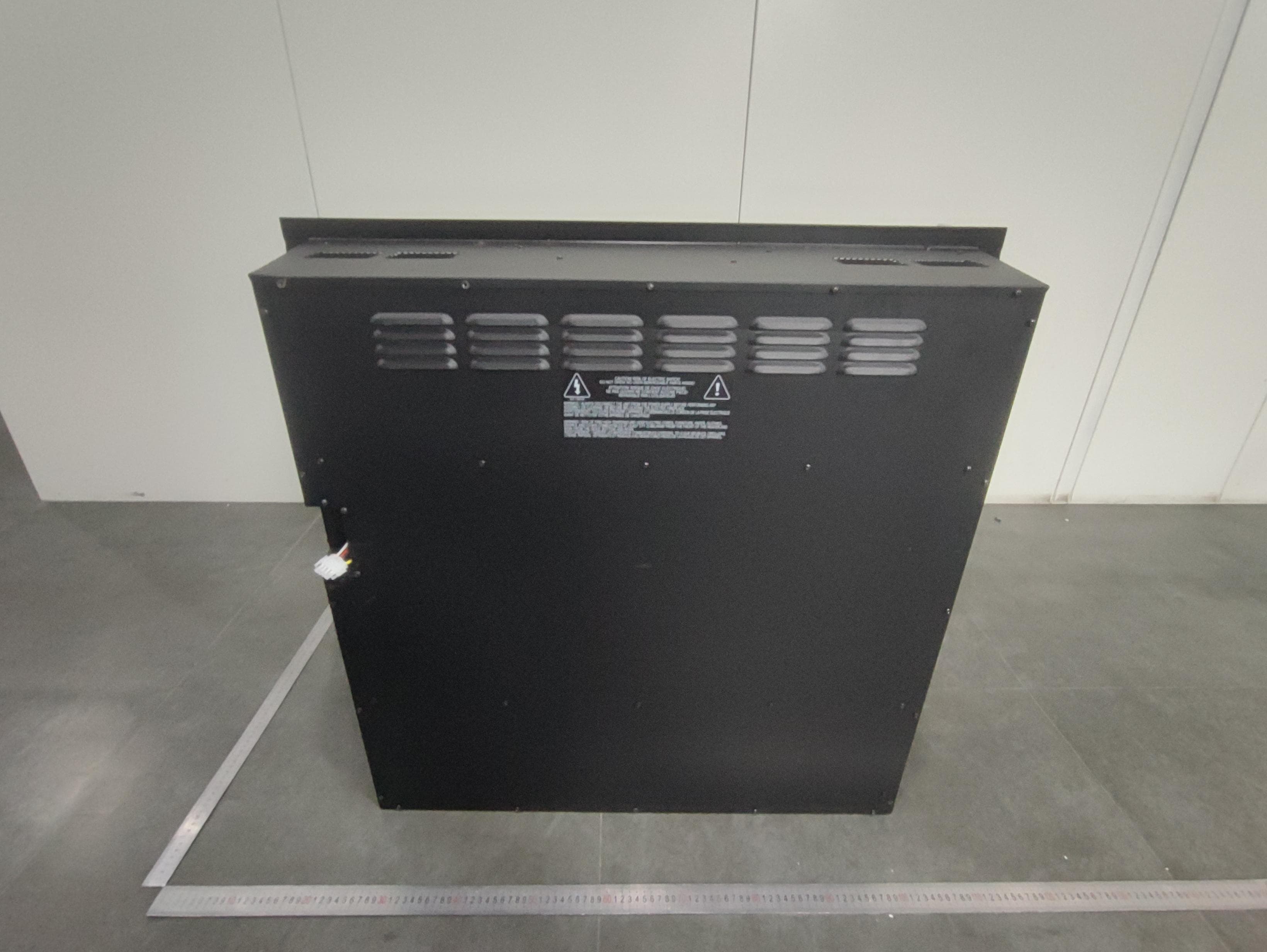
ULE-EF699A
May 01, 2026Electric Fireplace
Equipment Class
DTS - Digital Transmission System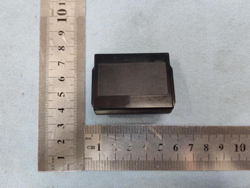
ULE2564-130
Nov 15, 2020IntelliFire Touch Technology -Electronic Control Module(IFT-ECM)
Equipment Class
DXX - Part 15 Low Power Communication Device Transmitter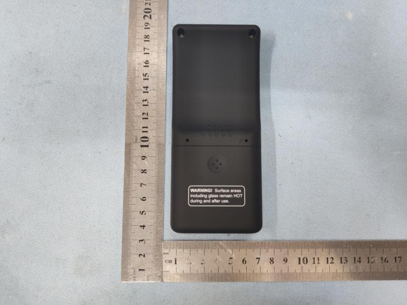
ULE2564-110
Nov 04, 2020IFT-RC400IntelliFire Touch Remote Control
Equipment Class
DXX - Part 15 Low Power Communication Device Transmitter
ULE2564-100
Nov 04, 2020IFT-RC150 IntelliFire Touch Wireless Wall Switch
Equipment Class
DXX - Part 15 Low Power Communication Device Transmitter
ULE2326-130
Mar 14, 2014Fireplace system controller (ECM)
Equipment Class
DXX - Part 15 Low Power Communication Device Transmitter