UOB-G10TIIWireless Transmitter
Line 6 Digital Wireless Inc.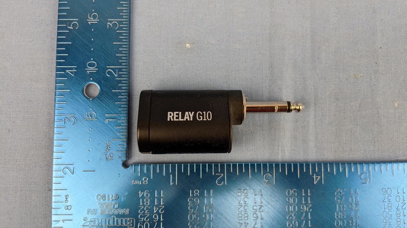
Click to zoom
Application Details
- Equipment Class
- DTS - Digital Transmission System
- Date of Grant
- Dec 03, 2020
- Application Purpose
- Original Equipment
- Date of Application
- Dec 03, 2020
- Equipment Note
- Wireless Transmitter
- Frequency Range
- 2402.00000000 - 2478.00000000
- Company
- Line 6 Digital Wireless Inc.
- Country
- United States
Documents & Files
Document Text
Text extracted from the exhibit documents filed with the FCC. Open a document above to read the original.
Users Manual
RELAY G10TII / G10 / G10S PILOT’S GUIDE MANUEL DE PILOTAGE PILOTENHANDBUCH MANUAL DEL PILOTO パイロット・ガイド 新手指南 40-00-0569 - A www.line6.com/manuals © 2020 Yamaha Guitar Group, Inc. All rights reserved. ® © 2020 Yamaha Guitar Group, Inc. All rights reserved. Line 6, the Line 6 logo, Relay, Spider, and POD Go are trademarks or registered trademarks of Yamaha Guitar Group, Inc. in the U.S. and/or other jurisdictions. Supplier's Declaration of Conformity 47 CFR § 2.1077 Compliance Information Unique Identifiers: Line 6 Relay G10TII, Line 6 Relay G10, Line 6 Relay G10R, Line 6 Relay G10S, Line 6 Relay G10SR Responsible Party - U.S. Contact Information: Yamaha Guitar Group, Inc. 26580 Agoura Road Calabasas, CA 91302-1921 (818) 575-3600 https://line6.com/ FCC Compliance Statement: This device complies with Part 15 of the FCC Rules. Operation is subject to the following two conditions: (1) This device may not cause harmful interference, and (2) this device must accept any interference received, including interference that may cause undesired operation. FCC ID: UOB-G10TII IC: 6768A-G10TII 2 System Overview • Wireless freedom in any size venue, home, or office • Easy to use—no setup required • Automatically chooses the best channel for true playing freedom • Up to 8 hours of playing time per charge • Optional manual channel selection for setups with multiple wireless units (Relay G10S only) • Best in class sound quality provided by: • 24-bit uncompressed digital transmission • Best in class DAC and ADC provide super low noise transmission (better than 110dB dynamic range) • Up to 50 feet (15 meters) for Relay G10, or up to 130 feet (40 meters) for Relay G10S, line-of-sight range 2.4GHz Wireless Since the Relay ® is a 2.4GHz wireless system, please avoid placing the receiver next to other RF transmitting equipment. We recommend that you install the G10 or G10S receiver at least 10 feet (3 meters) away from RF transmitters (e.g., WiFi routers). The Relay system automatically selects the best channel when the transmitter is docked (for the G10S receiver, its Channel Selector needs to be set to AUTO). After changing WiFi or other 2.4GHz wireless channels, please dock the transmitter in the receiver for at least 10 seconds. What's in the Box RELAY G10TII • Relay G10TII Transmitter • Pilot's Guide and End User License Agreement RELAY G10 • Relay G10TII Transmitter (not included in G10R Receiver Separate) • Relay G10 Receiver • USB-A to Micro-USB cable • Universal USB Power Supply (5V-1A) kit with international AC adapter kit. • Pilot's Guide and End User License Agreement RELAY G10S • Relay G10TII Transmitter (not included in G10SR Receiver Separate) • Relay G10SR Receiver • 9V DC Power Supply • USB-A to Micro USB-B Cable • Pilot's Guide and End User License Agreement 3 Getting Started Using the Relay G10TII Transmitter with a Relay G10 or G10S Receiver 1. Insert the Relay G10TII transmitter all the way into the receiver dock to allow the battery to charge. A green steady LED on the transmitter indicates the transmitter is fully charged. 2. While the G10TII is docked in the receiver, the system scans the environment and automatically selects the optimal wireless channel. The G10S receiver's channel selector must be set to AUTO for this step. Relay G10Relay G10S 3. Insert the G10TII transmitter into your instrument. 4. Connect the receiver to a power source using the power adapter provided with your device. Connect the Relay G10 or G10S receiver's 1/4" Instrument Output into an amp or FX unit. Relay G10Relay G10S 4 5. For use as a DI with bass and acoustic guitars, connect the Relay G10 or G10S receiver's XLR DI Out to a mixer or audio interface. Relay G10 Relay G10S Using a Relay G10TII Transmitter with Relay-Ready Devices In addition to using a Line 6 wireless receiver, the Relay G10TII transmitter also works with a number of select Relay-Ready devices, such as select Line 6 Spider ® V amplifiers and the POD Go ® Wireless guitar processor (please also see https://line6. com/g10info/ for more info). 1. Insert the Relay G10TII transmitter into the INPUT jack (Spider V) or GUITAR IN jack (POD Go Wireless) and power your device on. MODE TAP BA DC EDIT / EXIT TUNER EXP 1 EXP 2 WAH VOL ACTION PAGEPAGE VIEW WIRELESS The Relay-Ready device charges the G10TII transmitter, as well as scans the environment, and automatically selects the optimal wireless channel and frequency. 2. Once fully charged, insert the G10TII transmitter into your instrument. Please refer to your Spider V Pilot's Guide, POD Go Wireless Owner's Manual, or other Relay-Ready product's documentation for additional details. 5 Relay G10TII Transmitter Details 23 1 1. Battery Status - This LED illuminates green when the transmitter is powered on and while more than 30 minutes of operating time remains. The LED flashes red when less than 30 minutes of operating time remain—also see "Important Information About the G10TII Transmitter" on page 6 for additional LED states. When the transmitter is plugged into the receiver for charging, a flashing red LED indicates less than 30 minutes of battery operation, a flashing green LED indicates more than 30 minutes of battery operation, and a steady green LED indicates a fully charged transmitter. 2. 1/4" Plug - Plugs into instrument. 3. Antenna - The calibrated internal antenna avoids damage or deformity in normal use. Avoid covering the antenna area with metallic fabrics or accessories, and avoid direct contact with parts of the performer’s body for best results. Sleep Mode - To extend battery life, sleep mode is activated after a period of 4 minutes where no audio input is detected. The transmitter “wakes up” automatically when the instrument is played. 6 Important Information About the G10TII Transmitter • The recommended charging temperature range of the G10TII transmitter is specified as 50° F to 86° F (10° C to 30° C). • The recommended operating temperature range of the G10TII transmitter is specified a…
Text truncated - open the document above for the full version.
Users Manual
THIS PAGE FOR REFERNCE ONLY USE ARTWORK ON FOLLOWING PAGES SHOWNG AS PRINTED 4 UP: Score and fold at 159 mm Yamaha Guitar Group, Inc.: 26580 Agoura Road, Calabasas, CA 91302-1921 USA © 2020 Yamaha Guitar Group, Inc. All rights reserved. Line 6 and the Line 6 logo are trademarks or registered trademarks of Yamaha Guitar Group, Inc. in the U.S. and/or other jurisdictions. IMPORTANT SAFETY INSTRUCTIONS SAFETY & COMPLIANCE MANUAL You should read these Important Safety Instructions. Keep these instructions in a safe place. MANUEL DE SÉCURITÉ ET DE CONFORMITÉ SICHERHEITS- UND KONFORMITÄTSHANDBUCH MANUAL DE SEGURIDAD Y CUMP LIMIENTO 安全与合规手册 40-00-0376 Rev M © 2020 Yamaha Guitar Group, Inc. All rights reserved. ® REVISIONS First release for production. Jason Lynn 1/20/2016 A Rewrite for entire Japan segment of manual. Updated portions of French and english to be verbatim. Jason Lynn 5/20/2016 B Deleted content on page 6. Jason Lynn 9/19/2016 C Updated Japan segment. Jason Lynn 11/09/2016 D Added new RFQ statement, all languages S.Fazio 4/10 /2017 E Added CAUTION statement for removing grille F Added Energy label at end of Spanish manual G S.Fazio 12/21/2017 S.Fazio 12/21/2017 Added new electircal, FCC warnings, all languages. Revised all legal, per Davd Kekst. New Japan version provided by YGG. H I S.Fazio 07/29/2019 New Japan version added to replace incorrect Japan version used in Rev H. No changes to other languages. S.Fazio 8/30/2019 J Revised 3 bullet points in English and French - No changes to other languages. S.Fazio 11/07/2019 K Added 3 bullet points end of last pg. for DC-3h power supply reqs., all languages. English + Big 5. S.Fazio 03/24/2020 L Revised “Eficiencia Energetica” image from “V” to “VI” per requirement, M Revised Eng and French - added new FCC rules pg 1.Revised Japan language only, added “Compliance with harmonic currents” statement. SFazio 12/3/2020 (Spanish language only). S.Fazio 04/28/2020 26580 Agoura Road Calabasas, CA 91302 USA voice (818) 575-3733 fax (818) 575-3601 Part Name/Number: Prepared by:Date: Line 6, Manual Safety & Compliance Standard Part #: 40-00-0376 Steve Fazio Dec. 3, 2020 Manual is 159mm x 83mm. Reference above shows example of 4 up layout , 2 pagers per side. Use quality sheets. Use compliant ink only. REVISION M Specifications / Notes: IMPORTANT SAFETY INSTRUCTIONS SAFETY & COMPLIANCE MANUAL You should read these Important Safety Instructions. Keep these instructions in a safe place. MANUEL DE SÉCURITÉ ET DE CONFORMITÉ SICHERHEITS- UND KONFORMITÄTSHANDBUCH MANUAL DE SEGURIDAD Y CUMPLIMIENTO 安全上のご注意 安全与合规手册 40-00-0376 Rev M © 2020 Yamaha Guitar Group, Inc. All rights reserved. ® CAUTION RISK OF ELECTRIC SHOCK DO NOT OPEN WARNING: To reduce the risk of fire or electric shock, do not remove screws. No user-serviceable parts inside. Refer servicing to qualified service personnel. WARNING: To reduce the risk of fire or electric shock, do not expose the appliance to rain or moisture. WARNING: Changes or modifications not expressly approved in writing by Line 6 may void the users authority to operate this equipment. The lightning flash with arrowhead symbol within an equilateral triangle means “electric shock hazard.” It is intended to alert the user to the presence of uninsulated “dangerous” voltage within the product enclosure that may be of significant magnitude to constitute a risk of electric shock to persons. The exclamation point within an equilateral triangle means “Warning/Caution!” It is intended to alert the user of the presence of important operating and maintaining (servicing) instructions in the literature accompanying the appliance. NOTE: This equipment has been tested and found to comply with the limits for a Class B digital device, pursuant to part 15 of the FCC Rules. These limits are designed to provide reasonable protection against harmful interference in a residential installation. This equipment generates, uses, and can radiate radio frequency energy and, if not installed and used in accordance with the instructions, may cause harmful interference to radio communications. However, there is no guarantee that interference will not occur in a particular installation. If this equipment does cause harmful interference to radio or television reception, which can be determined by turning the equipment off and on, the user is encouraged to try to correct the interference by one or more of the following measures: • Reorient or relocate the receiving antenna. • Increase the separation between the equipment and receiver. • Connect the equipment into an outlet on a circuit different from that to which the receiver is connected. • Consult the dealer or an experienced radio/TV technician for help. This device contains license-exempt transmitter(s)/receiver(s) that comply with Innovation, Science and Economic Development Canada’s licence-exempt RSS(s). Operation is subject to the following two conditions: 1. This device may not cause interference. 2. This device must accept any interference, including interference that may cause undesired operation of the device. This Class B digital apparatus complies with Canadian ICES-003. RF Exposure Information This equipment complies with FCC/IC radiation exposure limits. The equipment should be installed and operated with a minimum separation distance of 15 mm between the equipment and a person’s body. CAUTION: Changes or modifications to this device not expressly approved by Line 6 could void the user’s authority to operate the equipment under FCC rules. This apparatus does not exceed the Class A/Class B (whichever is applicable) limits for radio noise emissions from digital apparatus, as set out in the radio interference regulations of the Canadian Department of Communications. Before using your product, carefully read the applicable items of these operating instructions and the safety suggestions. • Read these instructions. • Keep these instructions. • Heed all warnings. • Follow all instructions. • Do…
Text truncated - open the document above for the full version.
Cover Letter(s)
Agent Authorization Company: Line 6 Digital Wireless Inc. Address: 26580 Agoura Rd Calabasas, CA 91302 Product Name: G10TII Model Number(s): G10TII Product Description: Wireless Transmitter To Whom it May Concern: We authorize MiCOM Labs Inc., 575 Boulder Court, Pleasanton, California 94566, USA, to act on our behalf on all matters concerning the certification of above-named equipment. We declare that MiCOM Labs Inc. is allowed to forward all information related to the approval and certification of equipment to the regulatory agencies as required and to discuss any issues concerning the approval application. Any and all acts carried out by MiCOM Labs on our behalf shall have the same effect as acts of our own. Signature: Date: November 2, 2020 Name: Michealle Coker Title: Wireless Compliance & Project Manager Company: Line 6 Digital Wireless Inc.
Cover Letter(s)
26580 Agoura Rd. Calabasas, CA 91302 818-575-6000ph November 2, 2020 Office of Engineering Technology Federal Communications Commission 7435 Oakland Mills Road Columbia, MD 21046 USA RE: Confidentiality Request FCC ID: UOB-G10TII To Whom It May Concern: Pursuant to the provisions of the Commission’s rules Title 47 Sections §0.457 and §0.459, we are requesting the Commission to withhold the following attachment(s) as confidential documents from public disclosure indefinitely. These documents contain detailed system and equipment descriptions and are considered as proprietary information in operation of the equipment. The public disclosure of these documents might be harmful to our company and would give competitors an unfair advantage in the market. •Schematics •Block Diagram •Operational Description In additional to above mentioned documents, in order to comply with the marketing regulations in Title 47 CFR §2.803 and the importation rules in Title 47 CFR §2.1204, while ensuring that business sensitive information remains confidential until the actual marketing of newly authorized devices, we request Short Term Confidentiality of the following attachment(s); •External Photos •Test Setup Photos •Internal Photos •User Manual For 180 days pursuant to KDB 726920 D01. It is our understanding that all measurement test reports, FCC ID label format and correspondence during the certification review process cannot be granted as confidential documents and this information will be available for public review once the grant of equipment authorization is issued. Sincerely, Michealle Coker Wireless Compliance & Project Manager
Cover Letter(s)
26580 Agoura Rd. Calabasas, CA 91302 818-575-6000ph November 2, 2020 Subject: Authorization Letter To Whom It May Concern, This letter is to authorize Michealle Coker to act on my behalf in all possible manners including the signing of all documents pertaining to the certification of below: Product Description: Wireless Transmitter Model: G10TII FCC ID: U0B-G10TII IC: 6768A-G10TII Should you have any questions, please kindly contact me. Sincerely, Guy Coker Principal Wireless Product Developer [email protected]
External Photos
PHOTOS - EXTERNAL Company: Yamaha Guitar Group Product Name: G10TII Report No.: YAMA05 – External Photos Title: YAMA05 External Photos To: Serial #: Issue Date: 10 November 2020 Page: 2 of 9 This test report may be reproduced in full only. The document may only be updated by MiCOM Labs personnel. All changes will be noted in the Document History section of the report. MiCOM Labs, 575 Boulder Court, Pleasanton, California 94566 USA, Phone: +1 (925) 462 0304, Fax: +1 (925) 462 0306, www.micomlabs.com 1. External Photographs 1.1.1. Product - External Front View with Stand Title: YAMA05 External Photos To: Serial #: Issue Date: 10 November 2020 Page: 3 of 9 This test report may be reproduced in full only. The document may only be updated by MiCOM Labs personnel. All changes will be noted in the Document History section of the report. MiCOM Labs, 575 Boulder Court, Pleasanton, California 94566 USA, Phone: +1 (925) 462 0304, Fax: +1 (925) 462 0306, www.micomlabs.com Back View with Stand Left View with Stand Title: YAMA05 External Photos To: Serial #: Issue Date: 10 November 2020 Page: 4 of 9 This test report may be reproduced in full only. The document may only be updated by MiCOM Labs personnel. All changes will be noted in the Document History section of the report. MiCOM Labs, 575 Boulder Court, Pleasanton, California 94566 USA, Phone: +1 (925) 462 0304, Fax: +1 (925) 462 0306, www.micomlabs.com Relay Back View Relay Bottom View Title: YAMA05 External Photos To: Serial #: Issue Date: 10 November 2020 Page: 5 of 9 This test report may be reproduced in full only. The document may only be updated by MiCOM Labs personnel. All changes will be noted in the Document History section of the report. MiCOM Labs, 575 Boulder Court, Pleasanton, California 94566 USA, Phone: +1 (925) 462 0304, Fax: +1 (925) 462 0306, www.micomlabs.com Relay Front View Relay Left View Title: YAMA05 External Photos To: Serial #: Issue Date: 10 November 2020 Page: 6 of 9 This test report may be reproduced in full only. The document may only be updated by MiCOM Labs personnel. All changes will be noted in the Document History section of the report. MiCOM Labs, 575 Boulder Court, Pleasanton, California 94566 USA, Phone: +1 (925) 462 0304, Fax: +1 (925) 462 0306, www.micomlabs.com Relay Right Side Relay Top View Title: YAMA05 External Photos To: Serial #: Issue Date: 10 November 2020 Page: 7 of 9 This test report may be reproduced in full only. The document may only be updated by MiCOM Labs personnel. All changes will be noted in the Document History section of the report. MiCOM Labs, 575 Boulder Court, Pleasanton, California 94566 USA, Phone: +1 (925) 462 0304, Fax: +1 (925) 462 0306, www.micomlabs.com Right View with Stand Stand Bottom View Title: YAMA05 External Photos To: Serial #: Issue Date: 10 November 2020 Page: 8 of 9 This test report may be reproduced in full only. The document may only be updated by MiCOM Labs personnel. All changes will be noted in the Document History section of the report. MiCOM Labs, 575 Boulder Court, Pleasanton, California 94566 USA, Phone: +1 (925) 462 0304, Fax: +1 (925) 462 0306, www.micomlabs.com Top View with Stand 575 Boulder Court Pleasanton, California 94566, USA Tel: +1 (925) 462 0304 Fax: +1 (925) 462 0306 www.micomlabs.com
Internal Photos
PHOTOS - INTERNAL Company: Yamaha Guitar Group Product Name: G10TII Report No.: YAMA05 – Internal Photos Title: YAMA05 Internal Photos To: Serial #: Issue Date: 03 November 2020 Page: 2 of 7 This test report may be reproduced in full only. The document may only be updated by MiCOM Labs personnel. All changes will be noted in the Document History section of the report. MiCOM Labs, 575 Boulder Court, Pleasanton, California 94566 USA, Phone: +1 (925) 462 0304, Fax: +1 (925) 462 0306, www.micomlabs.com 1. Internal Photographs 1.1.1. Product - Internal Bottom of PCBA Title: YAMA05 Internal Photos To: Serial #: Issue Date: 03 November 2020 Page: 3 of 7 This test report may be reproduced in full only. The document may only be updated by MiCOM Labs personnel. All changes will be noted in the Document History section of the report. MiCOM Labs, 575 Boulder Court, Pleasanton, California 94566 USA, Phone: +1 (925) 462 0304, Fax: +1 (925) 462 0306, www.micomlabs.com Inside photo Side view of PCBA # 3 Title: YAMA05 Internal Photos To: Serial #: Issue Date: 03 November 2020 Page: 4 of 7 This test report may be reproduced in full only. The document may only be updated by MiCOM Labs personnel. All changes will be noted in the Document History section of the report. MiCOM Labs, 575 Boulder Court, Pleasanton, California 94566 USA, Phone: +1 (925) 462 0304, Fax: +1 (925) 462 0306, www.micomlabs.com Inside photo top of PCBA # 2 Title: YAMA05 Internal Photos To: Serial #: Issue Date: 03 November 2020 Page: 5 of 7 This test report may be reproduced in full only. The document may only be updated by MiCOM Labs personnel. All changes will be noted in the Document History section of the report. MiCOM Labs, 575 Boulder Court, Pleasanton, California 94566 USA, Phone: +1 (925) 462 0304, Fax: +1 (925) 462 0306, www.micomlabs.com Inside photo with battery Title: YAMA05 Internal Photos To: Serial #: Issue Date: 03 November 2020 Page: 6 of 7 This test report may be reproduced in full only. The document may only be updated by MiCOM Labs personnel. All changes will be noted in the Document History section of the report. MiCOM Labs, 575 Boulder Court, Pleasanton, California 94566 USA, Phone: +1 (925) 462 0304, Fax: +1 (925) 462 0306, www.micomlabs.com Top of RF PCBA & internal antenna 575 Boulder Court Pleasanton, California 94566, USA Tel: +1 (925) 462 0304 Fax: +1 (925) 462 0306 www.micomlabs.com
RF Exposure Info
Page 1 of 1 FCC SAR Test Exclusion Thresholds FCC - SAR Exemption Calculations & Limits Line 6 Digital Wireless Inc (Yamaha Guitar Group) G10TII transmitter operates in 2400 – 2483.5 MHz band. The EUT meets the limit grayed out in the table below for 5 mm distance. Reference - FCC KDB 447498 D01 General RF Exposure Guidance v06 Appendix A. The highest power level measured is used in the following calculations Frequency Band (MHz) Maximum Power (dBm) Maximum Antenna Gain (dBi) EIRP (dBm) EIRP (mW) 2400.0 – 2483.5 9.71 -0.6 9.11 8.15 SAR Test Exclusion Thresholds for 100 MHz – 6 GHz and ≤ 50 mm Approximate SAR Test Exclusion Power Thresholds at Selected Frequencies and Test Separation Distances are illustrated in the following Table. MHz 5 10 15 20 25 mm 150 39 77 116 155 194 SAR Test Exclusion Threshold (mW) 300 27 55 82 110 137 450 22 45 67 89 112 835 16 33 49 66 82 900 16 32 47 63 79 1500 12 24 37 49 61 1900 11 22 33 44 54 2450 10 19 29 38 48 3600 8 16 24 32 40 5200 7 13 20 26 33 5400 6 13 19 26 32 5800 6 12 19 25 31 Conclusion Line 6 Digital Wireless Inc (Yamaha Guitar Group) G10TII transmitter meets the Exposure Guidance requirements per FCC KDB 447498 D01 v06 general population exposure conditions based on the minimum separation distance of 5mm between the transmitter antenna and user during normal operation.
Test Report
REGULATORY COMPLIANCE TEST REPORT FCC CFR 47 15.247, RSS-247 Issue 2 Report No.: YAMA05-U4 Rev A Company: Line 6 Digital Wireless Inc Model: G10TII COMPLETE TEST REPORT FROM Test of: Line 6 Digital Wireless Inc Model No.: G10TII To: FCC CFR 47 15.247, RSS-247 Issue 2 Test Report Serial No.: YAMA05-U4 Rev A This report supersedes: NONE Applicant: Line 6 Digital Wireless Inc 26580 Agoura Rd Calabasas, California 91302 USA Issue Date: 20th November 2020 This Test Report is Issued Under the Authority of: MiCOM Labs, Inc. 575 Boulder Court Pleasanton California 94566 USA Phone: +1 (925) 462-0304 Fax: +1 (925) 462-0306 www.micomlabs.com MiCOM Labs is an ISO 17025 Accredited Testing Laboratory Title: Line 6 Digital Wireless Inc G10TII To: FCC CFR 47 15.247, RSS-247 Issue 2 Serial #: YAMA05-U4 Rev A Issue Date: 20th November 2020 Page: 3 of 64 This test report may be reproduced in full only. The document may only be updated by MiCOM Labs personnel. All changes will be noted in the Document History section of the report. MiCOM Labs, 575 Boulder Court, Pleasanton, California 94566 USA, Phone: +1 (925) 462 0304, Fax: +1 (925) 462 0306, www.micomlabs.com Table of Contents 1. ACCREDITATION, LISTINGS & RECOGNITION ................................................................................ 4 1.1. TESTING ACCREDITATION ........................................................................................................ 4 1.2. RECOGNITION ............................................................................................................................. 5 1.3. PRODUCT CERTIFICATION ........................................................................................................ 6 2. DOCUMENT HISTORY ......................................................................................................................... 7 3. TEST RESULT CERTIFICATE ............................................................................................................. 8 4. REFERENCES AND MEASUREMENT UNCERTAINTY ..................................................................... 9 4.1. Normative References .................................................................................................................. 9 4.2. Test and Uncertainty Procedure ................................................................................................. 10 5. PRODUCT DETAILS AND TEST CONFIGURATIONS ..................................................................... 11 5.1. Technical Details ......................................................................................................................... 11 5.2. Scope Of Test Program .............................................................................................................. 12 5.3. Equipment Model(s) and Serial Number(s) ................................................................................. 13 5.4. Antenna Details ........................................................................................................................... 13 5.5. Cabling and I/O Ports .................................................................................................................. 13 5.6. Test Configurations ..................................................................................................................... 13 5.7. Equipment Modifications ............................................................................................................. 14 5.8. Deviations from the Test Standard ............................................................................................. 14 6. TEST SUMMARY ................................................................................................................................ 15 7. TEST EQUIPMENT CONFIGURATION(S) ......................................................................................... 16 7.1. Conducted Test Setup ................................................................................................................ 16 7.2. Radiated Emissions - 3m Chamber ............................................................................................ 18 8. MEASUREMENT AND PRESENTATION OF TEST DATA ............................................................... 20 9. TEST RESULTS .................................................................................................................................. 21 9.1. 6 dB & 99% Bandwidth ............................................................................................................... 21 9.2. Conducted Output Power ............................................................................................................ 24 9.3. Power Spectral Density ............................................................................................................... 27 9.4. Emissions .................................................................................................................................... 29 9.4.1. Conducted Emissions ........................................................................................................... 29 9.4.1.1. Conducted Spurious Emissions ..................................................................................... 29 9.4.1.2. Conducted Band-Edge Emissions ................................................................................. 31 9.4.2. Radiated Emissions .............................................................................................................. 33 9.4.2.3. TX Spurious & Restricted Band Emissions ................................................................... 35 9.4.2.4. Restricted Edge & Band-Edge Emissions ..................................................................... 38 A. APPENDIX - GRAPHICAL IMAGES .................................................................................................. 41 A.1. 6 dB & 99% Bandwidth .......................................…
Text truncated - open the document above for the full version.
Test Setup Photos
PHOTOS - TEST SETUP Company: Yamaha Guitar Group Product Name: G10T Report No.: YAMA05 – FCC ISED Test Setup Photos Title: YAMA05 FCC ISED Test Setup Photos To: Serial #: Issue Date: 11 November 2020 Page: 2 of 7 This test report may be reproduced in full only. The document may only be updated by MiCOM Labs personnel. All changes will be noted in the Document History section of the report. MiCOM Labs, 575 Boulder Court, Pleasanton, California 94566 USA, Phone: +1 (925) 462 0304, Fax: +1 (925) 462 0306, www.micomlabs.com 1.Test Setup Photographs 1.1.1. Test Setup - CE - AC Conducted Emissions AC Mains Front Title: YAMA05 FCC ISED Test Setup Photos To: Serial #: Issue Date: 11 November 2020 Page: 3 of 7 This test report may be reproduced in full only. The document may only be updated by MiCOM Labs personnel. All changes will be noted in the Document History section of the report. MiCOM Labs, 575 Boulder Court, Pleasanton, California 94566 USA, Phone: +1 (925) 462 0304, Fax: +1 (925) 462 0306, www.micomlabs.com AC Mains Side Title: YAMA05 FCC ISED Test Setup Photos To: Serial #: Issue Date: 11 November 2020 Page: 4 of 7 This test report may be reproduced in full only. The document may only be updated by MiCOM Labs personnel. All changes will be noted in the Document History section of the report. MiCOM Labs, 575 Boulder Court, Pleasanton, California 94566 USA, Phone: +1 (925) 462 0304, Fax: +1 (925) 462 0306, www.micomlabs.com 1.1.2. Test Setup - RE#1 - Radiated Emissions - 3m Chamber Tx Spurious 30MHz- 1GHz Title: YAMA05 FCC ISED Test Setup Photos To: Serial #: Issue Date: 11 November 2020 Page: 5 of 7 This test report may be reproduced in full only. The document may only be updated by MiCOM Labs personnel. All changes will be noted in the Document History section of the report. MiCOM Labs, 575 Boulder Court, Pleasanton, California 94566 USA, Phone: +1 (925) 462 0304, Fax: +1 (925) 462 0306, www.micomlabs.com Tx Spurious Above 1GHz…
Text truncated - open the document above for the full version.
Contact Information
Applicant
Guy Coker(President)
Technical Contact
Test Firm
MiCOM LabsGordon Hurst
Technical Specifications
| # | Rule Parts | Frequency Range | Power Output |
|---|---|---|---|
| 1 | 15C | 2.40 GHz - 2.48 GHz | 9.35 mW |
Other Applications from Line 6 Digital Wireless Inc.
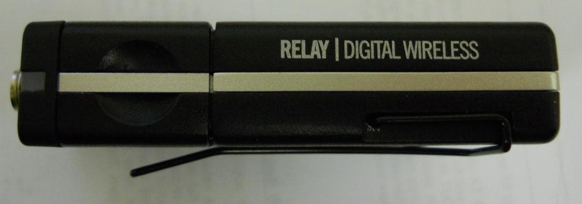
UOBTB516
Mar 03, 2015Hybrid Transmitter Wireless Guitar System
Equipment Class
DTS - Digital Transmission System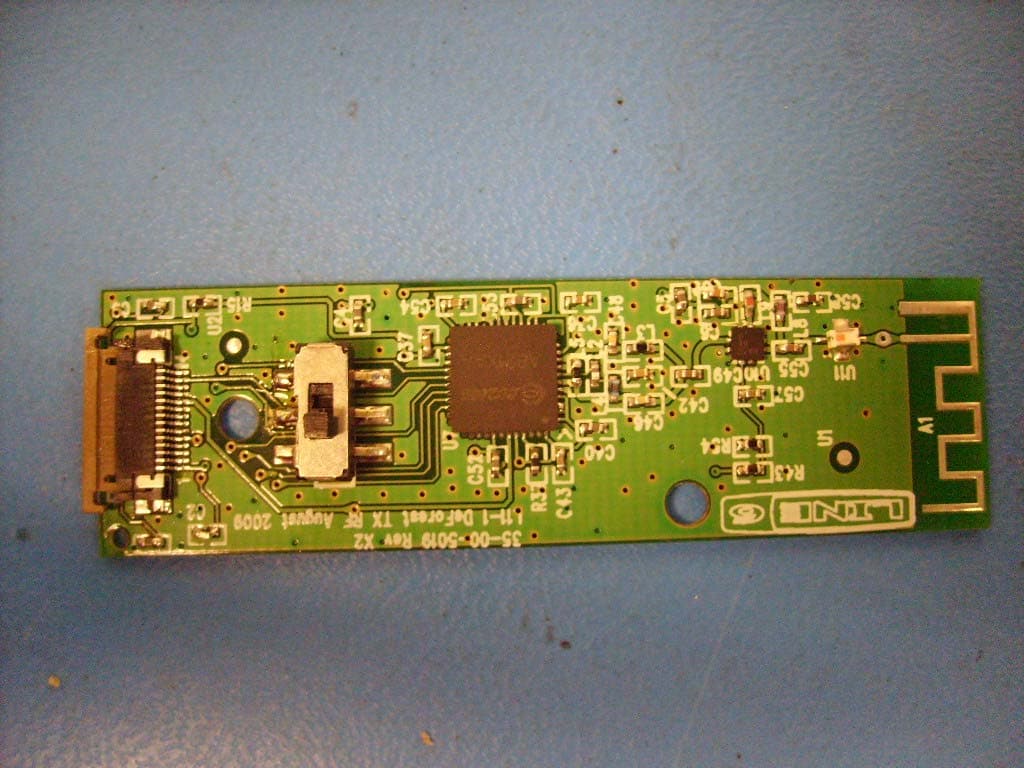
UOB916THH12
Dec 29, 20092.4 GHz Wireless handheld Microphone
Equipment Class
DTS - Digital Transmission System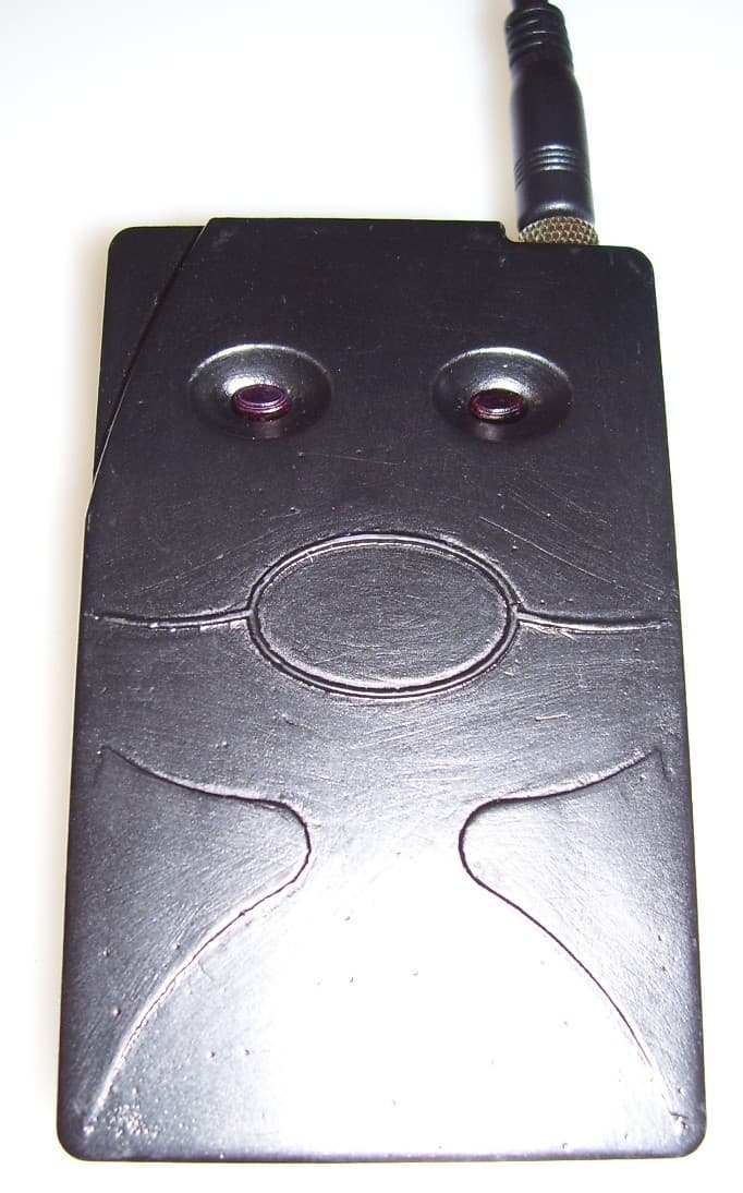
UOB91699TX95
Oct 30, 2006900MHz ISM Band Digital Audio Transmitter
Equipment Class
DTS - Digital Transmission System