UOB91699TX95900MHz ISM Band Digital Audio Transmitter
Line 6 Digital Wireless Inc.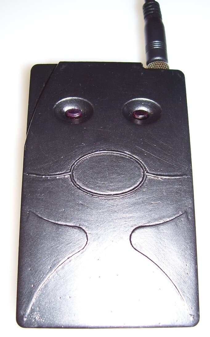
Click to zoom
Application Details
- Equipment Class
- DTS - Digital Transmission System
- Date of Grant
- Oct 30, 2006
- Application Purpose
- Original Equipment
- Date of Application
- Oct 30, 2006
- Equipment Note
- 900MHz ISM Band Digital Audio Transmitter
- Frequency Range
- 905.00000000 - 925.00000000
- Company
- Line 6 Digital Wireless Inc.
- Country
- United States
Documents & Files
Document Text
Text extracted from the exhibit documents filed with the FCC. Open a document above to read the original.
Users Manual
P L E A S E R E C O R D U N I TS E R I A LN U M B E R I N D I C AT E D O N T H E R E A R PA N E LF O R F U T U R E R E F E R E N C E Digital UHF Wireless System Model XDS95 Users Guide Includes easy setup instructions for single and multi-system operation Serial No: Digital Wireless Systems Created specifically for performing and recording musicians who demand to be untethered without compromising their sound, the XDS95 24-bit digi- tal wireless system delivers your tone and performance with the sound and feel of a direct wire connection. X2's proprietary digital technology provides superior fidelity while the XDS95’s "stomp-box" style receiver houses a micro-processor that selects the digital data stream from among the four internally mounted Q-diversity™ antennas to eliminate dropouts and interference including DTV. You’ll enjoy the sound and performance of a direct wire connection free from compander ICs and the associated 'pumping' and 'breathing' that squashes your tone, and other problems associated with analog wireless technology. Operating the system is unlike any wireless you've tried before. Simply connect the transmitter to the source via the 1/8" threaded-collar locking connector and the "stomp-box" style receiver to your amplifier, mixer or pedal-board. Then power up making sure the transmitter and receiver are set to the same channel. That's it. You're ready to go! No knobs to adjust and no antennas to loose or break mean you're up and running in the time it would take to connect a cable. About the XDS95 Digital Wireless System All of this sound and performance is provided to you with an incredible feature set including: • 24-bit digital converters yield 117 dB dynamic range to capture your most expressive performances • Frequency Clear™ UHF Digital - a proprietary digital signal on a 900 MHz UHF carrier for freedom from multipathing and interference, including DTV • Five user-selectable channels (all five are fully compatible for simultaneous use) • Auto-DigiScan™ to confidently select an open channel • Frequency response all the way down to 20 Hz for truly thundering lows • Stereo 1/4" output for instrument and full-bandwidth or 'tuner out' applications • Five segment LED display (battery status, link status, audio level, RF level and channel) With the XDS95 Digital UHF Wireless System you'll have the freedom and sound to deliver your most expressive performance every time without any hassles or complicated setup procedures. To familiarize you with your new digital wireless system, we suggest that you read through this entire operation manual. System Components System includes: • XDR1 Digital UHF Receiver • XDT1 Digital UHF Transmitter • 2 9v Alkaline Batteries • 1/4” to 1/8” locking connector instrument cable Optional Accessories: • Power supply for XDR1 Introduction to the XDS95 Digital UHF Wireless 2 LED Display • See system setup on page 5. 1/4” Mono/Stereo Output • See system setup on page 5. Power Switch • Press once to turn the power to the receiver on, and once more to turn the power off. 3 5 1 AC Adapter Jack (Adapter is optional) • 9V 300mA Mode/Channel Select Button • See system setup on page 5. 9V Battery Compartment • Battery compartment is secured with two screws. 4 2 1 XDS95 Digital UHF System Features 5 2 XDR1 Digital UHF Receiver XDT1 Digital UHF Transmitter 6 6 4 3 3 1 2 4 LED Display • See system setup on page 4. Power Switch • Press once to turn the power to the transmitter on, and once more to turn the power off. 1/8” Mono Instrument Input (cable included) • 1/4” to 1/8” locking connector. Mode/Channel Select Button • See system setup on page 4. Metal Belt Clip • Fastens transmitter securely to belt or guitar strap. 9V Battery Compartment • Battery compartement snaps in to place. 2 5 5 6 4 6 3 3 1 Power Up Procedure Press on/off button to turn unit on. LEDs will cycle blue-red-blue on power up sequence.Once unit is powered on the unit will display current channel number with a blue LED and battery life with a red led by continuously toggling between the two LEDs. As the user inputs audio into the unit the LEDs automatically become an audio level indictor where blue LEDs are displayed from left to right as the audio level increases. LED #5 will light red during audio display if the units input reaches a maximum level. After a few seconds pause in audio input the unit switches back to channel/battery display mode. Channel Selection There are 5 different frequency channels which you can choose to transmit and receive data, they are labeled 1-5 on both transmitter and receiver. In order to operate on any one of these channels, you must have both the transmitter and receiver on the same channel number. In order to change the transmit frequency push the channel button, the unit will then increment and display the channel number with a blue LED each time the user presses the button down. Continue this until the desired channel number is reached. The unit will then go back to the toggling LED mode to display battery life and channel number. Transmitter Battery Metering The battery is displayed on the tranmitter as follows: LED #5 (furthest to the right looking at the front of the unit) means 5hrs or greater of battery life remaining. As the battery expires the unit will change the red leds to #4 for 4hrs, #3 for 3hrs, etc.. Once the unit has less than 1hr left of battery life the #1 LED will then blink at a high rate until the battery expires. This alerts the user to the need of battery replacement. Power Down Procedure To turn the unit off press and hold the on/off switch until the LEDs flash a red/blue alternating pattern then release the on/off button. The unit will then power down. all LEDs off indicate power down is complete. Connecting the System Plug your instrument into the transmitter with the provided cable. Next, connect the output of the receiver to the input of your effects pedal, amplifier, recording device, etc.. When using a standard 1/4” (mon…
Text truncated - open the document above for the full version.
Attestation Statements
1 Jennifer Sanchez From: Marie Confroy Sent: Tuesday, October 31, 2006 7:07 AM To: Liming Xu; Jennifer Sanchez Cc: Tony Permsombut; Jennifer Sanchez; Shawn McMillen Subject: RE: 20866 - X2 Digital Wireless - METrak Mail From: Jennifer Sanchez Importance: High Attachments: Test Set Up Photographs.pdf; Transmitter External Photographs.pdf; Transmitter Internal Photographs.pdf; Receiver External Photographs.pdf; Receiver Internal Photographs.pdf Test Set Up Photographs.pdf (4.. Transmitter External Photograp.. Transmitter Internal Photograp... Receiver External Photographs.... Receiver Internal Photographs.... Liming, Attached please find the following: Receiver Internal and External photographs, the Transmitter External and Internal Photographs, and the Test Set-up Photographs for this application. I have updated the network, and have included all these files in both the FCC TCB and the Industry Canada CB Customer Information folder for this job. Please let Jennifer know what else you need. Thanks! Best Regards, Marie Ann Confroy Quality and Certifications Administrator MET Laboratories (410) 949-1910 [email protected] -----Original Message----- From: Liming Xu Sent: Monday, October 30, 2006 4:59 PM To: Jennifer Sanchez Cc: Tony Permsombut; Jennifer Sanchez; Marie Confroy; Shawn McMillen Subject: RE: 20866 - X2 Digital Wireless - METrak Mail From: Jennifer Sanchez Hi Jennifer, I can not find the internal and external photo Can you help me? I tried to find the antenna structure for IC BR Liming -----Original Message----- From: Jennifer Sanchez [mailto:[email protected]] Sent: Thursday, October 26, 2006 6:11 PM To: Liming Xu Cc: Tony Permsombut; Jennifer Sanchez; Marie Confroy; Shawn McMillen Subject: 20866 - X2 Digital Wireless - METrak Mail From: Jennifer Sanchez Importance: High Job Number: 20866 Model Desc: 900MHz ISM Band Digital Audio Transmitter Customer Name: X2 Digital Wireless Customer Code: X2D ----------------------------------------------------- Task Number: 313393 Task Description: EMC/TCB Application 2 Task Status: In Progress Hi Liming, Please accomplish technical review for the FCC TCB &, IC CB this project with the following information: H:\METrak_Job_Folders\2006\X\X2 Digital Wireless - X2D\20866\TCB\Customer Info H:\METrak_Job_Folders\2006\X\X2 Digital Wireless - X2D\20866\TCB\Customer Info\IC CB Please keep in mind that our turn around time for technical review is twenty-four to forty-eight hours. Let me know if I should provide you anything else, or if there may be any delays you may foresee in reviewing. Thanks! Best Regards, Jennifer Sanchez TCB Administrator/Technical Writer MET Laboratories Santa Clara, CA 510-489-6300 ext 612 http://www.metlabs.com 1 Jennifer Sanchez From: Shawn McMillen Sent: Monday, October 30, 2006 2:00 PM To: Liming Xu; Jennifer Sanchez Cc: Tony Permsombut; Jennifer Sanchez; Marie Confroy Subject: RE: 20866 - X2 Digital Wireless - METrak Mail From: Jennifer Sanchez Hi Liming. Jennifer is out on Mondays. On Tuesday she can get you the photos. The antenna is a PCB trace so there is no data sheet if that is what you are looking for. Shawn McMillen Regulatory Compliance MET Labs Santa Clara, CA 95054 408-919-0587 -----Original Message----- From: Liming Xu Sent: Monday, October 30, 2006 1:59 PM To: Jennifer Sanchez Cc: Tony Permsombut; Jennifer Sanchez; Marie Confroy; Shawn McMillen Subject: RE: 20866 - X2 Digital Wireless - METrak Mail From: Jennifer Sanchez Hi Jennifer, I can not find the internal and external photo Can you help me? I tried to find the antenna structure for IC BR Liming -----Original Message----- From: Jennifer Sanchez [mailto:[email protected]] Sent: Thursday, October 26, 2006 6:11 PM To: Liming Xu Cc: Tony Permsombut; Jennifer Sanchez; Marie Confroy; Shawn McMillen Subject: 20866 - X2 Digital Wireless - METrak Mail From: Jennifer Sanchez Importance: High Job Number: 20866 Model Desc: 900MHz ISM Band Digital Audio Transmitter Customer Name: X2 Digital Wireless Customer Code: X2D ----------------------------------------------------- Task Number: 313393 Task Description: EMC/TCB Application Task Status: In Progress Hi Liming, Please accomplish technical review for the FCC TCB &, IC CB this project with the following information: H:\METrak_Job_Folders\2006\X\X2 Digital Wireless - X2D\20866\TCB\Customer Info H:\METrak_Job_Folders\2006\X\X2 Digital Wireless - X2D\20866\TCB\Customer Info\IC CB Please keep in mind that our turn around time for technical review is twenty-four to forty-eight hours. Let me know if I should provide you anything else, or if there may be any delays you may foresee in reviewing. Thanks! 2 Best Regards, Jennifer Sanchez TCB Administrator/Technical Writer MET Laboratories Santa Clara, CA 510-489-6300 ext 612 http://www.metlabs.com
Block Diagram
4630 Beloit Dr. Suite 20, Sacramento, CA 95838 916-779-1040ph 916-779-1041fx Digital Wireless Systems Inc. October 4, 2006 MET Laboratories Inc. 914 West Patapsco Ave. Baltimore, MD 21230 RE: LETTER OF AGENT AUTHORIZATION To whom it may concern, We, the undersigned, hereby authorize MET Laboratories, Inc. to act on our behalf in all matters relating to application for equipment authorization, including the signing of all documents relating to these matters. We also hereby certify that no party to the application authorized hereunder is subject to the denial of benefits, including FCC benefits, pursuant to Section 5301 of the Anti-Drug Abuse Act of 1988, 21 U.S.C.853(a). This agreement expires one year from the current date. Sincerely, Guy Coker President X2 Digital Wireless Systems Inc. www.x2digitalwireless.com
Cover Letter(s)
4630 Beloit Dr. Suite 20, Sacramento, CA 95838 916-779-1040ph 916-779-1041fx Digital Wireless Systems Inc. October 5, 2006 MET Laboratories, Inc 914 West Patapsco Ave Baltimore, MD 21230 RE: Confidentiality Request for XDT1 Transmitter FCC ID UOB91699TX95 To Whom It May Concern: This letter serves as an official request for confidentiality under FCC Rule Section 0.459. We have requested that the schematic diagrams for the XDT1 Transmitter and XDR1 Receiver required to be submitted with this application be withheld from public review. This application contains detailed block diagrams, schematic diagrams, and a detailed theory of operation submitted to the FCC for review. The information within this application contains propriety information (trade secrets) regarding the circuit operation and capabilities specific values of components, circuit design and system architecture which are the results of our extensive investment in research and development. Without the disclosed information, competitive organizations would take considerable more time to asses and develop a workable competitive product. Since this is a new product in an existing market, we believe that is these documents are disclosed to our competitors, it would harm our ability to compete in this market. We therefore formally request that the materials contained in this envelope be kept strictly confidential and not made available for inspection by another party, except on a need to know basis for the sole purpose of the certification process. If you have any I may be reached at 916- 779-1040. Sincerely, Guy Coker President X2 Digital Wireless Systems Inc. www.x2digitalwireless.com
ID Label/Location Info
FCC ID: UOB91699TX95 IC: 6768A-91699TX 1.25 in 0.5 in FCC ID: UOB91699TX95 IC: 6768A-91699TX silkscreen on inset area
RF Exposure Info
X2 Digital Wireless Transmitter XDT1 CFR Title 47, Part 15, Subpart C MET Report: EMCS20866-FCC247 © 2006, MET Laboratories, Inc. Electromagnetic Compatibility Criteria for Intentional Radiators § 15.247(b) Peak Power Output and RF Exposure RF Exposure Requirements: §1.1307(b)(1) and §1.1307(b)(2): Systems operating under the provisions of this section shall be operated in a manner that ensures that the public is not exposed to radio frequency energy levels in excess of the Commission’s guidelines. RF Radiation Exposure Limit: §1.1310: As specified in this section, the Maximum Permissible Exposure (MPE) Limit shall be used to evaluate the environmental impact of human exposure to radiofrequency (RF) radiation as specified in Sec. 1.1307(b), except in the case of portable devices which shall be evaluated according to the provisions of Sec. 2.1093 of this chapter. MPE Limit Calculation: EUT’s operating frequencies @ 902-928 MHz ; highest conducted power = 10.03dBm (peak) therefore, Limit for Uncontrolled exposure: 0.6 mW/cm 2 or 6 W/m 2 EUT maximum antenna gain = -12 dBi. Equation from page 18 of OET 65, Edition 97-01 S = PG / 4πR 2 or R = √PG / 4πS where, P = Power Input to antenna (10.06mW) G = Antenna Gain (0.063 numeric) S = 10.06*0.063/ (4*3.14*20.0 2 ) = (0.633 / 5024) = 0.00125 mW/cm 2
Test Report
MET Laboratories, Inc. Safety Certification - EMI - Telecom Environmental Simulation 33439 WESTERN AVENUE ! UNION CITY, CALIFORNIA 94587 ! PHONE (510) 489-6300 ! FAX (510) 489-6372 The Nation’s First Licensed Nationally Recognized Testing Laboratory October 11, 2006 X2 Digital Wireless 4630 Beloit Dr# 20 Sacramento, CA 95838 Dear Guy Coker, Enclosed is the Telecom test report for compliance testing of the X2 Digital Wireless, Transmitter XDT1 as tested to the requirements of Title 47 of the CFR, Ch. 1 (10-1-03 ed.), Part 15, Subpart C for Intentional Radiators. Thank you for using the services of MET Laboratories, Inc. If you have any questions regarding these results or if MET can be of further service to you, please feel free to contact me. Sincerely yours, MET LABORATORIES, INC. Jennifer Sanchez Documentation Department Reference: (\X2 Digital Wireless\EMCS20866-FCC247) Certificates and reports shall not be reproduced except in full, without the written permission of MET Laboratories, Inc. While use of the National Voluntary Laboratory Accreditation Program (NVLAP) letters or the NVLAP Logo, the Standards Council of Canada Logo, or the Nationally Recognized Testing Laboratory (NRTL) Letters in this report reflects MET Accreditation under these programs, these letters, logo, or statements do not claim product endorsement by NVLAP or any Agency of the U.S. Government. This letter of transmittal is not a part of the attached report. Electromagnetic Compatibility X2 Digital Wireless Cover Page Transmitter XDT1 CFR Title 47, Part 15, Subpart C Certificates and reports shall not be reproduced except in full, without the written permission of MET Laboratories, Inc. Electromagnetic Compatibility Criteria Test Report for the X2 Digital Wireless Model Transmitter XDT1 Verified under the FCC Certification Rules contained in Title 47 of the CFR, Part 15.247, Subpart C for Intentional Radiators MET Report: EMCS20866-FCC247 October 11, 2006 Prepared For: X2 Digital Wireless 4630 Beloit Dr# 20 Sacramento, CA 95838 Prepared By: MET Laboratories, Inc. 4855 Patrick Henry Dr., Building 6, Santa Clara, CA 95054 Electromagnetic Compatibility X2 Digital Wireless Cover Page Transmitter XDT1 CFR Title 47, Part 15, Subpart C MET Report: EMCS20866-FCC247 © 2006, MET Laboratories, Inc. Page iii of vii Electromagnetic Compatibility Criteria Test Report for the X2 Digital Wireless Model Transmitter XDT1 Tested Under the FCC Certification Rules contained in Title 47 of the CFR, Part 15.247, Subpart C for Intentional Radiators Shawn McMillen, Project Engineer Jennifer Sanchez Electromagnetic Compatibility Lab Documentation Department Engineering Statement: The measurements shown in this report were made in accordance with the procedures indicated, and the emissions from this equipment were found to be within the limits applicable. I assume full responsibility for the accuracy and completeness of these measurements, and for the qualifications of all persons taking them. It is further stated that upon the basis of the measurements made, the equipment tested is capable of operation in accordance with the requirements of Part 15.247, of the FCC Rules under normal use and maintenance. Tony Permsombut, Manager Electromagnetic Compatibility Lab Electromagnetic Compatibility X2 Digital Wireless Report Status Transmitter XDT1 CFR Title 47, Part 15, Subpart C MET Report: EMCS20866-FCC247 © 2006, MET Laboratories, Inc. Page iv of vii Report Status Sheet Revision Report Date Reason for Revision ∅ October 11, 2006 Initial Issue. Electromagnetic Compatibility X2 Digital Wireless Table of Contents Transmitter XDT1 CFR Title 47, Part 15, Subpart C MET Report: EMCS20866-FCC247 © 2006, MET Laboratories, Inc. Page v of vii Table of Contents I. Executive Summary .................................................................................................................................................1 A. Purpose of Test ...................................................................................................................................................2 B. Executive Summary ............................................................................................................................................2 II. Equipment Configuration .......................................................................................................................................3 A. Overview.............................................................................................................................................................4 B. References...........................................................................................................................................................5 C. Test Site ..............................................................................................................................................................6 D. Description of Test Sample.................................................................................................................................6 E. Equipment Configuration....................................................................................................................................8 F. Ports and Cabling Information ............................................................................................................................8 G. Mode of Operation..............................................................................................................................................8 H. Method of Monitoring EUT Operation ...............................................................................................................8 I. Modifications ......................................................................................................................................................8 a) Modifications to EUT.........................................................................…
Text truncated - open the document above for the full version.
Test Setup Photos
Electromagnetic Compatibility X2 Digital Wireless Intentional Radiators Transmitter XDT1 CFR Title 47, Part 15, Subpart C MET Report: EMCS20866-FCC247 © 2006, MET Laboratories, Inc. Page 19 of 34 Electromagnetic Compatibility Criteria for Intentional Radiators Photograph 2. Test Equipment and setup for various Radiated Measurements
Contact Information
Applicant
Guy Coker(President)
Test Firm
MET LaboratoriesAlvin Ilarina
Technical Specifications
| # | Rule Parts | Frequency Range | Power Output | Emission |
|---|---|---|---|---|
| 1 | 15C | 905 MHz - 925 MHz | 10.00 mW | 514KF2W |
Other Applications from Line 6 Digital Wireless Inc.
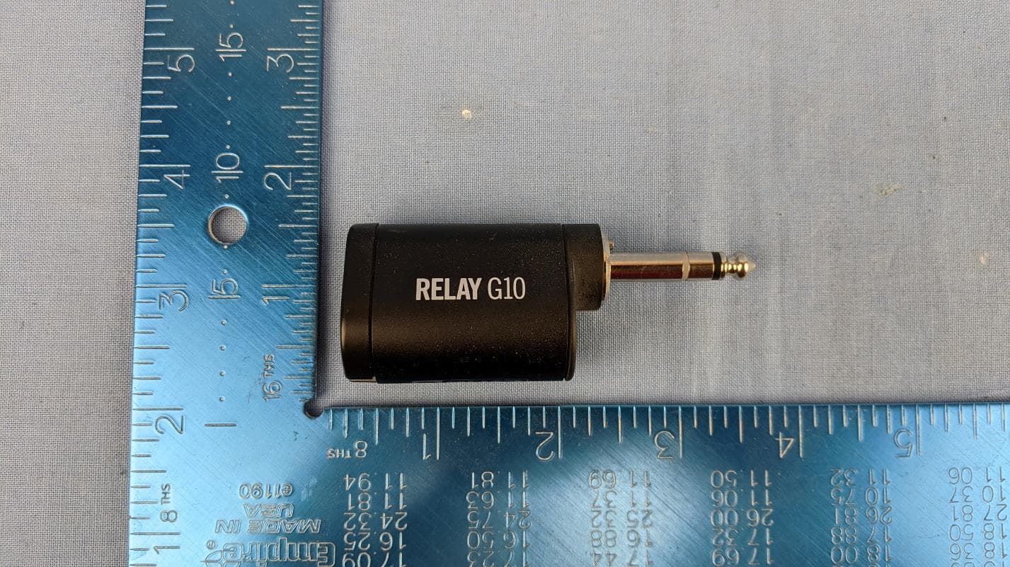
UOB-G10TII
Dec 03, 2020Wireless Transmitter
Equipment Class
DTS - Digital Transmission System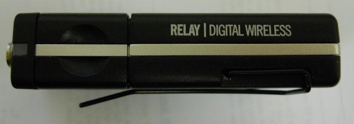
UOBTB516
Mar 03, 2015Hybrid Transmitter Wireless Guitar System
Equipment Class
DTS - Digital Transmission System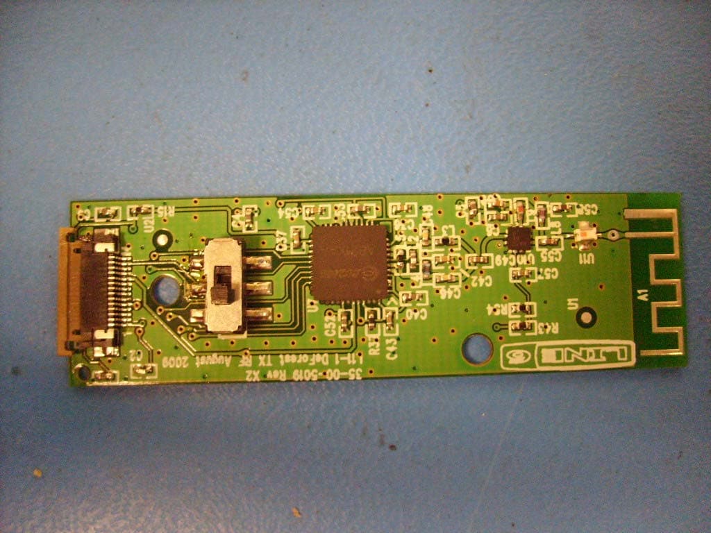
UOB916THH12
Dec 29, 20092.4 GHz Wireless handheld Microphone
Equipment Class
DTS - Digital Transmission System