UOBTB516Hybrid Transmitter Wireless Guitar System
Line 6 Digital Wireless Inc.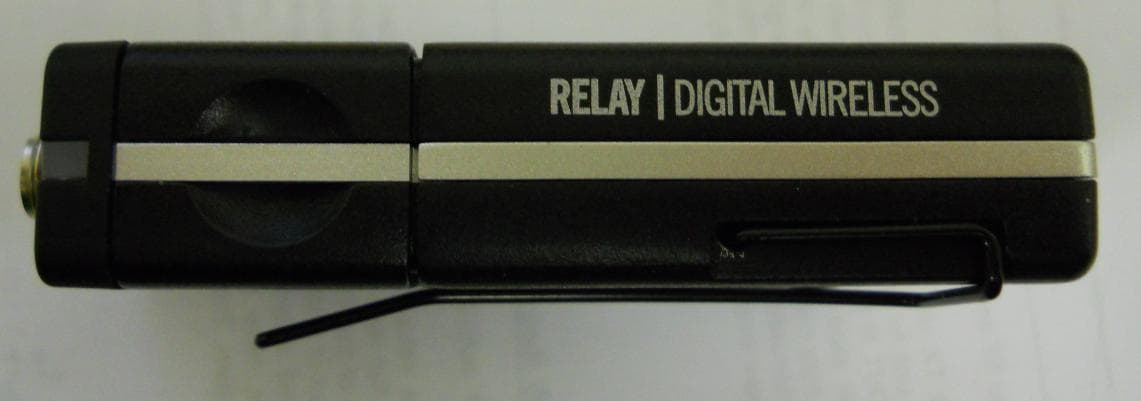
Click to zoom
Application Details
- Equipment Class
- DTS - Digital Transmission System
- Date of Grant
- Mar 03, 2015
- Application Purpose
- Original Equipment
- Date of Application
- Mar 03, 2015
- Equipment Note
- Hybrid Transmitter Wireless Guitar System
- Frequency Range
- 2401.50000000 - 2481.50000000
- Company
- Line 6 Digital Wireless Inc.
- Country
- United States
Documents & Files
Document Text
Text extracted from the exhibit documents filed with the FCC. Open a document above to read the original.
Users Manual
THIS PAGE FOR REFERNCE ONLY USE ARTWORK ON FOLLOWING PAGES Manual Quick Start Relay G70/75 Part 40-00-0366 Manual is 210 mm wide x 148 mm tall. Use quality sheets. Use Black Ink Print using compliant ink only. Released for Production 01/05/2014. 26580 Agoura Road Calabasas, CA 91302 USA voice (818) 575-3733 fax (818) 575-3601 Part Name/Number: Prepared by:Date: REVISIONS J. Lynn, S. FazioJan. 5, 2015 REVISION A A Specifications / Notes: 40-00-0366 A RELAY G70/G75 PILOT’S GUIDE MANUEL DE PILOTAGE PILOTENHANDBUCH PILOTENHANDBOEK MANUAL DEL PILOTO 取扱説明書 40-00-0366 A Pilot’s Guide also available at www.line6.com/manuals ©2015 Line 6, Inc. Important Safety Instructions WARNING : TO REDUCE THE RISK OF FIRE OR ELECTRIC SHOCK, DO NOT EXPOSE THE APPLIANCE TO RAIN OR MOISTURE. WARNING : TO REDUCE THE RISK OF FIRE OR ELECTRIC SHOCK, DO NOT REMOVE SCREWS. NO USER-SERVICEABLE PARTS INSIDE. REFER SERVICING TO QUALIFIED SERVICE PERSONNEL. CAUTION RISK OF ELECTRIC SHOCK DO NOT OPEN SERIAL NO: Radio Approvals: FCC Part 15.27, FCC Part 15 B, RSS-210 (Canada), RSS-310 (Canada), EN 300 400 (Europe), EN 301.489 (Europe), Japan Radio 2.4GHz Band (Japan), VCCI Digital Device Class B (Japan), CISPR 22 (Australia and New Zealand). Certified under FCC Part 15. The CE declaration of Conformity can be obtained at http://line6.com/compliance/ CERTIFICATION THIS DEVICE COMPLIES WITH PART 15 OF THE FCC RULES. OPERATION IS SUBJECT TO THE FOLLOWING TWO CONDITIONS: (1) THIS DEVICE MAY NOT CAUSE HARMFUL INTERFERENCE, AND (2) THIS DEVICE MUST ACCEPT ANY INTERFERENCE RECEIVED, INCLUDING INTERFERENCE THAT MAY CAUSE UNDESIRED OPERATION. Warning: Changes or modifications not expressly approved in writing by Line 6 may void the users authority to operate this equipment. RF Exposure Statement: This transmitter must not be co-located or operated in conjunction with any other antenna or transmitter. Note: This equipment has been tested and found to comply with the limits for a Class B digital device, pursuant to part 15 of the FCC Rules. These limits are designed to provide reasonable protection against harmful interference in a residential installation. This equipment generates, uses and can radiate radio frequency energy and, if not installed and used in accordance with the instructions, may cause harmful interference to radio communications. However, there is no guarantee that interference will not occur in a particular installation. If this equipment does cause harmful interference to radio or television reception, which can be determined by turning the equipment off and on, the user is encouraged to try to correct the interference by one or more of the following measures: - Reorient or relocate the receiving antenna. - Increase the separation between the equipment and receiver. - Connect the equipment into an outlet on a circuit different from that to which the receiver is connected. - Consult the dealer or an experienced radio/TV technician for help. This Class B digital apparatus complies with Canadian ICES-003. Cet appareil numerique de la classe B est conforme a la norme NMB-003 du Canada. You should read these Important Safety Instructions. Keep these instructions in a safe place Before using your Relay G70/G75 Digital Wireless System, carefully read the applicable items of these operating instructions and the safety suggestions. 1. Obey all warnings in the Relay G70/G75 manual. 2. Do not perform service operations beyond those described in the Relay G70/G75 Manual. Service is required when the apparatus has been damaged in any way, such as: • Liquid has been spilled or objects have fallen into the apparatus • The unit has been exposed to rain or moisture • The unit does not operate normally or changes in performance in a significant way • The unit is dropped or the enclosure is damaged 3. Do not place near heat sources, such as radiators, heat registers, or appliances which produce heat. 4. Guard against objects or liquids entering the device. Do not use or place unit near water. 5. Do not step on cords. Do not place items on top of cords so that they are pinched or leaned on. Pay particular attention to the cord at the plug end and the point where it connects to the device. 6. Clean only with a damp cloth. 7. Only use attachments/accessories specified by the manufacturer. 8. Prolonged listening at high volume levels may cause irreparable hearing loss and/or damage. Always be sure to practice “safe listening.” System Overview • Best in class sound quality provided by: • 24 bit / 48kHz uncompressed digital transmission • Best in class DAC and ADC provide super low noise transmission (better than 120dB dynamic range) • Breakthrough low latency (< 1.5ms from analog input to analog output) nearly instant response between your fingers and your ears. • Advanced wireless technology: Line 6 has been providing guitarists with the most advanced digital wireless systems for years, culminating with this 5th generation design. • Built-in calibrated, quad-antenna array with advanced dual receiver topology • ¼" Locking jack input on bodypack - uses the locking plug provided or any 1/4” guitar plug you like • A receiver designed to accommodate multiple guitar transmitters where switching is as simple as stepping on a footswitch (G70) or pressing a front panel button (G75). Note: G75 supports optional remote footswitch as well. • Choice of compact stomp box or amp-top style receiver, for the utmost flexibility in cable routing and access to the user interface • Two selectable ¼" guitar outputs with configurable on/off, gain, and cable tone per guitar or scene • Additional dedicated ¼" “always on” output jack for direct connection to external tuners • A breakthrough configurable XLR direct output > 120 dB dynamic range, 24 bit accuracy audio performance and wireless freedom • ¼” Auxiliary input jack on the receiver to connect a wired guitar for ultimate performance flexibility • Use alkaline (provided) or rechargeable AA batteries (avail…
Text truncated - open the document above for the full version.
Cover Letter(s)
4960 Del Mar Ave Suite 10, Rocklin, CA 9577 818-575-6000ph 916-625-0885fx February 25, 2015 MET Laboratories, Inc 914 West Patapsco Ave Baltimore, MD 21230 RE: Confidentiality Request for TB516 & RS516 Also known as RELAY ™ G70 Wireless Guitar System FCC ID UOBTB516 To Whom It May Concern: This letter serves as an official request for confidentiality under section 0.457 and 0.459 of CFR 47. We have requested that the following documents for the ™ G70 Wireless Guitar System submitted with this application be withheld from public review. Schematics Block Diagram Operational Description This application contains detailed block diagrams, schematic diagrams, and a detailed theory of operation submitted to the IC for review. The information within this application contains propriety information (trade secrets) regarding the circuit operation and capabilities specific values of components, circuit design and system architecture which are the results of our extensive investment in research and development. Without the disclosed information, competitive organizations would take considerable more time to asses and develop a workable competitive product. Since this is a new product in an existing market, we believe that is these documents are disclosed to our competitors, it would harm our ability to compete in this market. We therefore formally request that the materials contained in this envelope be kept strictly confidential and not made available for inspection by another party, except on a need to know basis for the sole purpose of the certification process. If you have any I may be reached at 818- 575-3980 Sincerely, Michealle Coker Wireless Compliance & Project Administrator Line 6 Inc 4960 Del Mar Ave Suite 10, Rocklin, CA 9577 818-575-6000ph 916-625-0885fx
Cover Letter(s)
4960 Del Mar Ave Suite 10, Rocklin, CA 9577 818-575-6000ph 916-625-0885fx February 25, 2015 MET Laboratories, Inc 914 West Patapsco Ave Baltimore, MD 21230 RE: Confidentiality Request for TB516 & RT516 Also known as RELAY ™ G75 Wireless Guitar System FCC ID UOBTB516 To Whom It May Concern: This letter serves as an official request for confidentiality under section 0.457 and 0.459 of CFR 47. We have requested that the following documents for the ™ G75 Wireless Guitar Systems submitted with this application be withheld from public review. Schematics Block Diagram Operational Description This application contains detailed block diagrams, schematic diagrams, and a detailed theory of operation submitted to the IC for review. The information within this application contains propriety information (trade secrets) regarding the circuit operation and capabilities specific values of components, circuit design and system architecture which are the results of our extensive investment in research and development. Without the disclosed information, competitive organizations would take considerable more time to asses and develop a workable competitive product. Since this is a new product in an existing market, we believe that is these documents are disclosed to our competitors, it would harm our ability to compete in this market. We therefore formally request that the materials contained in this envelope be kept strictly confidential and not made available for inspection by another party, except on a need to know basis for the sole purpose of the certification process. If you have any I may be reached at 818- 575-3980 Sincerely, Michealle Coker Wireless Compliance & Project Administrator Line 6 Inc 4960 Del Mar Ave Suite 10, Rocklin, CA 9577 818-575-6000ph 916-625-0885fx
External Photos
Company Confidential Confidential TBP516 Document ID: TB516 Prepared By: M Coker TB516 External Photo’s TOP BACK Company Confidential Confidential TBP516 SIDE LEFT SIDE RIGHT Company Confidential Confidential TBP516 TOP BOTTOM
Internal Photos
Company Confidential Confidential TBP516 Document ID: TB516 Prepared By: M Coker TB516 Internal Photo’s RF PCBA RF PCBA Company Confidential Confidential TBP516 RF PCBA RF PCB Company Confidential Confidential TBP516 RF PCB Company Confidential Confidential TBP516 MAIN PCBA MAIN PCBA Company Confidential Confidential TBP516 MAIN PCBA UI PCB
RF Exposure Info
Figure 1 1.5dBi Ref 2400-2485MHz sweep Figure 2 1.5dBi Ref 2400-2485MHz sweep Figure 3 1.5dBi Ref 2400-2485MHz sweep Figure 4 1.5dBi Ref 2400-2485MHz sweep Figure 5 1.5dBi Ref 2400-2485MHz sweep Figure 6 1.5dBi Ref 2400-2485MHz sweep
RF Exposure Info
§ 15.247(i) Maximum Permissible Exposure RF Exposure Requirements: §1.1307(b)(1) and §1.1307(b)(2): Systems operating under the provisions of this section shall be operated in a manner that ensures that the public is not exposed to radio frequency energy levels in excess of the Commission’s guidelines. RF Radiation Exposure Limit: §1.1310: As specified in this section, the Maximum Permissible Exposure (MPE) Limit shall be used to evaluate the environmental impact of human exposure to radiofrequency (RF) radiation as specified in Sec. 1.1307(b), except in the case of portable devices which shall be evaluated according to the provisions of Sec. 2.1093 of this chapter. MPE Limit Calculation: EUT’s operating frequencies @ 2400-2483.5 MHz; highest conducted power = 16.18dBm (peak) therefore, Limit for Uncontrolled exposure: 1 mW/cm 2 or 10 W/m 2 EUT maximum antenna gain = 2 dBi (1.584 numeric) Equation from page 18 of OET 65, Edition 97-01 S = PG / 4R 2 or R = √PG / 4S where, P = Power Input to antenna = 8.73dBm (7.464 mW) G = Antenna Gain = 2dBi (1.584 numeric) R = Minimum Distance between User and Antenna (20cm) S = (7.464*1.584)/(4*3.14*400 ) = 0.002 mW/cm2
Test Report
MET Laboratories, Inc. Safety Certification - EMI - Telecom Environmental Simulation 914 WEST PATAPSCO AVENUE • BALTIMORE, MARYLAND 21230-3432 • PHONE (410) 354-3300 • FAX (410) 354-3313 33439 WESTERN AVENUE • UNION CITY, CALIFORNIA 94587 • PHONE (510) 489-6300 • FAX (510) 489-6372 3162 BELICK STREET • SANTA CLARA, CA 95054 • PHONE (408) 748-3585 • FAX (510) 489-6372 13301 MCCALLEN PASS • AUSTIN, TEXAS 78753 • PHONE (512) 287-2500 • FAX (512) 287-2513 The Nation’s First Licensed Nationally Recognized Testing Laboratory March 4, 2015 Line 6 4095 Del Mar Ave # 10 Rocklin, CA 95677 Dear Michealle Coker, Enclosed is the EMC Wireless test report for compliance testing of the Line 6, TB516 Transmitter as tested to the requirements of Title 47 of the CFR, Ch. 1 (10-1-06 ed.), Part 15, Subpart C and RSS-210, Issue 8, Dec. 2010 for Intentional Radiators. Thank you for using the services of MET Laboratories, Inc. If you have any questions regarding these results or if MET can be of further service to you, please feel free to contact me. Sincerely yours, MET LABORATORIES, INC. Jennifer Warnell Documentation Department Reference: (\Line 6\EMCS84743-FCC247 Rev. 1) Certificates and reports shall not be reproduced except in full, without the written permission of MET Laboratories, Inc. Electromagnetic Compatibility Line 6 Cover Page TB516 Transmitter CFR Title 47, Part 15.247; RSS-210, Issue 8, Dec. 2010 MET Report: EMCS84743-FCC247 Rev. 1 © 2015, MET Laboratories, Inc. Page ii of vii DOC-EMC702 6/18/2009 Electromagnetic Compatibility Criteria Test Report for the Line 6 TB516 Transmitter Tested under the FCC Certification Rules contained in Title 47 of the CFR, Part 15.247 Subpart C & RSS-210, Issue 8, Dec. 2010 for Intentional Radiators MET Report: EMCS84743-FCC247 Rev. 1 March 4, 2015 Prepared For: Line 6 4095 Del Mar Ave # 10 Rocklin, CA 95677 Prepared By: MET Laboratories, Inc. 914 W. Patapsco Ave. Baltimore, MD 21230 Electromagnetic Compatibility Line 6 Cover Page TB516 Transmitter CFR Title 47, Part 15.247; RSS-210, Issue 8, Dec. 2010 MET Report: EMCS84743-FCC247 Rev. 1 © 2015, MET Laboratories, Inc. Page iii of vii DOC-EMC702 6/18/2009 Electromagnetic Compatibility Criteria Test Report for the Line 6 TB516 Transmitter Tested under the FCC Certification Rules contained in Title 47 of the CFR, Part 15.247 Subpart C & RSS-210, Issue 8, Dec. 2010 for Intentional Radiators Ajaz Khan, Project Engineer Jennifer Warnell Electromagnetic Compatibility Lab Documentation Department Engineering Statement: The measurements shown in this report were made in accordance with the procedures indicated, and the emissions from this equipment were found to be within the limits applicable. I assume full responsibility for the accuracy and completeness of these measurements, and for the qualifications of all persons taking them. It is further stated that upon the basis of the measurements made, the equipment tested is capable of operation in accordance with the requirements of the FCC Rules Part 15.247 and Industry Canada standard RSS-210, Issue 8, Dec. 2010 under normal use and maintenance. Asad Bajwa, Director, Electromagnetic Compatibility Lab Electromagnetic Compatibility Line 6 Report Status TB516 Transmitter CFR Title 47, Part 15.247; RSS-210, Issue 8, Dec. 2010 MET Report: EMCS84743-FCC247 Rev. 1 © 2015, MET Laboratories, Inc. Page iv of vii DOC-EMC702 6/18/2009 Report Status Sheet Revision Report Date Reason for Revision February 20, 2015 Initial Issue. 1 March 4, 2015 Editorial corrections. Electromagnetic Compatibility Line 6 Table of Contents TB516 Transmitter CFR Title 47, Part 15.247; RSS-210, Issue 8, Dec. 2010 MET Report: EMCS84743-FCC247 Rev. 1 © 2015, MET Laboratories, Inc. Page v of vii DOC-EMC702 6/18/2009 Table of Contents I. Executive Summary .................................................................................................................................................1 A. Purpose of Test ...................................................................................................................................................2 B. Executive Summary ............................................................................................................................................2 II. Equipment Configuration .......................................................................................................................................3 A. Overview .............................................................................................................................................................4 B. References ...........................................................................................................................................................5 C. Test Site ..............................................................................................................................................................5 D. Description of Test Sample .................................................................................................................................6 E. Equipment Configuration ....................................................................................................................................6 F. Support Equipment .............................................................................................................................................7 G. Mode of Operation ..............................................................................................................................................7 H. Method of Monitoring EUT Operation ...............................................................................................................7 I. Modifications ......................................................................................................................................................7 a) Modifications to EUT ...........................................…
Text truncated - open the document above for the full version.
Test Setup Photos
Photograph 1. Radiated Spurious Emissions, Test Setup, 1 Photograph 2. Radiated Spurious Emissions, Test Setup, 2
Contact Information
Applicant
Guy Coker(President)
Technical Contact
Line 6Guy Coker
[email protected]818-575-3981
4095 DelMar Ave # 10 · Rocklin, California · United States
Non-Technical Contact
Line 6Michealle Coker
[email protected]818-575-3980
Test Firm
MET Laboratories, Inc.Ram Shrestha
[email protected]4082874793
Technical Specifications
| # | Rule Parts | Frequency Range | Power Output |
|---|---|---|---|
| 1 | 15C | 2.40 GHz - 2.48 GHz | 7.46 mW |
Other Applications from Line 6 Digital Wireless Inc.
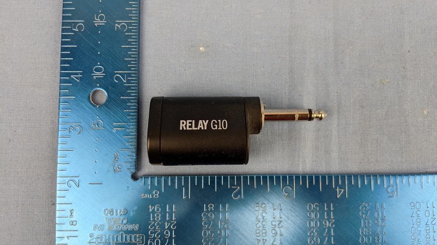
UOB-G10TII
Dec 03, 2020Wireless Transmitter
Equipment Class
DTS - Digital Transmission System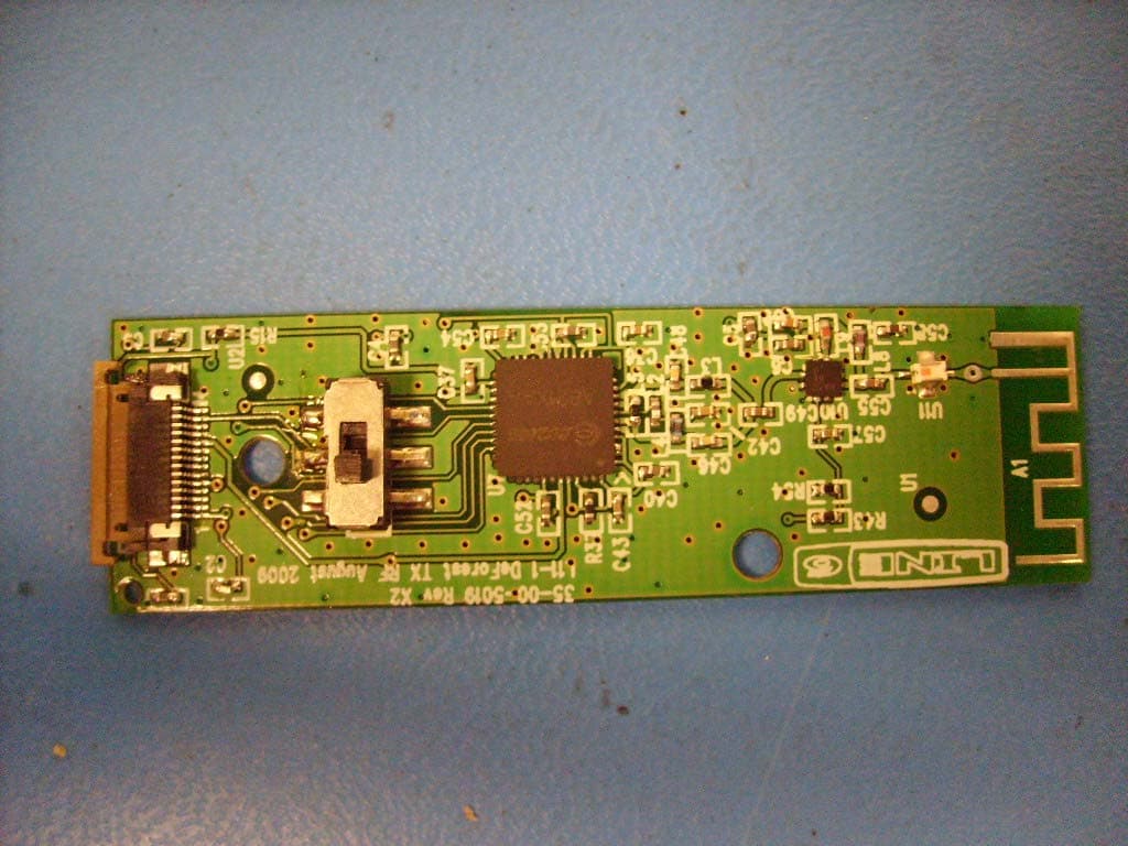
UOB916THH12
Dec 29, 20092.4 GHz Wireless handheld Microphone
Equipment Class
DTS - Digital Transmission System
UOB91699TX95
Oct 30, 2006900MHz ISM Band Digital Audio Transmitter
Equipment Class
DTS - Digital Transmission System