UOXALLIANCE24380CVS ALARM II- 433MHz TRANSMITTER
PICA Product Development
Click to zoom
Application Details
- Equipment Class
- DXX - Part 15 Low Power Communication Device Transmitter
- Date of Grant
- Nov 19, 2006
- Application Purpose
- Original Equipment
- Date of Application
- Nov 16, 2006
- Equipment Note
- CVS ALARM II- 433MHz TRANSMITTER
- Frequency Range
- 433.54000000 - 434.54000000
- Company
- PICA Product Development
- Country
- United States
Documents & Files
Document Text
Text extracted from the exhibit documents filed with the FCC. Open a document above to read the original.
Users Manual
Theft Deterrent System Electronics Package Receiver & Transmitter User Manual PLEASE LEAVE THIS MANUAL WITH THE STORE MANAGER Index: Introduction ........................................................................................................................ Receiver Instructions........................................................................................................ Summary .................................................................................................................... Front Panel ................................................................................................................ Rear Panel ...................................................................................................................... Bottom Panel ............................................................................................................. Message Formatting .................................................................................................... Message Encryption ...................................................................................................... Install Summary ................................................................................................ Operation & Programming ................................................................................ Specifications ............................................................................................................ Transmitter Instructions....................................................................................................... Summary & Operation ................................................................................................. Top View ..................................................................................................................... Back View (Battery Replacement) ............................................................................... Install Summary .......................................................................................................... Specifications .............................................................................................................. Cable Harness Diagram ............................................................................................. Message Select Chart ............................................................................................................. Warranty & FCC ...................................................................................................................... 3 Store Manager Note: If unit needs support or service do the following: Go online to www.alliance-cvs.com and check for the most common support questions. User: manager Password: razor If your question is not answered or resolved then, Call 1-866-594-7762 for assistance. 4 5 5 5 6 7 8 8 9 11 12 13 13 13 15 16 17 17 18 27 Introduction: The Alliance Theft Deterrent / In-Store Messaging System consists of two distinct parts – the mechanical pack- age (that includes the display fixture and cabinet) and the electronics package (that includes the transmitter and receiver modules). This kit users guide covers the electronics package only - if you are having support issues with the cabinet then please refer to the users guide for the cabinet fixture. 4 Mechanical Package Electronics Package Transmitter Receiver 5 Receiver Instructions: Summary: The Receiver/Message Repeater Module is a state-of-the-art digital audio playback device with a 433MHz RF receiver designed to provide up to 255 audio messages that can be activated and played over a stores public announcement system. Messages are activated by either receiving triggering information from remote transmitters and/or by a built-in timer that will play messages on specific time intervals. Messages are stored as encrypted MP3 files on industry standard USB flash drives from 16MB up to 4GB with playback quality up to near CD-quality (128Kbps). Audio content is easily managed by plugging the USB flash drive into a PC or MAC computer’s USB port and “dragging and dropping” encrypted MP3 files to and from the drive. Managers can receive new and updated messages via e-mail or ftp and update the units themselves. Files are encrypted using Sonocrypt Level 3 technology. Sonocrypt encrypts the file itself making the MP3 file unplayable anywhere except on the unit. This makes the distribution of messaging safe, secure, and ensures against unauthorized playback. Front Panel: SPEAKER - The SPEAKER switch can be turned ON and OFF to monitor audio and will have no effect on the audio playing on the sales floor. Switch should normally be kept OFF. STATUS - The STATUS indicator is a LED that during normal operation with a USB drive inserted in to the unit will be solid blue. If there is a problem with the USB drive; files are not encrypted, drive is not inserted or is empty this LED will blink blue. USB PLUG - The USB drive is inserted here to play audio. If insertion of drive is difficult, make sure drive is oriented correctly. Drive should slide into jack smoothly. IMPORTANT: This unit WILL NOT play standard MP3 files! USB drives used on this playback device must be encrypted! Audio changes will be made by receiving a new USB drive by mail, e-mail or web site download. Rear Panel: 6 BGM IN 8Ω OUT 600Ω OUT POWER ON (1) OFF (0) ANT 12VDC ACTIVESTOP GND 500mA ACTIVE - This is an output circuit that outputs +12VDC @ 25mA maximum when a message is playing from the unit. If circuit is to exceed the 25mA rating then a relay is required to drive the higher load. The GND should be used as a return on the circuit. Exceeding 25mA will damage this circuit. Example Circuits: STOP - This is used to stop any messages that are playing or queued (stacked) on the unit. To use this circuit, short the STOP and GND connections together with either a push-button or switch. GND - This is used as a ground return on both the ACTIVE and S…
Text truncated - open the document above for the full version.
External Photos
External Photos: Nel Tech CVS Alarm II (transmitter) Front view: Rear View:
ID Label/Location Info
Nel-Tech Labs Mechanical Assembly Diagram Step 4 305-00002
ID Label/Location Info
CE Mark Industry Canada Registration Number Serial Number Model Number Trade Name TX XX XX XXXXXX Unit Number Week Year TX FCC ID FCC Statement Nel-Tech Labs Transmitter Serial # Specifications
Internal Photos
Interior Photos: Nel Tech CVS Alarm II Transmitter Front of board inside case: Front of board: Rear of board:
Test Report
Compliance Worldwide, Inc. - 357 Main Street - Sandown, NH 03873 (603) 887 3903 Fax 887 6445 http://www.complianceworldwide.com COMPLIANCE WORLDWIDE INC. TEST REPORT 287-06 In Accordance with the Requirements of Industry Canada RSS 210, Issue 6, Annex II Federal Communications Commission CFR Title 47 Part 15.231, Subpart C Low Power License-Exempt Radio Communication Devices Intentional Radiators Issued to Nel-Tech Labs 4 Ash Street Extension Derry, NH 03038 for CVS Alarm II 433 MHz Transmitter FCC ID: UOXALLIANCE24380 IC: 3358A-TXTYPE1 Report Issued on November 2, 2006 Prepared by This test report shall not be reproduced, except in full, without written permission from Compliance Worldwide, Inc. Test Number: 287-06 Issue Date: 11/02/2006 Page 2 of 13 Compliance Worldwide, Inc. - 357 Main Street - Sandown, NH 03873 (603) 887 3903 Fax 887 6445 http://www.cw-inc.com Table of Contents 1. Scope..................................................................................................................... 3 2. Product Details....................................................................................................... 3 3. Product Configuration ............................................................................................ 3 4 Measurements Parameters..................................................................................... 5 5 Measurement Summary.......................................................................................... 6 6 Measurement Data ................................................................................................. 6 7. Test Site Description.............................................................................................. 6 Test Number: 287-06 Issue Date: 11/02/2006 Page 3 of 13 Compliance Worldwide, Inc. - 357 Main Street - Sandown, NH 03873 (603) 887 3903 Fax 887 6445 http://www.cw-inc.com 1. Scope This test report certifies that the Nel Tech Labs, Inc. CVS Alarm II 433 MHz transmitter, as tested, meets the RSS 210 Annex II Rules and FCC Part 15.231, Subpart C requirements. The scope of this test report is limited to the test sample provided by the client, only in as much as that sample represents other production units. If any significant changes are made to the unit, the changes shall be evaluated and a retest may be required 2. Product Details 2.1. Manufacturer: Nel Tech Labs, Inc. 2.2. Model Number: Alliance 24380 2.3. Serial Number: TX064100315 2.4. Description: CVS Alarm II 433 MHz transmitter 2.5. Power Source: (3) AA Battery powered 2.6. EMC Modifications: R14 value was changed from 0 ohms to 1.5k ohms. 3. Product Configuration 3.1. Cables Cable Type Length Shield From To N/A 3.2. Support Equipment Device Manufacturer Model Serial No. CVS Multi Message Receiver Nel Tech Labs, Inc. Alliance 24380 TX064100315 3.3. Operational Characteristics N/A Test Number: 287-06 Issue Date: 11/02/2006 Page 4 of 13 Compliance Worldwide, Inc. - 357 Main Street - Sandown, NH 03873 (603) 887 3903 Fax 887 6445 http://www.cw-inc.com 3. Product Configuration (continued) 3.4. Block Diagram CVS Alarm II Transmitter EUT CVS Multi Message Receiver Speaker cable AC power Test Number: 287-06 Issue Date: 11/02/2006 Page 5 of 13 Compliance Worldwide, Inc. - 357 Main Street - Sandown, NH 03873 (603) 887 3903 Fax 887 6445 http://www.cw-inc.com 4 Measurements Parameters 4.1 Measurement Equipment Used to Perform Test Device ManufacturerModel No.Serial No.Last Cal Cal Due EMI Receiver Hewlett Packard 8546A 3650A00360 1/5/2005 1/5/2007 Spectrum Analyzer Hewlett Packard 8593E 3829A03887 3/13/2006 3/13/2007 Biconilog Antenna Com-Power AC220 25509 1/31/2006 1/31/2007 Horn Antenna Electro-Metrics EM-6961 6337 8/25/2006 8/25/2008 4.2 Measurement & Equipment Setup Test Date: 10/13/06 Test Engineer: Robert J. McCall Normal Site Temperature (15 - 35°C): 21.7 Extreme Test Temperatures (°C): 0 and +35 Relative Humidity (20 -75%RH): 32 Frequency Range: 418 MHz Measurement Distance: 3 Meters EMI Receiver IF Bandwidth: Depends on measurement EMI Receiver Avg Bandwidth: Depends on measurement Detector Function: Depends on measurement 4.3 Test Procedure Test measurements were made in accordance FCC Part 15.231: Operation within the bands 40.66 – 40.70 MHz and above 70 MHz. The test methods used to generate the data in this test report are in accordance with ANSI C63.4: 2003, American National Standard for Methods of Measurement of Radio- Noise Emissions from Low-Voltage Electrical and Electronic Equipment in the Range of 9 kHz to 40 GHz Test Number: 287-06 Issue Date: 11/02/2006 Page 6 of 13 Compliance Worldwide, Inc. - 357 Main Street - Sandown, NH 03873 (603) 887 3903 Fax 887 6445 http://www.cw-inc.com 5 Measurement Summary Test Requirement FCC Rule Requirement Test Report Section Result Comment Antenna Requirement 15.203 N.A Compliant Unit has a permanently mounted antenna. Radiated Field Strength of Fundamental 15.231 (b) 6.1 Compliant Radiated Field Strength of Harmonics 15.231 (a) 6.2 Compliant Occupied Bandwidth 6.3 Compliant Spurious Radiated Emissions 15.231 (b), 15.209 6.4 Compliant Conducted Emissions 15.207 N.A Compliant Unit is battery operated Test Number: 287-06 Issue Date: 11/02/2006 Page 7 of 13 Compliance Worldwide, Inc. - 357 Main Street - Sandown, NH 03873 (603) 887 3903 Fax 887 6445 http://www.cw-inc.com 6 Measurement Data 6.1 Radiated Field Strength of Fundamental (15.231, Section (b)) Requirement: The 3 meter field strength of the fundamental emissions from intentional radiators operated within the 260-470 MHz frequency bands shall comply with the limits specified in FCC Part 15.231, Section (b). Frequency (MHz) Amplitude (dBμV/m) Limit (dBμV/m) Margin (dB) Ant Pol Ant Ht TT Pos Result Peak Average H/V cm Deg P/F 433.94 86.7 78.980.82 -1.92 H 100 294 Passed Test Number: 287-06 Issue Date: 11/02/2006 Page 8 of 13 Compliance Worldwide, Inc. - 357 Main Street - Sandown, NH 03873 (603) 887 3903 Fax 887 6445 http://www.cw-inc.com …
Text truncated - open the document above for the full version.
Test Setup Photos
Test Set up Photos: Nel Tech CVS Alarm II 433 MHz Transmitter (report # 287-06) Radiated Front View: Radiated Rear view:
Contact Information
Applicant
Scott Stapleford(CTO)
Test Firm
Compliance Worldwide, Inc.Larry Stillings
Technical Specifications
| # | Rule Parts | Frequency Range | Power Output |
|---|---|---|---|
| 1 | 15C | 433.54 MHz - 434.54 MHz | - |
Other Applications from PICA Product Development
UOXSKYHAWKDUOSEN1
Dec 04, 2025Skyhawk Duo Sensor
Equipment Class
DTS - Digital Transmission System
UOXSKYHAWKVERSEN1
Dec 04, 2025Skyhawk Versa Sensor
Equipment Class
DSS - Part 15 Spread Spectrum TransmitterUOXSKYHAWKTRESEN2
Jun 18, 2023Vibration/Magnet sensors for remote monitoring of rodents/wildlife traps
Equipment Class
DSS - Part 15 Spread Spectrum Transmitter
UOXSKYHAWKMSESEN1
Mar 22, 2020Mouse Sensor/Transceiver
Equipment Class
DXX - Part 15 Low Power Communication Device Transmitter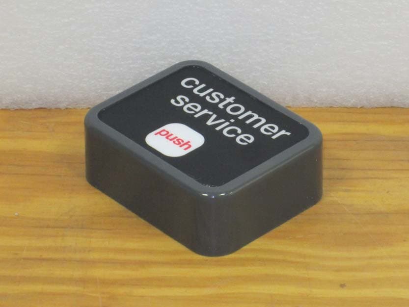
UOXNTLCSBUTTON
Nov 25, 2013434.0 MHz CUSTOMER SERVICE BUTTON
Equipment Class
DSC - Part 15 Security/Remote Control Transmitter