UOXNTLCSBUTTON434.0 MHz CUSTOMER SERVICE BUTTON
PICA Product Development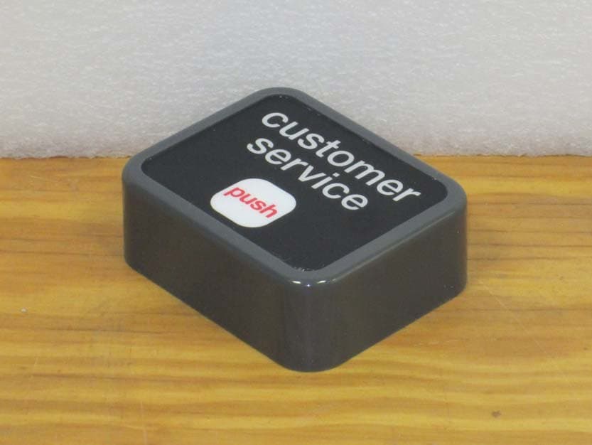
Click to zoom
Application Details
- Equipment Class
- DSC - Part 15 Security/Remote Control Transmitter
- Date of Grant
- Nov 25, 2013
- Application Purpose
- Original Equipment
- Date of Application
- Nov 25, 2013
- Equipment Note
- 434.0 MHz CUSTOMER SERVICE BUTTON
- Frequency Range
- 434.00000000 - 434.00000000
- Company
- PICA Product Development
- Country
- United States
Documents & Files
Document Text
Text extracted from the exhibit documents filed with the FCC. Open a document above to read the original.
Users Manual
Customer Service Button Part # 942143 On-Site Retail Installation Instructions For Installation Support Call 1-866-987-3343 Customer Service Button Parts Breakdown Fragrance/Cabinet Bracket Button Mount Shelf Bracket Customer Service Button #0 Phillips Long Screwdriver #2 Phillips Stubby Screwdriver Hardware Kit (3) #6 x 3/8" Truss Screws (Type A) (2) #4 x 5/16" Pan Head Screws (Type B) (4) #10-24 x 3/8" Truss Head Screws (2) #10 Split Lock Washers (2) #10 Wing Nuts AAA Battery Installation Instructions Fragrance Cabinet Glass Static Cling 2 Hardware Kit Breakdown #10-24 x 3/8"Truss Head Screw (Type A) #6 x 3/8" Truss Head Screw (Type B) #4 x 5/16" Pan Head Screw #10 Split Lock Washer #10 Wing Nuts 3 Customer Service Button Initial Setup Step 1: Remove the battery door from the rear of the button with the long screwdriver. Step 2: A single battery should already be removed, if not remove the battery closest to the hinge of the door. In the bottom of the battery cavity there will be a ten position DIP switch. This switch is used to set the frequency channel number and message number to be triggered when the button is pressed. DIP Switch Step 3: The DIP switch position marked 10 is used to set the buttons transmit frequency channel. Verify this matches the stores receiver frequency channel. If receiver frequency is unknown then start with Channel A since most stores are set this way. Channel A - DIP #10 is set to OFF Channel B - DIP #10 is set to ON 4 Step 4: DIP switch positions marked 1 through 8 are used to set the message that will play over the stores PA when the button is pressed. Use the Message DIP Switch Setting Chart (pages 11 -12) to set the message. The unit comes preset with the switches set to trigger the bilingual “Fragrance Case” message (see example below). Take notice of the “ON” direction of the switch - ON is UP towards the “ON” marking on the switch and OFF is DOWN towards the numbers on the switch. DIP switch 9 is not used. Example of “Fragrance Case” message slot #75 setting & Channel set to “A” Step 5: Insert the AAA battery into the cavity over the switch and secure down the door with the screw using the long screwdriver. Step 6: Press the button on the front of the button assembly to verify the correct message plays. If message does not play refer to the troubleshooting section of this manual. Press to Play Message Step 7: Move to the next section of the manual for the appropriate mounting type: Shelf Mount (page 6), Fragrance Case Mount (page 7 - 9) or Cabinet Mount (page 10). 5 Step 1: Attach customer service button mount to metal shelf bracket using two #10 x 3/8" phillips truss head screws with the stubby screwdriver. Step 2: Attach customer service button to the assembly from the above step using two #4 x 5/16" phillips pan head screws with the long screwdriver. Step 3: Attach the finished assembly to the shelf using a #10 x 3/8" phillips truss head screw, #10 lock washer and #10 wing nut. Shelf Mounting Instructions Step 4: Press the button on the front of the button assembly to verify the correct message plays. If message does not play refer to the troubleshooting section of this manual, otherwise installation is complete. Save the box, manual and unused hardware for future use. 6 Fragrance Display Mounting Instructions (Left Side) Step 1: Attach customer service button mount to metal cabinet/fragrance bracket using two #10 x 3/8" phillips truss head screws with the stubby screwdriver. Step 2: Attach customer service button to the assembly from the above step using two #4 x 5/16" phillips pan head screws with the long screwdriver. Step 3: Hold the completed assembly from the step above against the side of the fragrance cabinet and 44" from the floor to the center of the bracket. Slide the bracket back as far back as it will go without interfering with the operation of the door handle on the cabinet. Left side of cabinet Left glass door handle 44" Top View Verify door handle does not contact back of bracket. Slide back as far as it will go without interfering with door. to floor 7 Step 4: While still holing the button assembly mark the two larger holes on the cabinet. Step 5: Set button assembly aside and drill two 7/32" holes at the marked locations. Verify there are no obstructions or that the door channel will not be contacted when drilling these holes. Step 6: Attach the button assembly to the side of the fragrance cabinet using two #10 x 3/8" phillips truss head screws, #10 lock washers and #10 wing nuts with the stubby screwdriver. Note: For right side mounting flip button on bracket and drill holes on the right side of cabinet. 8 Step 9: Press the button on the front of the button assembly to verify the correct message plays. If message does not play refer to the troubleshooting section of this manual, otherwise installation is complete. Save the box, manual and unused hardware for future use. Step 7: Open the envelope labeled “STATIC CLING” and remove the labels protective cover. Step 8: Place the static cling on the INSIDE of the glass making sure to remove bubbles and wrinkles. Make sure it is not blocking the view of products to the customer. STATIC CLING Place on inside of the glass 9 Cabinet Mounting Instructions (Left Side) Step 1: Attach customer service button mount to metal cabinet/fragrance bracket using two #10 x 3/8" phillips truss head screws with the stubby screwdriver. Step 2: Attach customer service button to the assembly from the above step using two #4 x 5/16" phillips pan head screws with the long screwdriver. Step 3: Hold the completed assembly from the step above against the side of the wood or metal cabinet at the desired height and attach with the three #6 x 3/8" phillips truss head screws. Use the three smaller holes in the bracket. Left side of cabinet Note: For right side mounting flip button on bracket and attach on the right side of cabinet. Step 4: Press the button on the front of the button assembly to verify the correct…
Text truncated - open the document above for the full version.
External Photos
External Photos: UOXNTLCSBUTTON Front Rear Rear Battery Door Side view
Internal Photos
Internal Photos: UOXNTLCSBUTTON Module Front: Module Back:
Test Report
Compliance Worldwide, Inc. - 357 Main Street - Sandown, NH 03873 (603) 887 3903 Fax 887 6445 http://www.complianceworldwide.com COMPLIANCE WORLDWIDE INC. TEST REPORT 463-13 In Accordance with the Requirements of Industry Canada RSS 210, Issue 8 Federal Communications Commission CFR Title 47 Part 15.231 Low Power License-Exempt Radio Communication Devices Intentional Radiators Issued to Nel - Tech Labs, Inc. 4 Ash Street Extension Derry, NH 03038 for the Customer Service Button FCC ID: UOXNTLCSBUTTON Report Issued on October 4, 2013 Prepared by This test report shall not be reproduced, except in full, without written permission from Compliance Worldwide, Inc. Test Number: 463-13 Issue Date: 10/4/2013 Page 2 of 21 Compliance Worldwide, Inc. - 357 Main Street - Sandown, NH 03873 (603) 887 3903 Fax 887 6445 http://www.cw-inc.com Table of Contents 1. Scope .................................................................................................................................. 3 2. Product Details.................................................................................................................... 3 2.1. Manufacturer ..............................................................................................................3 2.2. Model Number............................................................................................................ 3 2.3. Serial Number ............................................................................................................ 3 2.4. Description ................................................................................................................. 3 2.5. Power Source............................................................................................................. 3 2.6. EMC Modifications ..................................................................................................... 3 3. Product Configuration ......................................................................................................... 3 3.1. Operational Characteristics & Software ..................................................................... 3 3.2. EUT Hardware ........................................................................................................... 3 3.4. Support Equipment .................................................................................................... 3 3.3. Support Equipment Cables ........................................................................................ 3 3.5. Block Diagram............................................................................................................ 3 4. Measurements Parameters................................................................................................. 4 4.1. Measurement Equipment Used to Perform Test ........................................................ 4 4.2. Measurement & Equipment Setup ............................................................................. 4 4.3. Test Procedure........................................................................................................... 4 5. Measurement Summary...................................................................................................... 5 6. Measurement Data.............................................................................................................. 6 6.1. Antenna Requirement ................................................................................................ 6 6.2. Operational Requirement ........................................................................................... 6 6.3. Radiated Field Strength of Fundamental ................................................................... 8 6.4. Radiated Field Strength of Harmonics ....................................................................... 9 6.5. Spurious Radiated Emissions .................................................................................. 10 6.6. Emission Bandwidth................................................................................................. 14 6.7. Bandwidth of Momentary Signals .....................................................................15 7. Test Setup Photographs ................................................................................................... 16 8. Test Site Description ......................................................................................................... 21 Test Number: 463-13 Issue Date: 10/4/2013 Page 3 of 21 Compliance Worldwide, Inc. - 357 Main Street - Sandown, NH 03873 (603) 887 3903 Fax 887 6445 http://www.cw-inc.com 1. Scope This test report certifies that the Nel -Tech Labs Customer Service Button, as tested, meets the RSS 210 Annex II Rules and FCC Part 15.231, Subpart C requirements. The scope of this test report is limited to the test sample provided by the client, only in as much as that sample represents other production units. If any significant changes are made to the unit, the changes shall be evaluated and a retest may be required 2. Product Details 2.1. Manufacturer: Nel -Tech Labs, Inc. 2.2. Model Number: 942143 2.3. Serial Number: N/A 2.4. Description: 434.0 MHz Customer Service Button 2.5. Power Source: 4.5 VDC (3 AAA Batteries) 2.6. EMC Modifications: None 3. Product Configuration 3.1. Operational Characteristics & Software Operating Instructions for Test The Nel-Tech Labs Customer Service Button is operated by simply pressing the button on the unit. 3.2. EUT Hardware Manufacturer Model/Part # / Options Serial Number Input Voltage Frq (Hz) Description/Function Nel - Tech Labs Customer Service Button N/A 4.5 DC Momentary Push Switch 3.3. Support Equipment Manufacturer Model/Part # / Options Serial Number Input Voltage Frq (Hz) Description/Function None 3.4. Support Equipment Cables Cable Type Length Shield From To None 3.5. Block Diagram Customer Service Button Test Number: 463-13 Issue Date: 10/4/2013 Page 4 of 21 …
Text truncated - open the document above for the full version.
Test Setup Photos
Test Set Up Photos: UOXNTLCSBUTTON Radiated Front 3M OATS Radiated Front 10M OATS Radiated Front Loop Radiated Rear Bilog Radiated Rear Horn Radiated Rear Loop
Contact Information
Applicant
Scott Stapleford(CTO)
Test Firm
Compliance Worldwide, Inc.Deb Bourbeau
Technical Specifications
| # | Rule Parts | Frequency Range | Power Output |
|---|---|---|---|
| 1 | 15.231 | 434 MHz - 434 MHz | - |
Other Applications from PICA Product Development
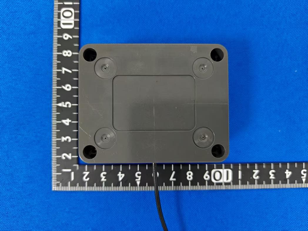
UOXSKYHAWKDUOSEN1
Dec 04, 2025Skyhawk Duo Sensor
Equipment Class
DTS - Digital Transmission System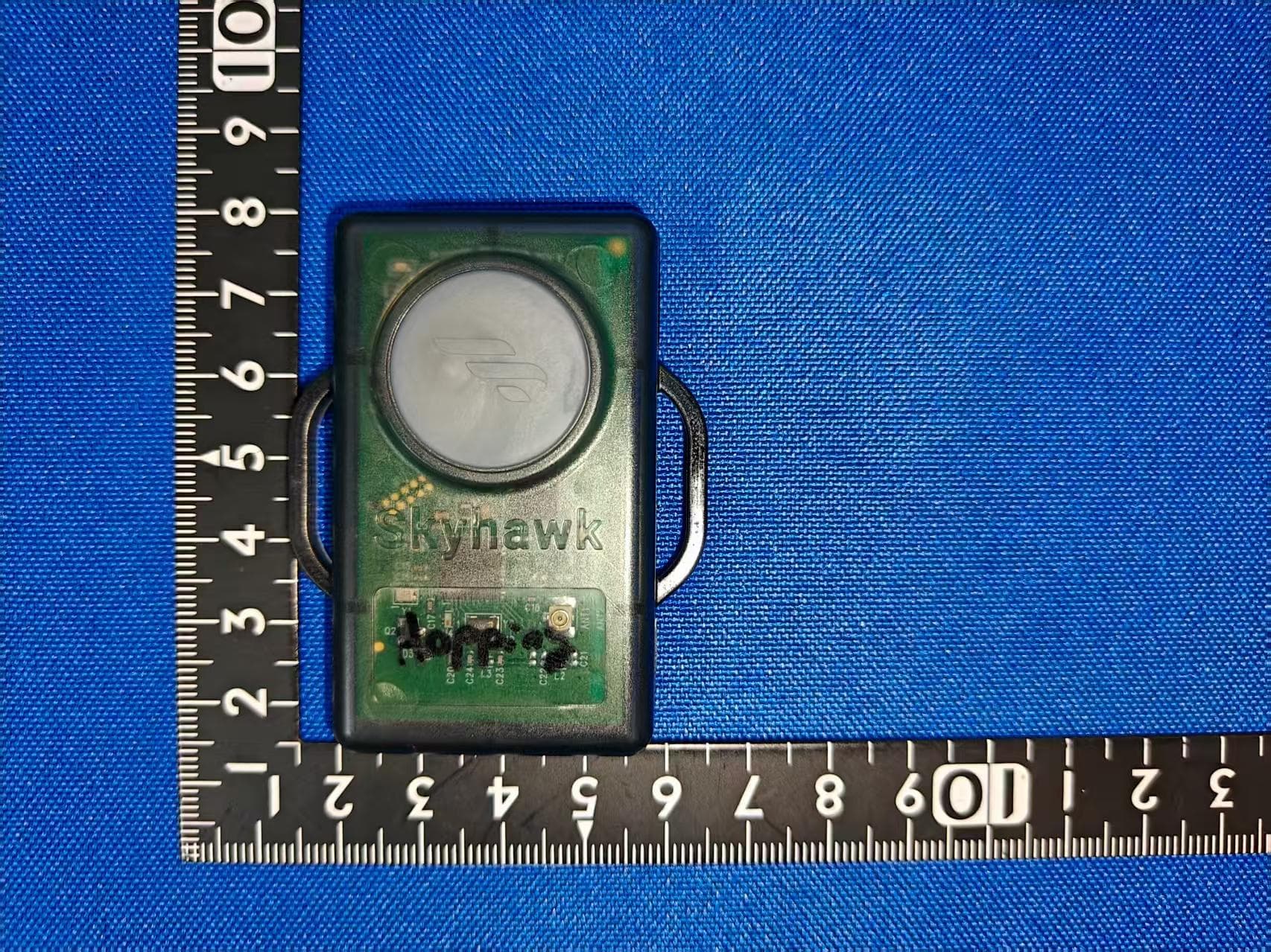
UOXSKYHAWKVERSEN1
Dec 04, 2025Skyhawk Versa Sensor
Equipment Class
DSS - Part 15 Spread Spectrum TransmitterUOXSKYHAWKTRESEN2
Jun 18, 2023Vibration/Magnet sensors for remote monitoring of rodents/wildlife traps
Equipment Class
DSS - Part 15 Spread Spectrum Transmitter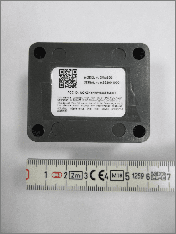
UOXSKYHAWKMSESEN1
Mar 22, 2020Mouse Sensor/Transceiver
Equipment Class
DXX - Part 15 Low Power Communication Device Transmitter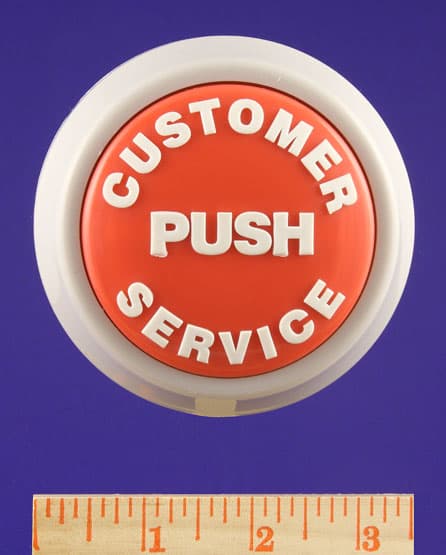
UOXALLIANCE38591
Mar 02, 2008EASY TOUCH BUTTON- 433 MHZ TRANSMITTER
Equipment Class
DSC - Part 15 Security/Remote Control Transmitter