UOXSKYHAWKMSESEN1Mouse Sensor/Transceiver
PICA Product Development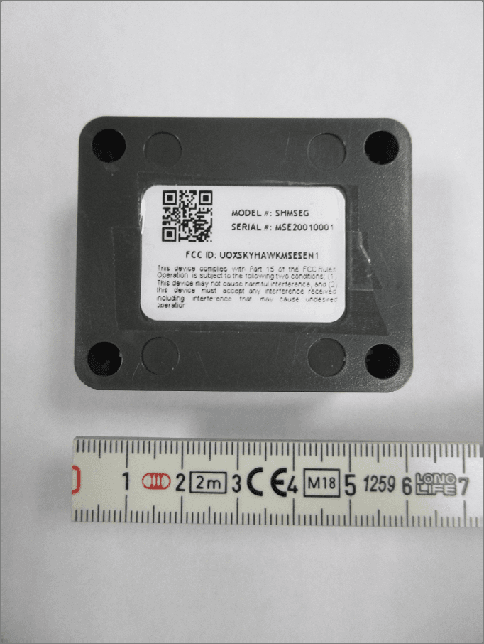
Click to zoom
Application Details
- Equipment Class
- DXX - Part 15 Low Power Communication Device Transmitter
- Date of Grant
- Mar 22, 2020
- Application Purpose
- Original Equipment
- Date of Application
- Mar 20, 2020
- Equipment Note
- Mouse Sensor/Transceiver
- Frequency Range
- 915.00000000 - 915.00000000
- Company
- PICA Product Development
- Country
- United States
Documents & Files
Document Text
Text extracted from the exhibit documents filed with the FCC. Open a document above to read the original.
Users Manual
Installation & User Manual 3 Index: Introduction ....................................................................................................................... Layout Summary............................................................................................................. Installation ....................................................................................................................... Battery Replacement ......................................................................................................... Start-Up Operation .......................................................................................................... Shut-Down Operation/Reset Operation.............................................................................. LED Indicators ................................................................................................................ Operation......................................................................................................................... Safety, FCC and Warranty................................................................................................. 3 4 - 5 6 - 9 10 - 12 13 14 15 16 17 - 18 Introduction: Unpacking and Inspection: Before you begin installation, unpack and verify you have all the correct parts. (1) Skyhawk Trapmate Mini (2) AA Lithium Batteries (2) Sets of 3M Dual-Lock Strips (4) Self-Stick Mounting Magnets (4) Self-Stick Rubber Mounting Feet (1) Lanyard (1) Warranty card If you are missing any of these parts STOP and request a replacement on sky-hawk.com/warranty. 4 Skyhawk Trapmate Mini Layout Summary: Front of Unit LED Indicator - This multicolored LED indicator will indicate when the Skyhawk Trapmate Mini is booting, has a low battery or is transmitting an alert. More details on the indicators colors can be found on page 14. Front Button - This multi-use button can be used for various functions. See pages 8 and 9 for more details. Cover Screws LED Indicator Front Button 5 Front of Unit (with cover removed) Battery Holder - The battery holder accommodates 2 x AA Batteries. It is suggested that 1.5 volt lithium batteries are used for extended life. LED Mounting Pins PC Card/Battery Holder 6 Skyhawk Trapmate Mini Installation: The Skyhawk Trapmate Mini can be installed using three main methods that include using the supplied 3M dual- lock strips, using the self-stick magnets to attach to a magnetic surface, or by using rubber feet. Method 1 : 3M Dual-Lock Strips Step 1: In the accessory kit locate the two sets of 3M dual-lock strips. Keep these strips together and do not separate them at this time! Step 2: Clean the rear surface of the Skyhawk Trapmate Mini for proper bonding of the strips. Step 3: Peel one side only of each set of strips to expose the adhesive and affix to the rear of the unit. Step 4: Make sure the area of where the Skyhawk Trapmate Mini will be attached has a clean surface for proper bonding of the strips. Do not separate the strips from the back of the unit at this time! Step 5: Peel the remaining side of each of the strips to expose the adhesive and position it on the object and press down on the whole Skyhawk Trapmate Mini unit. Do not remove the Skyhawk Trapmate Mini at this time - give the 3M dual-lock adhesive about 30-minutes to bond. Attach to Object 7 Skyhawk Trapmate Mini Installation: Method 2 : Self-Stick Mounting Magnets Step 1: In the accessory kit locate the four self-stick mounting magnets. Step 2: Clean the four recessed areas on the back of the Skyhawk Trapmate Mini for proper bonding of the magnets. Step 3: Peel back the paper on the rubber feet to expose the adhesive and affix them to the designated areas on the back of the unit. Step 4: The Skyhawk Trapmate Mini is ready to be mounted. Make sure the area of where the Skyhawk Trapmate Mini will be attached is magnetic, and has a clean surface for proper mounting of the magnets. Attach to Object 8 Skyhawk Trapmate Mini Installation (continued): Method 3 : Self-Stick Rubber Mounting Feet Step 1: In the accessory kit locate the four self-stick rubber mounting feet. Step 2: Clean the four recessed areas on the back of the Skyhawk Trapmate Mini for proper bonding of the rubber feet. Step 3: Peel back the paper on the rubber feet to expose the adhesive and affix them to the designated areas on the back of the unit. Step 4: The Skyhawk Trapmate Mini is ready to be mounted. 9 Prevent Falling HazardPrevent Unit Fall Damage Installation - Safety Guidelines: Make sure when placing the Skyhawk Trapmate Mini on an object that it is securely attached and cannot fall off and injure someone or fall onto a hard surface and damage the unit. Make sure that when placing the Skyhawk Trapmate Mini it will not interfere with other equipment. 10 The Skyhawk Trapmate Mini comes with two AA 1.5 volt lithium batteries already installed. Depending upon use it may take several years before the batteries need to be replaced. When they are replaced it is suggested to use a high quality name brand AA lithium battery like an Energizer Advanced Lithium or Ultimate Lithium battery. Follow the instructions below to replace these batteries Skyhawk Trapmate Mini Battery Replacement: Step 2: Remove the front cover. There may be gasket holding the unit together so it might take a small bit of force to separate the cover from the enclosure. Step 1: Remove the cover screws of the Skyhawk Trapmate Mini using a Phillips screwdriver. Make sure to turn the screws counter clock-wise. 11 Step 3: Remove the PC card/Battery holder from the enclosure. This can easily be done by turning the unit over and allowing the battery holder to fall into your hand Skyhawk Trapmate Mini Battery Replacement: Step 3: Remove and dispose of the old batteries properly. 12 Skyhawk Trapmate Mini Battery Replacement (continued): Step 6: Replace PC card/battery holder by aligning holes to the mounting pins in the enclosure. Replace cover making sur…
Text truncated - open the document above for the full version.
Cover Letter(s)
PICA Product Development LLC 4 Ash Street Extension | Derry | NH | 03038 603.425.1096 | 800.344.4685 picapd.com Letter Of Agency Date: February 5, 2020 RE: FCC ID: UOXSKYHAWKMSESEN1 To Whom It May Concern: Please be advised that Scott Stapleford of PICA Product Development authorizes Larry Stillings of Compliance Worldwide, Inc. to act on our behalf, until otherwise notified, for applications submitted for the purpose of obtaining an FCC Grant of Equipment Authorization. We certify that we are not subject to denial of federal benefits, that includes FCC benefits, pursuant to Section 5301 of the Anti-Drug Abuse ACT of 1988, U.S.C. 862. Further, no party, as defined in 47 CFR 1.2002(b), to the application is subject to denial of federal benefits, that includes FCC benefits. Thank you for your attention to this matter. Signatory Scott Stapleford
Cover Letter(s)
PICA Product Development LLC 4 Ash Street Extension | Derry | NH | 03038 603.425.1096 | 800.344.4685 picapd.com Date: February 5, 2020 Federal Communications Commission Authorization and Evaluation Division Confidentiality Request regarding application for certification of FCC ID: UOXSKYHAWKMSESEN1 Pursuant to Sections 0.457 and 0.459 of the Commission’s Rules, we hereby request confidential treatment of information accompanying this application as outlined below: Exhibit T ype File Name Block Diagram Block Diagram Schematics Operational Description UOXSKYHAWKMSESEN1 BlkDia1.pdf UOXSKYHAWKMSESEN1 BlkDia2.pdf UOXSKYHAWKMSESEN1 Schem.pdf UOXSKYHAWKMSESEN1 OpDes.pdf The above materials contain trade secrets and proprietary information not customarily released to the public. The public disclosure of these materials may be harmful to the applicant and provide unjustified benefits to its competitors. The applicant understands that pursuant to Section 0.457 of the Rules, disclosure of this application and all accompanying documentation will not be made before the date of the Grant for this application. Pursuant to DA04-1705 June 15, 2004 of the Commission’s public notice, we also require temporary confidential treatment of information accompanying this application as outlined below for a period of 180 days: Exhibit T ype File Name Internal Photos Internal Photos UOXSKYHAWKMSESEN1 IntPho1.pdf UOXSKYHAWKMSESEN1 IntPho2.pdf Temporary confidentiality for 180 days from public disclosure is important for PICA Product Development from a commercial perspective. It enables the company to complete its development and regulatory efforts prior to introducing the product to the marketplace. Releasing information on the product via the FCC website prior to formal market introduction can be confusing to our customers, and places the company at a competitive disadvantage. Sincerely, Scott Stapleford
External Photos
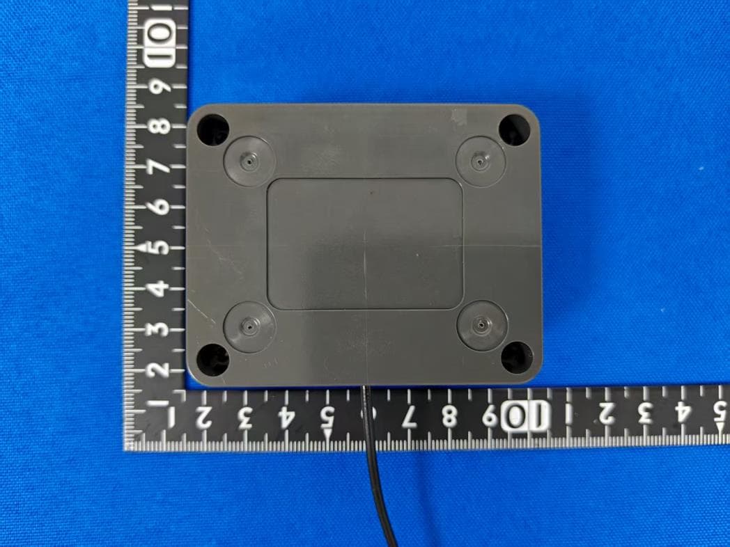
External Photos – UOXSKYHAWKMSESEN1 Front Back Bottom Left Right Top
ID Label/Location Info
` Work Instructions - Label Specification Document #: skyhawkmse_ls_1_rev_a W = White G = Gray YY = Year WW = Week XXXX = Squential # staring at 0001 each week 305-SHMSESEN 1.50” x 1.00” x .125”R Polyester Label Supply Part Number: Zebra 10023329 (305-SHLABEL3) Resin Ribbon Part Number: Zebra Zebra 03200GS11007 (305-RESINRIBBON1) MODEL #: SHMSEG SERIAL #: MSE20010001 QR Code SN SN - 11 characters ______________ QC Setup Model - Model 2 Density - .013 (Medium) Error Correction: Standard Rotation: Normal Data Source : Linked FCC ID: UOXSKYHAWKMSESEN1 Scale 2:1 If final test fails replace the FCC statement line with “FAIL” and any possible explanation of failure. This device complies with Part 15 of the FCC Rules. Operation is subject to the following two conditions: (1) this device may not cause harmful interference, and (2) this device must accept any interference received, including interference that may cause undesired operation.
Internal Photos
, , - . . . � .. empowered by
RF Exposure Info
Test Number: 142-20 Issue Date: 2/29/2020 Page 14 of 24 Compliance Worldwide, Inc. - 357 Main Street - Sandown, NH 03873 (603) 887 3903 Fax (603) 887 6445 www.complianceworldwide.com 6. Measurement Data (continued) 6.9. Public Exposure to Radio Frequency Energy Levels ((1.1307 (b)(1)) RSS-GEN, ISSUE 4 5.5, RSS 102) 6.9.1. (1.1307 (b)(1) Requirements Requirement: Portable devices are subject to radio frequency radiation exposure requirements. For a 1-g SAR, the test exclusion result must be ≤ 3.0. Test Notes: The 1-g and 10-g SAR test exclusion thresholds for 100 MHz to 6 GHz at test separation distances ≤ 50 mm are determined by the following formula: SAR Test Exclusion = (1) P MAX mW Maximum power of channel, including tune-up tolerance d MIN mm Minimum test separation distance, mm (≤ 50 mm) f (GHz) GHz f (GHz) is the RF channel transmit frequency in GHz (>100 MHz and <6 GHz) (1) FCC OET 447498 - Mobile and Portable Devices RF Exposure Procedures and Equipment Authorization Policies. Conclusion: Compliant - The device under test meets the exclusion requirement detailed in FCC OET 447498. Input: P MAX 1 (mW) 0.0675 d MIN (mm) 5.0000 f (GHz) 0.9150 Test Exclusion: 0.00008 Limit Exemption: 3.00000 1 Taken from column 5 of the table in Section 7.4 of this test report. 6.9.2. RSS-102 Issue 5 Requirements Requirement: SAR evaluation is required if the separation distance between the user and/or bystander and the antenna and/or radiating element of the device is less than or equal to 20 cm, except when the device operates at or below the applicable output power level (adjusted for tune-up tolerance) for the specified separation distance defined in Table 1. Portable devices are subject to radio frequency radiation exposure requirements. Test Notes: The limit was taken from Table 1 of RSS-102 Issue 5. Frequency Separation Distance Maximum Power RSS-102 Limit Result (MHz) (mm) (mW) (mW) 915.00 ≤5 0.0675 16.24 Compliant P MAX d MIN x √f (GHz)
Test Report
Compliance Worldwide, Inc. - 357 Main Street - Sandown, NH 03873 (603) 887 3903 Fax (603) 887 6445 www.complianceworldwide.com COMPLIANCE WORLDWIDE INC. TEST REPORT 142-20 In Accordance with the Requirements of Federal Communications Commission CFR Title 47 Part 15.249, Subpart C Innovation, Science and Economic Development Canada RSS 210, Issue 10 Low Power License-Exempt Radio Communication Devices Intentional Radiators Issued to PICA Product Development, LLC 4 Ash Street Extension Derry, NH 03038 for the Skyhawk Trapmate mini FCC ID: UOXSKYHAWKMSESEN1 Report Issued on February 29, 2020 Tested by This test report shall not be reproduced, except in full, without written permission from Compliance Worldwide, Inc. Test Number: 142-20 Issue Date: 2/29/2020 Page 2 of 24 Compliance Worldwide, Inc. - 357 Main Street - Sandown, NH 03873 (603) 887 3903 Fax (603) 887 6445 www.complianceworldwide.com Table of Contents 1. Scope ............................................................................................................................... 3 2. Product Details ................................................................................................................. 3 2.1. Manufacturer ............................................................................................................ 3 2.2. Model Number .......................................................................................................... 3 2.3. Serial Number........................................................................................................... 3 2.4. Description of EUT ................................................................................................... 3 2.5. Power Source ........................................................................................................... 3 2.6. Hardware Revision ................................................................................................... 3 2.7. Software Revision ..................................................................................................... 3 2.8. Modulation Type ....................................................................................................... 3 2.9. Operating Frequency ................................................................................................ 3 2.10. EMC Modifications .................................................................................................. 3 3. Product Configuration ....................................................................................................... 3 3.1. EUT Hardware .......................................................................................................... 3 3.2. Support Equipment ................................................................................................... 3 3.3. Cables ...................................................................................................................... 3 3.4. Operational Characteristics & Software .................................................................... 4 3.5. Block Diagram .......................................................................................................... 4 4. Measurements Parameters .............................................................................................. 4 4.1. Measurement Equipment Used to Perform Test ....................................................... 4 4.2. Software Used to Perform Test ................................................................................. 5 4.3. Measurement & Equipment Setup ............................................................................ 5 4.4. Measurement Procedure .......................................................................................... 5 4.5. Choice of Operating Frequencies ............................................................................. 5 4.6. EUT Positions for Emissions Measurements ............................................................ 5 5. Measurement Summary ................................................................................................... 6 6. Measurement Data ........................................................................................................... 6 6.1. Antenna Requirement ............................................................................................... 6 6.2. Radiated Field Strength of Fundamental................................................................... 7 6.3. Radiated Field Strength of Harmonics ...................................................................... 8 6.4. Band Edge Measurements ....................................................................................... 9 6.5. Spurious Radiated Emissions ................................................................................. 10 6.6. Occupied Bandwidth ............................................................................................... 11 6.7. 99% Emission Bandwidth ....................................................................................... 12 6.8. Conducted Emissions ............................................................................................. 13 6.9. Public Exposure to Radio Frequency Energy Levels............................................... 14 7. Test Setup Photographs ..................................................................................................15 8. Test Site Description .......................................................................................................20 Appendix A ..........................................................................................................................21 Test Number: 142-20 Issue Date: 2/29/2020 Page 3 of 24 Compliance Worldwide, Inc. - 357 Main Street - Sandown, NH 03873 (603) 887 3903 Fax (603) 887 6445 www.complianceworldwide.com 1. Scope This test report certifies that the PICA Product Development Skyhawk Trapm…
Text truncated - open the document above for the full version.
Test Setup Photos
Test Number: 142-20 Issue Date: 2/29/2020 Page 15 of 24 Compliance Worldwide, Inc. - 357 Main Street - Sandown, NH 03873 (603) 887 3903 Fax (603) 887 6445 www.complianceworldwide.com 7. Test Setup Photographs 7.1 Radiated Spurious Emissions 10 kHz to 30 MHz, Front View Test Number: 142-20 Issue Date: 2/29/2020 Page 16 of 24 Compliance Worldwide, Inc. - 357 Main Street - Sandown, NH 03873 (603) 887 3903 Fax (603) 887 6445 www.complianceworldwide.com 7. Test Setup Photographs 7.2 Radiated Spurious Emissions < 30 MHz, Rear View Test Number: 142-20 Issue Date: 2/29/2020 Page 17 of 24 Compliance Worldwide, Inc. - 357 Main Street - Sandown, NH 03873 (603) 887 3903 Fax (603) 887 6445 www.complianceworldwide.com 7. Test Setup Photographs 7.3 Radiated Field Strength and Spurious Emissions, 30 MHz to 1 GHz, Rear View Test Number: 142-20 Issue Date: 2/29/2020 Page 18 of 24 Compliance Worldwide, Inc. - 357 Main Street - Sandown, NH 03873 (603) 887 3903 Fax (603) 887 6445 www.complianceworldwide.com 7. Test Setup Photographs 7.4. Radiated Harmonics and Spurious Emissions >1 GHz, Front View Test Number: 142-20 Issue Date: 2/29/2020 Page 19 of 24 Compliance Worldwide, Inc. - 357 Main Street - Sandown, NH 03873 (603) 887 3903 Fax (603) 887 6445 www.complianceworldwide.com 7. Test Setup Photographs 7.5. Radiated Harmonics and Spurious Emissions >1 GHz, Rear View
Contact Information
Applicant
Scott Stapleford(CTO)
Test Firm
Compliance Worldwide, Inc.Deb Bourbeau
Technical Specifications
| # | Rule Parts | Frequency Range | Power Output |
|---|---|---|---|
| 1 | 15C | 915 MHz - 915 MHz | - |
Other Applications from PICA Product Development
UOXSKYHAWKDUOSEN1
Dec 04, 2025Skyhawk Duo Sensor
Equipment Class
DTS - Digital Transmission System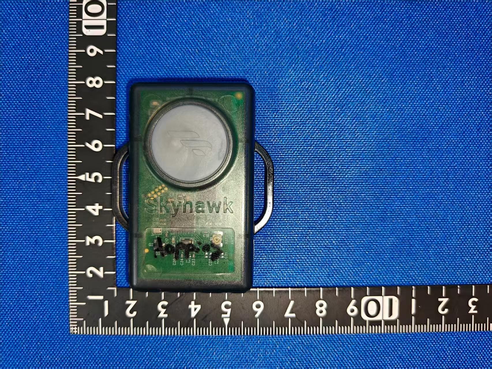
UOXSKYHAWKVERSEN1
Dec 04, 2025Skyhawk Versa Sensor
Equipment Class
DSS - Part 15 Spread Spectrum TransmitterUOXSKYHAWKTRESEN2
Jun 18, 2023Vibration/Magnet sensors for remote monitoring of rodents/wildlife traps
Equipment Class
DSS - Part 15 Spread Spectrum Transmitter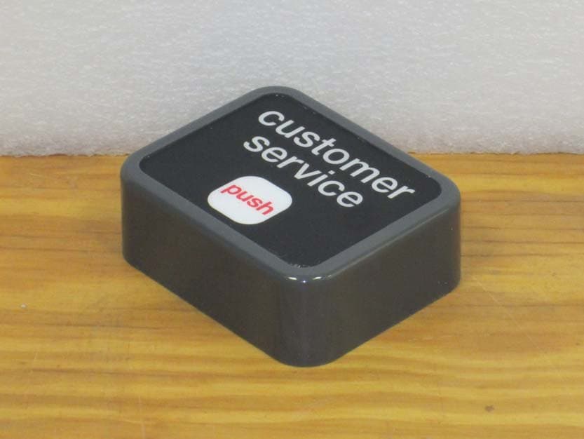
UOXNTLCSBUTTON
Nov 25, 2013434.0 MHz CUSTOMER SERVICE BUTTON
Equipment Class
DSC - Part 15 Security/Remote Control Transmitter
UOXALLIANCE38591
Mar 02, 2008EASY TOUCH BUTTON- 433 MHZ TRANSMITTER
Equipment Class
DSC - Part 15 Security/Remote Control Transmitter