UXZBSH200Bluetooth Analog Telephone adapter
Clipcomm, Inc.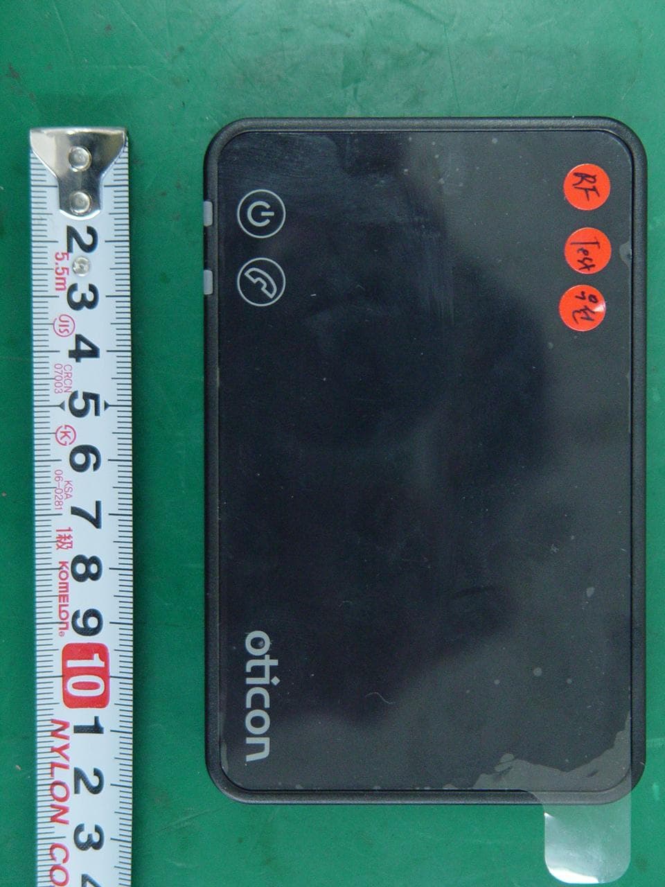
Click to zoom
Application Details
- Equipment Class
- DSS - Part 15 Spread Spectrum Transmitter
- Date of Grant
- Oct 14, 2012
- Application Purpose
- Original Equipment
- Date of Application
- Oct 14, 2012
- Equipment Note
- Bluetooth Analog Telephone adapter
- Frequency Range
- 2402.00000000 - 2480.00000000
- Company
- Clipcomm, Inc.
- Country
- South Korea
Documents & Files
Document Text
Text extracted from the exhibit documents filed with the FCC. Open a document above to read the original.
Users Manual
Order Number : GETEC-C1-12-289 FCC Part 15 subpart C Test Report Number : GETEC-E3-12-100 Page 1 / 1 EUT Type: Bluetooth Analog Telephone adapter FCC ID.: UXZBSH200 APPENDIX H : USER’S MANUAL InstructIons for use InstallatIon guIde 0000122272000001 thank you Thank you for choosing our product as your means to better hearing. To support your efforts, we have put great care and attention into making sure that your new Phone adapter has the highest quality and is easy to use and maintain. The Oticon landline phone solution (Phone adapter) enables you to make hands free phone conversation over most of the domestic area. The complete system description is documented on-line at www.oticon.com/phone. Here you will also find interactive presentations, “how to videos” and a support section with frequently asked questions. We recommend that you read this manual carefully to achieve the maximum benefit of your new Phone adapter, before you start to use it. If you have any questions to the use or maintenance of the Phone adapter, please contact your Hearing Care Professional. Indication for use The Phone adapter is intended to be used together with the Oticon Streamer and Oticon wireless hearing instruments. This enables the hearing instrument user to communicate wirelessly with a phone conversation partner via a landline phone. contents Package content 7 Phone adapter overview 8 Warnings 10 Installation 12 Connecting the Phone adapter to a power outlet 14 Connecting to phone line and landline phone 16 Pairing the Streamer to the Phone adapter 18 Technical in formation 22 I m p o rta n t no tIc e Please familiarise yourself with the entire contents of this booklet before using your Phone adapter. It contains instructions and important information about the use and handling of your Phone adapter. 7 package content Phone adaptor 2.0 – what is in the box The Phone adaptor box consists of the following elements: Phone adaptorPower supplyPhone cable placeHolderplaceHolder InstructIons for usestreamer ProInstructIons for usestreamer Pro This guide (Instructions for use) placeHolderplaceHolder når forsider er godkendt og der ikke sidder placeholder på placerer jeg korrekte pdf-f i ler 89 phone adapter overview Back Power supply Front Phone indicator ConditionPower indicator Phone indicator Power On, no connection to the Streamer Pairing with the Streamer The Streamer is wirelessly connected Incoming call Phone conversation Fault condition No light Blinking Steady OUT IN AUX POWER To landline phone To PSTN wall plug ConnectLine in/out* Power indicator * For more information please refer to: www.oticon.com/phone 1011 You should familiarize yourself fully with the following general warnings and the entire contents of this booklet before using your Phone adapter. Products to be connected to external equipment • The safety of the use of the Phone adapter with auxiliary input cable is determined by external signal source. When the input cable is connected to mains-operated equipment, this equipment must comply with IEC-60065, IEC-60601, IEC-60950 or equivalent safety standards. • The Phone adapter is designed to comply with the most stringent Standards of International Electromagnetic Compatibility. However, the Phone adapter might cause interference with other medical devices. Please contact relevant personnel to obtain permission before using the Phone adapter in hospitals or similar venues. • The Phone adapter is not a toy and therefore should be kept out of the reach of children and anyone else who might swallow parts or otherwise cause injury to themselves. Special attention should be paid to the smaller components in order to prevent children from swallowing them and choking. If a part is swallowed, see a doctor immediately. Warnings Warnings 12 Installation Activating the Phone adapter for the first time Before you can use the landline phone solution together with your hearing instruments, the Phone adapter must be connected to a power outlet and the public telephone line. This is a step-by-step guide on how to install the Phone adapter. All needed parts for the installation are included in the package. 1415 connecting the phone adapter to a power outlet Use the power supply with USB cable from box no. 1 1. Plug the USB connector into the “power” connector on Phone adapter 2. Plug the power supply into the mains wall socket or another power source 3. Check that power is turned on 4. After a f ew seconds the power indicator will light green 12 Box 1 4. 2. 1. 1617 connecting to phone line and landline phone Place the Phone adapter unit in a suitable spot near your landline phone or base station. 1. Unplug the phone line from the landline phone (or base station).* 2. Plug the phone line from the wall adapter into the Phone adapter “IN” connector. 3. Plug the tele cord from box 2 in the Phone adapter “OUT” connector. 4. Plug the other end of the t ele cord into the landline phone (or base station).* Please lift off the handset from of your landline phone – you should now be able to hear the dial tone from the handset speaker. 12 Box 2 3. 2. 1. 4. * if your main phone or base station does not have a detachable plug for the landline connection, you should either try using an alternative phone or a technician must be contacted to complete the installation. 1819 pairing the streamer to the phone adapter The very first time your Streamer is used with the Phone adapter, the Streamer must be paired to the Phone adapter. For pairing: 1. Make sure the Phone adap ter is powered on, i.e. the power indicator is steady green. 2. Press the Streamer connect button (Streamer) or on/off button (Streamer Pro) for 5-6 seconds until the blue light starts blinking. 3. Place the Streamer on top of the Phone adapter – the pairing takes around 20–60 seconds. 4. The pairing is completed when the power indicator on the Phone adapter and the on/off button on the Streamer turns steady blue. Pairing is done only once and will normally no…
Text truncated - open the document above for the full version.
Cover Letter(s)
SCS-F18: Project and Product Certification Representative Authorization Letter Page 1 of 2 Rev 2.0 2206 Ringwood Avenue San Jose, CA 95131 Tel: 408-526-1188 Fax: 408-526-1088 Email: [email protected] Project and Product Certification Representative Authorization Letter Reason for Amendment (current / obsolete) Revision History Approved Date From To Initial Release (current) 1.0 1.0 Nov-14-2006 Revised wording (current) 1.0 2.0 Sept–25-2007 SCS-F18: Project and Product Certification Representative Authorization Letter Page 2 of 2 Rev 2.0 Clipcomm Inc. E.S.T Bldg, 229-15, Nonhyeon-dong, Gangnam-gu, Seoul, 135-830, Korea Tel: +82-2-541-9081, Fax: +82-2-541-9085 October 10, 2012 To: SIEMIC, INC. 775 Montague Expressway Milpitas , CA 95035 USA Dear Sir/Madam, Re: Project and Product Certification Representative Authorization Letter We, SEIL Co., LTD, hereby authorize SIEMIC, INC. to act as a Certification Body for certifying for the following project(s): Product Name: Bluetooth Analog Telephone adapter FCC ID: UXZBSH200 We affirm that between SIEMIC and SEIL Co., LTD, any difference in understanding, including test plan, measurement methods, applicable standards and relevant procedures and processes have been resolved prior to commencement of testing activities. Sincerely, --------------------------------------------- Mr. Tae-Yoon Lim / Assistant Research Engineer Clipcomm Inc.
Cover Letter(s)
Confidentiality Request Letter Reason for Amendment (current / obsolete) Revision History Approved Date From To Initial Release (current) 1.0 1.0 Nov-14-2006 Clipcomm Inc. E.S.T Bldg, 229-15, Nonhyeon-dong, Gangnam-gu, Seoul, 135-830, Korea Tel: +82-2-541-9081, Fax: +82-2-541-9085 SCS-F19: Confidentiality Request Letter Rev 1.0 Nov 14, 2006 Federal Communications Commission Authorization and Evaluation Division October 10, 2012 Confidentiality Request regarding application for certification of FCC ID: UXZBSH200 We hereby request confidential treatment of information accompanying this application as outlined below: Exhibit Type File Name BLOCK DIAGRAM BSH200_BlkDia.pdf SCHEMETIC DIAGRAM BSH200_SchDia.pdf OPERATIONAL DESCRIPTION BSH200_OpeDes.pdf The above materials contain trade secrets and proprietary information not customarily released to the public. The public disclosure of these materials may be harmful to the applicant and provide unjustified benefits to its competitors. In addition to above mentioned documents, pursuant to Public DA 04-1705 of the Commission’s policy, in order to comply with the marketing regulations in 47 CFR 2.803 and the importation rules in 47 CFR 2.1204, while ensuring that business sensitive information remains confidential until the actual marketing of newly authorized devices. We are requesting the commission to grant short-term confidentiality request on the following for 180 days Exhibit Type File Name TEST SET UP PHOTOS BSH200_Tsup.pdf EXTERNAL PHOTOGRAPHS BSH200_ExtPho.pdf INTERNAL PHOTOGRAPHS BSH200_IntPho.pdf USER’S MANUAL BSH200_UseMan.pdf The applicant understands that pursuant to Section 0.457 & 0.459 of the Rules, disclosure of this application and all accompanying documentation will not be made before the date of the Grant for this application. Sincerely, --------------------------------------------- Mr. Tae-Yoon Lim / Assistant Research Engineer Clipcomm Inc.
External Photos
Order Number : GETEC-C1-12-289 FCC Part 15 subpart C Test Report Number : GETEC-E3-12-100 Page 1 / 10 EUT Type: Bluetooth Analog Telephone adapter FCC ID.: UXZBSH200 APPENDIX F : EXTERNAL PHOTOGRAPHS Order Number : GETEC-C1-12-289 FCC Part 15 subpart C Test Report Number : GETEC-E3-12-100 Page 2 / 10 EUT Type: Bluetooth Analog Telephone adapter FCC ID.: UXZBSH200 < Front > Order Number : GETEC-C1-12-289 FCC Part 15 subpart C Test Report Number : GETEC-E3-12-100 Page 3 / 10 EUT Type: Bluetooth Analog Telephone adapter FCC ID.: UXZBSH200 < Rear > Order Number : GETEC-C1-12-289 FCC Part 15 subpart C Test Report Number : GETEC-E3-12-100 Page 4 / 10 EUT Type: Bluetooth Analog Telephone adapter FCC ID.: UXZBSH200 < I/O port > Order Number : GETEC-C1-12-289 FCC Part 15 subpart C Test Report Number : GETEC-E3-12-100 Page 5 / 10 EUT Type: Bluetooth Analog Telephone adapter FCC ID.: UXZBSH200 < Adapter #1 > Order Number : GETEC-C1-12-289 FCC Part 15 subpart C Test Report Number : GETEC-E3-12-100 Page 6 / 10 EUT Type: Bluetooth Analog Telephone adapter FCC ID.: UXZBSH200 < Adapter #2 front > Order Number : GETEC-C1-12-289 FCC Part 15 subpart C Test Report Number : GETEC-E3-12-100 Page 7 / 10 EUT Type: Bluetooth Analog Telephone adapter FCC ID.: UXZBSH200 < Adapter #2 rear > Order Number : GETEC-C1-12-289 FCC Part 15 subpart C Test Report Number : GETEC-E3-12-100 Page 8 / 10 EUT Type: Bluetooth Analog Telephone adapter FCC ID.: UXZBSH200 < Phone cable > Order Number : GETEC-C1-12-289 FCC Part 15 subpart C Test Report Number : GETEC-E3-12-100 Page 9 / 10 EUT Type: Bluetooth Analog Telephone adapter FCC ID.: UXZBSH200 < Land line cable > Order Number : GETEC-C1-12-289 FCC Part 15 subpart C Test Report Number : GETEC-E3-12-100 Page 10 / 10 EUT Type: Bluetooth Analog Telephone adapter FCC ID.: UXZBSH200 < Aux cable >
ID Label/Location Info
Order Number : GETEC-C1-12-289 FCC Part 15 subpart C Test Report Number : GETEC-E3-12-100 Page 1 / 2 EUT Type: Bluetooth Analog Telephone adapter FCC ID.: UXZBSH200 APPENDIX B : ID SAMPLE LABEL & LOCATION Order Number : GETEC-C1-12-289 FCC Part 15 subpart C Test Report Number : GETEC-E3-12-100 Page 2 / 2 EUT Type: Bluetooth Analog Telephone adapter FCC ID.: UXZBSH200 LABELLING REQUIREMENTS The label shown shall be permanently affixed at a conspicuous location on the device and be readily visible to the user at the time of purchase. ID Label ID Label Location of EUT ID Label
Internal Photos
Order Number : GETEC-C1-12-289 FCC Part 15 subpart C Test Report Number : GETEC-E3-12-100 Page 1 / 4 EUT Type: Bluetooth Analog Telephone adapter FCC ID.: UXZBSH200 APPENDIX G : INTERNAL PHOTOGRAPHS Order Number : GETEC-C1-12-289 FCC Part 15 subpart C Test Report Number : GETEC-E3-12-100 Page 2 / 4 EUT Type: Bluetooth Analog Telephone adapter FCC ID.: UXZBSH200 < Inside > RF antenna Order Number : GETEC-C1-12-289 FCC Part 15 subpart C Test Report Number : GETEC-E3-12-100 Page 3 / 4 EUT Type: Bluetooth Analog Telephone adapter FCC ID.: UXZBSH200 < Main board front > Order Number : GETEC-C1-12-289 FCC Part 15 subpart C Test Report Number : GETEC-E3-12-100 Page 4 / 4 EUT Type: Bluetooth Analog Telephone adapter FCC ID.: UXZBSH200 < Main board rear >
RF Exposure Info
Order Number : GETEC-C1-12-289 FCC Certification Test Report Number : GETEC-E3-12-100 Page 1 / 3 EUT Type: Bluetooth Analog Telephone adapter FCC ID.: UXZBSH200 APPENDIX L : MAXIMUM PERMISSIBLE EXPOSURE Order Number : GETEC-C1-12-289 FCC Certification Test Report Number : GETEC-E3-12-100 Page 2 / 3 EUT Type: Bluetooth Analog Telephone adapter FCC ID.: UXZBSH200 Maximum Permissible Exposure 1.1 Applicable Standard Systems operating under the provisions of this section shall be operated in a manner that ensures that the public is not exposed to radio frequency energy levels in excess limit for maximum permissible exposure. In accordance with 47 CFR FCC Part 2 Subpart J, section 2.1091 this device has been defined as a mobile device whereby a distance of 0.2 m normally can be maintained between the user and the device (A) Limits for Occupational / Controlled Exposure Frequency range(MHz) Electric Field Strength (E) (V/m) Magnetic Field Strength (H) (A/m) Power Density(S) (mW/cm2) Averaging Time |E|2, |H|2 or S (minutes) 0.3 ~ 3.0 614 1.63 (100)* 6 3.0~30 1842/f 4.89/f (900/f)* 6 30~300 61.4 0.163 1.0 6 300 ~ 1,500 f/300 6 1,500 ~ 100,000 5.0 6 (B) Limits for General Population / Uncontrolled Exposure Frequency range(MHz) Electric Field Strength (E) (V/m) Magnetic Field Strength (H) (A/m) Power Density(S) (mW/cm2) Averaging Time |E|2, |H|2 or S (minutes) 0.3 ~ 1.34 614 1.63 (100)* 30 1.34 ~ 30 824/f 2.19/f (180/f)* 30 30~ 300 27.5 0.073 0.2 30 300 ~ 1,500 f/1500 30 1,500 ~ 100,000 1.0 30 Note: f=frequency in MHz; *Plane-wave equivalent power density 1.2 MPE Calculation Method d GP mVE 30 )/( Power Density: 377 )/( 2 2 E mWPd E = Electric field (V/m) P = Peak RF output power (W) G = EUT Antenna numeric gain (numeric) d = Separation distance between radiator and human body (m) The formula can be changed to 2 377 30 d GP Pd From the peak EUT RF output power, the minimum mobile separation distance, d=0.2m, as well as the gain of the used antenna, the RF power density can be obtained. Order Number : GETEC-C1-12-289 FCC Certification Test Report Number : GETEC-E3-12-100 Page 3 / 3 EUT Type: Bluetooth Analog Telephone adapter FCC ID.: UXZBSH200 1.3 Calculated Result and Limit Antenna type: chip antenna Antenna gain (dBi) Antenna gain (numeric) Peak output power (dBm) Peak output power (mW) Power Density (s) (mW/cm 2 ) Limit of Power density (S) (mW/cm 2 ) 1.50 1.41 7.09 5.12 0.001 439 1
Test Setup Photos
Order Number : GETEC-C1-12-289 FCC Part 15 subpart C Test Report Number : GETEC-E3-12-100 Page 1 / 4 EUT Type: Bluetooth Analog Telephone adapter FCC ID.: UXZBSH200 APPENDIX E : TEST SET UP PHOTOGRAPHS Order Number : GETEC-C1-12-289 FCC Part 15 subpart C Test Report Number : GETEC-E3-12-100 Page 2 / 4 EUT Type: Bluetooth Analog Telephone adapter FCC ID.: UXZBSH200 Conducted Test Picture (Front) Conducted Test Picture (Front) Order Number : GETEC-C1-12-289 FCC Part 15 subpart C Test Report Number : GETEC-E3-12-100 Page 3 / 4 EUT Type: Bluetooth Analog Telephone adapter FCC ID.: UXZBSH200 Radiated Test Picture (Front): Below 30 MHz Radiated Test Picture (Rear): Below 1 GHz Order Number : GETEC-C1-12-289 FCC Part 15 subpart C Test Report Number : GETEC-E3-12-100 Page 4 / 4 EUT Type: Bluetooth Analog Telephone adapter FCC ID.: UXZBSH200 Radiated Test Picture (Front): Above 1 GHz
Contact Information
Applicant
Tae-Yoon Lim(Engineer)
Test Firm
Gumi University EMC CenterTae-Sig Park
Technical Specifications
| # | Rule Parts | Frequency Range | Power Output |
|---|---|---|---|
| 1 | 15C | 2.40 GHz - 2.48 GHz | 5.10 mW |
Other Applications from Clipcomm, Inc.
UXZBSM100
Aug 12, 2010Bluetooth Mic
Equipment Class
DSS - Part 15 Spread Spectrum Transmitter
UXZHCC100
Jul 01, 2007Bluetooth Hands Free Car Kit
Equipment Class
DSS - Part 15 Spread Spectrum Transmitter
UXZHCM100
Feb 19, 2007Bluetooth Headset
Equipment Class
DSS - Part 15 Spread Spectrum Transmitter
UXZEDR-AP
Jan 25, 2007Bluetooth Access Point
Equipment Class
JBP - Part 15 Class B Computing Device Peripheral