UY6-FHLSMModule with communication function for sending and receiving data to and from compatible wireless devices
TOHNICHI MFG. CO., LTD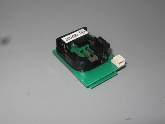
Click to zoom
Application Details
- Equipment Class
- DSS - Part 15 Spread Spectrum Transmitter
- Date of Grant
- Mar 01, 2021
- Application Purpose
- Original Equipment
- Date of Application
- Mar 01, 2021
- Equipment Note
- Module with communication function for sending and receiving data to and from compatible wireless devices
- Frequency Range
- 2402.00000000 - 2479.00000000
- Company
- TOHNICHI MFG. CO., LTD
- Country
- Japan
Documents & Files
Document Text
Text extracted from the exhibit documents filed with the FCC. Open a document above to read the original.
Users Manual
Integration guide TOHNICHI RF MODULE MODEL: FHLSM Board Board+FHLSM Applicable FCC Rules The following FCC rules are applicable to the radio module: CFR 47, Part 15.247 The radio module is only tested to the above FCC rules, therefore further testing is required for unintentional emissions to FCC Part 15, Subpart B after the radio module is integrated into the host. Limited module procedures This radio module is approved for integration into host model T-FHLSM-Sub Board. Integration into hosts that are different in construction require a Class II Permissive Change filing on the limited modular certification to allow use in other hosts. RF exposure considerations The antenna used for this transmitter must be installed to provide a separation distance of at least 20 cm from all persons and must not be co-located or operating in conjunction with any other antenna or transmitter. Antennas The module must only be used with the antennas provided. Label and Compliance information The following information must be provided to the user in the host user manual: CAUTION — Changes or modifications not expressly approved by the party responsible for compliance could void the user’s authority to operate the equipment. This device complies with Part 15 of the FCC Rules. Operation is subject to the following two conditions: (1) this device may not cause harmful interference, and (2) this device must accept any interference received, including interference that may cause undesired operation. The host which is equipped with FHLSM must be labeled with: Contains FCC ID: UY6-FHLSM Contains IC: 6561B-FHLSM
Users Manual
User Manual TOHNICHI RF MODULE MODEL: FHLSM The purpose of this manual is to explain correct way how to integrate module FHLSM to the end product. It includes procedures that shall assist you to avoid unforeseen problems. This manual presents information that shows how module and end product, where module integrated, complies with regulations in certain regions. Any modifications, not expressly approved by the manufacturer could void the authority to operate in these regions. The TOHNICHI RF MODULE, model FHLSM is installed in a portable device or in a fixed device. The usage is only for data transmission. And the FHLSM RF MODULE has to be installed and used in accordance with the technical description/installation instructions provided by the manufacturer. The system may only be implemented in the configuration that was authorized. Note that any changes or modifications to this equipment not expressly approved by the manufacturer could void the user’s authority to operate this equipment. Regulatory Information USA-Federal Communications Commission (FCC) This device complies with Part 15 of the FCC Rules. Operation is subject to the following two conditions: (1) This device may not cause harmful interference, and (2) This device must accept any interference received, including interference that may cause undesired operation. Any changes or modifications not expressly approved by the party responsible for compliance could void the user’s authority to operate the equipment. Labeling TOHNICHI RF MODULE FHLSM is labeled as below. FCC ID: UY6-FHLSM The proposed with FCC ID label format is to be placed on the module. If FCC ID is not visible when the module is installed into the system, “Contains FCC ID: UY6-FHLSM” shall be placed on the outside of final host system. Caution: Exposure to Radio Frequency Radiation. To comply with RF exposure compliance requirements, this device must not be co-located or operating in conjunction with any other antenna or transmitter. Operating by itself, the output power from this device is below the threshold where SAR measurements are required. Canada-Industry Canada (IC) This device complies with Industry Canada licence-exempt RSS standard(s). Operation is subject to the following two conditions: (1) This device may not cause interference, and (2) This device must accept any interference, including interference that may cause undesired operation of this device. Le présent appareil est conforme aux CNR d'Industrie Canada applicables aux appareils radio exempts de licence. L'exploitation est autorisée aux deux conditions suivantes : (1) il ne doit pas produire de brouillage et (2) l’ utilisateur du dispositif doit étre prêt à accepter tout brouillage radioélectrique reçu, même si ce brouillage est susceptible de compromettre le fomctionnement du dispositif. Labeling TOHNICHI RF MODULE FHLSM is labeled as below. IC: 6561B-FHLSM The proposed with IC ID label format is to be placed on the module. If IC ID is not visible when the module is installed into the system, “Contains IC: 6561B-FHLSM” shall be placed on the outside of final host system. Caution: Exposure to Radio Frequency Radiation. To comply with RF exposure compliance requirements, this device must not be co-located or operating in conjunction with any other antenna or transmitter. Operating by itself, the output power from this device is below the threshold where SAR measurements are required. Attention: Exposition aux radiations de fréquences radio. Pour se conformer aux exigences de conformité d'exposition aux RF, cet appareil ne doit pas être colocalisé ni fonctionner en conjonction avec une autre antenne ou transmetteur. D'exploitation par elle-même, la puissance de sortie de cet appareil est en dessous du seuil où les mesures SAR sont nécessaires. Instructions to OEM Integrators A User manual provided to the end user must indicate the operating requirements and conditions that must be observed to ensure compliance with the above-mentioned FCC /IC RF Exposure guideline.
Cover Letter(s)
Tohnichi Mfg. Co., Ltd. 2-12, Omori-Kita 2-Chome, Ota-Ku, Tokyo, Japan DCN:QAF1840 Issued:19/02/28 Revised:--/--/-- Date: January 26, 2021 Equipment Authorization Division Federal Communications Commission 7435 Oakland Mills Road Columbia, MD 21046 FCC ID: UY6-FHLSM Product Name: FHLSM Request for Confidentiality Pursuant to Sections 0.457 and 0.459 of the commission’s rules, we hereby request that the following documents be held confidential: Block diagram Schematics Parts list Operational Description These materials contain trade secrets and proprietary information and are not customarily released to the public. The public disclosure of this information might be harmful to the company and provide unjustified benefits to our competitors. Dated this 26 Day of January, 20 21 By: Satoshi Takaku Signature Printed Title: Deputy General Manager On behalf of : TOHNICHI MFG. CO., LTD. Telephone: +81-3-3762-7859
Cover Letter(s)
Tohnichi Mfg. Co., Ltd. 2-12, Omori-Kita 2-Chome, Ota-Ku, Tokyo, Japan DCN:QAF1839 Issued:19/02/28 Revised:--/--/-- Date: January 26, 2021 Equipment Authorization Division Federal Communications Commission 7435 Oakland Mills Road Columbia, MD 21046 Authority to Act as Agent FCC On our behalf, I appoint Cosmos Corporation, 718-1 Katsurase-Cho, Matsusaka-Shi, Mie-Ken 515-1104, Japan, to act as our agent in the preparation of this application for equipment certification. I certify that submitted documents properly describe the device or system for which equipment certification is sought. I also certify that each unit manufactured, imported or marketed, as defined in FCC regulations will have affixed to it a label identical to that submitted for approval with this application. In signing this letter, Applicant certifies that neither the applicant nor any party to the application is not subject to a denial of Federal benefits, that include FCC benefits, pursuant to Section 5301 of the Anti-Drug Abuse Act of 1988, 21 U.S.C. § 862 because of a conviction for possession or distribution of a controlled substance. See 47 CFR 1.2002(b) for the definition of a "party" for these purposes. For instances where our authorized agent signs the application for certification on our behalf, I acknowledge that all responsibility for complying with the terms and conditions for certification, as specified by Nemko North America Inc., still resides TOHNICHI MFG. CO., LTD., 2-12, Omori- kita 2-Chome, Ota-ku Tokyo 143-0016 Japan. Dated this 26 Day of January 20 21 Agency agreement expiration date: Usually Give 3 Months By: Satoshi Takaku Signature Printed Title: Deputy General Manager On behalf of : TOHNICHI MFG. CO., LTD. Telephone: +81-3-3762-7859
Cover Letter(s)
1 | P a g e Modular Approval Request - FCC RE: Request for modular approval Model: FHLSM FCC ID: UY6-FHLSM To whom it may concern, We formally request modular approval on the above reference device pursuant to the requirements of FCC publication 996369 D01 for modular approval of Part 15 devices. Modular approval requirement Yes No Comment* (a) The radio elements of the radio frequency circuitry must be shielded. Physical/discrete and tuning capacitors may be located external to the shield, but must be on the module assembly. ☒ ☐ (b) The module shall have buffered modulation/data input(s) (if such inputs are provided) to ensure that the module will comply with the requirements set out in the applicable FCC rule part under conditions of excessive data rates or over-modulation. ☒ ☐ (c) The module shall have its own power supply regulation on the module. This is to ensure that the module will comply with the requirements set out in the applicable standard regardless of the design of the power supplying circuitry in the host device which houses the module. ☒ ☐ (d) The module must certified with specific antennas and these antennas must be contain a permanently attached antenna, or contain a unique antenna connector, and be marketed and operated only with specific antenna(s). ☒ ☐ (e) The module shall be tested for compliance with the applicable standard in a stand-alone configuration, i.e. the module must not be inside another device during testing. ☒ ☐ (f) The module must be labelled with its permanently affixed FCC ID label, or use an electronic display. ☒ ☐ (g) The module shall comply with all specific rules applicable to the transmitter including all the conditions provided in the integration instructions provided by the grantee. ☒ ☐ (h) The module must comply with RF exposure requirements ☒ ☐ * Please provide a detailed explanation for each item 2 | P a g e Comment The FHLSM module is not for use with other manufacturers’ products. Based on the above information this request is for: ☒LIMITED ☐SINGLE modular approval. Sincerely, Satoshi Takaku 1/26/2021 Company name and address: TOHNICHI MFG. CO., LTD. 2-12, Omori-kita 2-Chome, Ota-ku Tokyo 143-0016 Japan 3 | P a g e Instructions: Please complete this form and copy to company letterhead. Signature: The request should be signed by the person who is listed as the contact person on the FCC Grantee database. Definitions: Single modular approval – If all of the answers in the checklist are “YES” then the product may be approved as a single modular approval. In this case the module may be placed in any host product and may be sold to third parties for integration into host products. Limited modular approval – If one or more of the single modular requirements in the checklist cannot be met, the product may be eligible for limited modular approval. In this case the approval is host specific and the product may only be integrated into host configurations for which it has been certified. A Class II Permissive Change may be filed to add host configurations.
Cover Letter(s)
Compliance list for INTEGRATION INSTRUCTIONS Sections 2.2 through 2.10 of 996369 D03 OEM. Requirement Yes No Comment Page No. 2.2 List of applicable FCC rules List the FCC rules that are applicable to the modular transmitter. These are the rules that specifically establish the bands of operation, the power, spurious emissions, and operating fundamental frequencies. DO NOT list compliance to unintentional-radiator rules (Part 15 Subpart B) since that is not a condition of a module grant that is extended to a host manufacturer. See also Section 2.10 below concerning the need to notify host manufacturers that further testing is required.3 X Page 1 of Integration guide 2.3 Summarize the specific operational use conditions Describe use conditions that are applicable to the modular transmitter, including for example any limits on antennas, etc. For example, if point-to- point antennas are used that require reduction in power or compensation for cable loss, then this information must be in the instructions. If the use condition limitations extend to professional users, then instructions must state that this information also extends to the host manufacturer’s instruction manual. In addition, certain information may also be needed, such as peak gain per frequency band and minimum gain, specifically for master devices in 5 GHz DFS bands. X Page 1 of User Manual 2.4 Limited module procedures If a modular transmitter is approved as a “limited module,” then the module manufacturer is responsible for approving the host environment that the limited module is used with. The manufacturer of a limited module must describe, both in the filing and in the installation instructions, the alternative means that the limited module manufacturer uses to verify that the host meets the necessary requirements to satisfy the module limiting conditions. A limited module manufacturer has the flexibility to define its alternative method to address the conditions that limit the initial approval, such as: shielding, minimum signaling amplitude, buffered modulation/data inputs, or power supply regulation. The alternative method could include that the limited module manufacturer reviews X Page 1 of Integration guide detailed test data or host designs prior to giving the host manufacturer approval. This limited module procedure is also applicable for RF exposure evaluation when it is necessary to demonstrate compliance in a specific host. The module manufacturer must state how control of the product into which the modular transmitter will be installed will be maintained such that full compliance of the product is always ensured. For additional hosts other than the specific host originally granted with a limited module, a Class II permissive change is required on the module grant to register the additional host as a specific host also approved with the module. 2.5 Trace antenna designs For a modular transmitter with trace antenna designs, see the guidance in Question 11 of KDB Publication 996369 D02 FAQ – Modules for Micro-Strip Antennas and traces. The integration information shall include for the TCB review the integration instructions for the following aspects: layout of trace design, parts list (BOM), antenna, connectors, and isolation requirements. 4 a) Information that includes permitted variances (e.g., trace boundary limits, thickness, length, width, shape(s), dielectric constant, and impedance as applicable for each type of antenna); b) Each design shall be considered a different type (e.g., antenna length in multiple(s) of frequency, the wavelength, and antenna shape (traces in phase) can affect antenna gain and must be considered); c) The parameters shall be provided in a manner permitting host manufacturers to design the printed circuit (PC) board layout; d) Appropriate parts by manufacturer and specifications; e) Test procedures for design verification; and f) Production test procedures for ensuring compliance. The module grantee shall provide a notice that any deviation(s) from the defined parameters of the antenna trace, as described by the instructions, require that the host product - - Not applicable manufacturer must notify the module grantee that they wish to change the antenna trace design. In this case, a Class II permissive change application is required to be filed by the grantee, or the host manufacturer can take responsibility through the change in FCC ID (new application) procedure followed by a Class II permissive change application. 2.6 RF exposure considerations It is essential for module grantees to clearly and explicitly state the RF exposure conditions that permit a host product manufacturer to use the module. Two types of instructions are required for RF exposure information: (1) to the host product manufacturer, to define the application conditions (mobile, portable – xx cm from a person’s body); and (2) additional text needed for the host product manufacturer to provide to end users in their end-product manuals. If RF exposure statements and use conditions are not provided, then the host product manufacturer is required to take responsibility of the module through a change in FCC ID (new application). X Page 2 of Integration guide 2.7 Antennas A list of antennas included in the application for certification must be provided in the instructions. For modular transmitters approved as limited modules, all applicable professional installer instructions must be included as part of the information to the host product manufacturer. The antenna list shall also identify the antenna types (monopole, PIFA, dipole, etc. (note that for example an “omni-directional antenna” is not considered to be a specific “antenna type”)). For situations where the host product manufacturer is responsible for an external connector, for example with an RF pin and antenna trace design, the integration instructions shall inform the installer that unique antenna connector must be used on the Part 15 authorized transmitters us…
Text truncated - open the document above for the full version.
External Photos
Page 1 of 1 Rev.00 ERF200420 Cosmos Corporation QAF1466 Issued: 13/03/01 Revised: 20/04/20 Test Report No. R160720 Appendix 2 External Photographs
ID Label/Location Info
Label Location Diagram Label
RF Exposure Info
Canada RSS-102 Issue 5 2.5.1 Exemption Limits for Routine Evaluation – SAR Evaluation IC: 6561B-FHLSM HVIN: FHLSM Frequency F: 2450 MHz Separation Distance d: ≤ 5 mm Antenna Gain G: 0 dBi E.I.R.P.: 0.83 mW Exemption Limit: 4 mW Margin of Compliance: 6.83 dB FCC 447498 D01 General RF Exposure Guidance v06 4.3.1. Standalone SAR test exclusion FCC ID: UY6-FHLSM Frequency: 2450 MHz Conducted Output Power P: 0.83 mW Separation Distance: ≤ 5 mm SAR Test Exclusion Threshold: (PmW/dmm) x √FGHz = (0.83/5) x √2.450 = 0.26 ≤ 3 for 1-g SAR
Test Report
Page 2 of 43 Project No. CJ20-160720E Test Report No. R160720 Rev.02 ERF201118 Cosmos Corporation QAF1466 Issued: 13/03/01 Revised: 20/04/20 718-1 Katsurase-cho, Matsusaka-shi, Mie 515-1104, Japan Tel:+81-598-60-1827 Fax:+81-598-60-0300 Contents Page 1. Description of the Tested Sample ............................................................................................. 3 1.1 Product Description ............................................................................................................. 3 1.2 Antenna Description ............................................................................................................ 3 1.3 EUT Description .................................................................................................................. 4 2. Summary of Test Results ......................................................................................................... 5 3. Test Condition .......................................................................................................................... 6 3.1 Mode of Operation .............................................................................................................. 6 3.2 Additional Equipment .......................................................................................................... 6 3.3 Configuration ....................................................................................................................... 7 3.4 EUT Angle........................................................................................................................... 8 4. General Information .................................................................................................................. 9 4.1 Test Methodology................................................................................................................ 9 4.2 Test Facility ......................................................................................................................... 9 4.3 Traceability.......................................................................................................................... 9 5. Test Result ............................................................................................................................. 10 5.1 Transmitter Spurious Emission (Radiated) (15.209, RSS-Gen 8.9) ................................... 10 5.2 20 dB Bandwidth (15.215(c), RSS-247 5.1)....................................................................... 21 5.3 Carrier Frequency Separation (15.247(a), RSS-247 5.1) ................................................... 23 5.4 Number of Hopping Channels (15.247(a), RSS-247 5.1) ................................................... 25 5.5 Time of Occupancy (15.247(a), RSS-247 5.1) ................................................................... 27 5.6 Maximum Peak Conducted Output Power and E.I.R.P. (15.247(b), RSS-247 5.4) ............ 29 5.7 Conducted Spurious Emission (15.247(d), RSS-247 5.5) .................................................. 31 5.8 Band Edge Measurement (15.247(d)) ............................................................................... 34 5.9 Occupied Bandwidth (RSS-Gen Annex A) ........................................................................ 39 6. Test Instrument List ................................................................................................................ 40 7. Appendix ................................................................................................................................ 42 Revision History ............................................................................................................................ 43 Page 3 of 43 Project No. CJ20-160720E Test Report No. R160720 Rev.02 ERF201118 Cosmos Corporation QAF1466 Issued: 13/03/01 Revised: 20/04/20 718-1 Katsurase-cho, Matsusaka-shi, Mie 515-1104, Japan Tel:+81-598-60-1827 Fax:+81-598-60-0300 1. Description of the Tested Sample 1.1 Product Description Product RF Module Model (referred to as the EUT) FHLSM Manufacturer TOHNICHI MFG. CO., LTD. Hardware Version Ver.02 Software Version Ver.44_06 Type of the Equipment Stand-alone Combined Equipment Plug-in Radio Device Other ( ) Transmitter Type WLAN ( ) Bluetooth ( ) ZigBee RFID ( ) Other Antenna Type Integral Antenna Dedicated External Antenna Number of Antenna 1 Antenna Operating Frequency Range 2402 MHz to 2479 MHz Number of Channel 78 ch Type of Modulation FHSS (GFSK) Other than FHSS Emission Designator W7D Type of Power Source AC Mains Dedicated AC Adaptor DC Voltage Battery Input Power Rating DC 3 V Type of Battery (if applicable) N/A Thermal Limitation 0 °C to 50 °C 1.2 Antenna Description Model Gain Antenna Type Un-specified * 0 dBi Pattern Antenna Note: *: The antenna does not have model name, because the antenna is a part of EUT. Page 4 of 43 Project No. CJ20-160720E Test Report No. R160720 Rev.02 ERF201118 Cosmos Corporation QAF1466 Issued: 13/03/01 Revised: 20/04/20 718-1 Katsurase-cho, Matsusaka-shi, Mie 515-1104, Japan Tel:+81-598-60-1827 Fax:+81-598-60-0300 1.3 EUT Description Equipment under test is as follow: Equipment Model Serial No. RF Module (EUT1) * 1 FHLSM E201023 RF Module (EUT2) * 2 FHLSM E201023-1 Note: * 1 : This equipment was used during the following tests; 20 dB Bandwidth, Carrier Frequency Separation, Number of Hopping Channels, Time of Occupancy, Maximum Peak Conducted Output Power, Band Edge Measurement, Conducted Spurious Emission and Occupied Bandwidth. * 2 : This equipment was used during the following tests; Transmitter Spurious Emissions (Radiated) and Band Edge Measurement. Page 5 of 43 Project No. CJ20-160720E Test Report No. R160720 Rev.02 ERF201118 Cosmos Corporation QAF1466 Issued: 13/03/01 Revised: 20/04/20 718-1 Katsurase-cho, Matsusaka-shi, Mie 515-1104, Japan Tel:+81-598-60-1827 Fax:+81-598-60-0300 2. Summary of Test Results These test results are the test results of…
Text truncated - open the document above for the full version.
Test Setup Photos
Page 1 of 3 Rev.00 ERF200420 Cosmos Corporation QAF1466 Issued: 13/03/01 Revised: 20/04/20 Test Report No. R160720 Appendix 1 Photographs of the Test Setup Radiated Spurious Emission (Below 1 GHz) Radiated Spurious Emission (Above 1 GHz) / Band Edge Measurement Page 2 of 3 Rev.00 ERF200420 Cosmos Corporation QAF1466 Issued: 13/03/01 Revised: 20/04/20 Test Report No. R160720 Appendix 1 (Continued) 20 dB Bandwidth / Maximum Peak Conducted Output Power and E.I.R.P. / Occupied Bandwidth / Carrier Frequency Separation / Number of Channels / Time of Occupancy / Conducted Spurious Emission Page 3 of 3 Rev.00 ERF200420 Cosmos Corporation QAF1466 Issued: 13/03/01 Revised: 20/04/20 Test Report No. R160720 Appendix 1 (Continued) Angle of EUT X axis Front View Y axis Front View Z axis Front View Right Side Left Side Right Side Left Side Right Side Left Side
Contact Information
Applicant
Satoshi Takaku
Test Firm
Cosmos CorporationYasuhiro Kawahara
[email protected]81 598 60 1827
Technical Specifications
| # | Rule Parts | Frequency Range | Power Output |
|---|---|---|---|
| 1 | 15C | 2.40 GHz - 2.48 GHz | 830.00 µW |
Other Applications from TOHNICHI MFG. CO., LTD
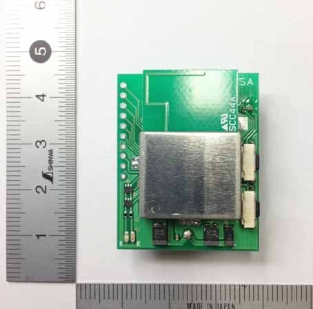
UY6-TFHSLS
Aug 11, 2013Remote Control Transmitter Module
Equipment Class
DXX - Part 15 Low Power Communication Device Transmitter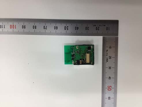
UY6-FMAM
May 05, 2013RF module
Equipment Class
DXT - Part 15 Low Power Transceiver, Rx Verified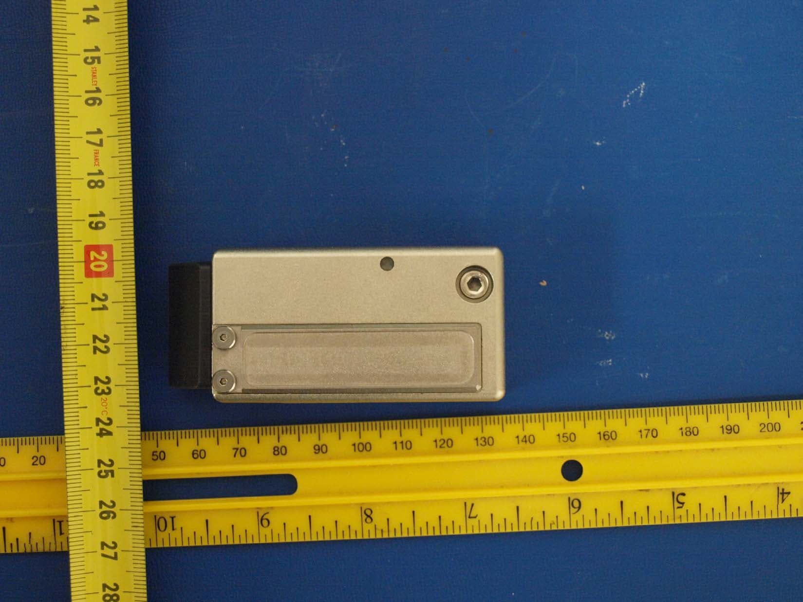
UY6-TFH256MCAR
Jan 31, 2011RF TRANSCEIVER
Equipment Class
DXT - Part 15 Low Power Transceiver, Rx VerifiedUY6-FHD256M
May 16, 2008RF Module
Equipment Class
DXT - Part 15 Low Power Transceiver, Rx Verified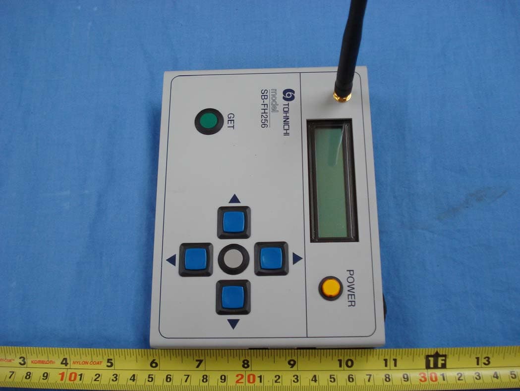
UY6-SBFH256
Sep 06, 2007RF SETTING BOX
Equipment Class
DXT - Part 15 Low Power Transceiver, Rx Verified