UY6-FMAMRF module
TOHNICHI MFG. CO., LTD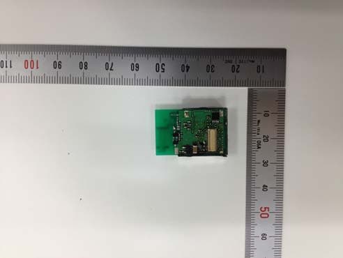
Click to zoom
Application Details
- Equipment Class
- DXT - Part 15 Low Power Transceiver, Rx Verified
- Date of Grant
- May 05, 2013
- Application Purpose
- Original Equipment
- Date of Application
- May 05, 2013
- Equipment Note
- RF module
- Frequency Range
- 902.50000000 - 927.50000000
- Company
- TOHNICHI MFG. CO., LTD
- Country
- Japan
Documents & Files
Document Text
Text extracted from the exhibit documents filed with the FCC. Open a document above to read the original.
Users Manual
User Manual TOHNICHI RF MODULE MODEL: FMAM The purpose of this manual is to explain correct way how to integrate module FMAM to the end product. It includes procedures that shall assist you to avoid unforeseen problems. This manual presents information that shows how module and end product, where module integrated, complies with regulations in certain regions. Any modifications, not expressly approved by the manufacturer could void the authority to operate in these regions. The TOHNICHI RF MODULE, model FMAM is installed in a portable device or in a fixed device. The usage is only for data transmission. And the FMAM RF MODULE has to be installed and used in accordance with the technical description/installation instructions provided by the manufacturer. The RF module is allowed to be used with internal chip antenna or with Dipole antenna used during test. The antenna gain of both antennas is 0dBi. When the antenna with higher antenna gain than 0dBi or a different type of antenna is used with this RF module, a submission of a permissive change application or a new application is required. For detail information concerning type approval of this module (e.g. where this module is already pre-approved) please contact the authorized local distributor or the manufacturer. The system may only be implemented in the configuration that was authorized. Note that any changes or modifications to this equipment not expressly approved by the manufacturer could void the user’s authority to operate this equipment. Regulatory Information USA-Federal Communications Commission (FCC) This equipment has been tested and found to comply with the limits for a Class B digital device, pursuant to Part 15 of FCC Rules. These limits are designed to provide reasonable protection against harmful interference in a residential installation. This equipment generates, uses, and can radiate radio frequency energy. If not installed and used in accordance with the instructions, it may cause harmful interference to radio communications. However, there is no guarantee that interference will not occur in a particular installation. If this equipment does cause harmful interference to radio or television reception, which can be determined by tuning the equipment off and on, the user is encouraged to try and correct the interference by one or more of the following measures: -Reorient or relocate the receiving antenna. -Increase the distance between the equipment and the receiver. -Connect the equipment to outlet on a circuit different from that to which the receiver is connected. -Consult the dealer or an experienced radio/TV technician for help. This device complies with Part 15 of the FCC Rules. Operation is subject to the following two conditions: (1) This device may not cause harmful interference, and (2) This device must accept any interference received, including interference that may cause undesired operation. Any changes or modifications not expressly approved by the party responsible for compliance could void the user’s authority to operate the equipment. Labeling TOHNICHI RF MODULE FMAM is labeled as below. FCC ID: UY6-FMAM The proposed with FCC ID label format is to be placed on the module. If FCC ID is not visible when the module is installed into the system, “Contains FCC ID: UY6-FMAM” shall be placed on the outside of final host system. Caution: Exposure to Radio Frequency Radiation. To comply with FCC RF exposure compliance requirements, this device must not be co-located or operating in conjunction with any other antenna or transmitter. Canada-Industry Canada (IC) This device complies with Industry Canada licence-exempt RSS standard(s). Operation is subject to the following two conditions: (1) This device may not cause interference, and (2) This device must accept any interference, including interference that may cause undesired operation of this device. Le présent appareil est conforme aux CNR d'Industrie Canada applicables aux appareils radio exempts de licence. L'exploitation est autorisée aux deux conditions suivantes : (1) il ne doit pas produire de brouillage et (2) l’ utilisateur du dispositif doit étre prêt à accepter tout brouillage radioélectrique reçu, même si ce brouillage est susceptible de compromettre le fomctionnement du dispositif. Labelling. TOHNICHI RF MODULE FMAM is labeled as below. IC: 6561B-FMAM The proposed with IC ID label format is to be placed on the module. If IC ID is not visible when the module is installed into the system, “Contains IC: 6561B-FMAM” shall be placed on the outside of final host system. Exposure to Radio Frequency Radiation. To comply with IC RF exposure compliance requirements, this device must not be co-located or operating in conjunction with any other antenna or transmitter. Instructions to OEM Integrators A User manual provided to the end user must indicate the operating requirements and conditions that must be observed to ensure compliance with the above-mentioned FCC /IC RF Exposure guideline. If this module is intended for use in a portable device, integrators are responsible for separate evaluation and/or approval to satisfy FCC/IC RF Exposure requirements. If an antenna with higher gain or new antenna type is used with this module, integrators must contact SMK for additional testing and submission to the FCC/IC. If other radio devices are to be integrated with this module, an additional evaluation and FCC/IC submission may be required. Integrators are responsible for such additional evaluation and FCC/IC submission.
External Photos
Model: FMAM FCC ID: UY6-FMAM IC: 6561B-FMAM External Photo <Top Side> <Bottom Side>
ID Label/Location Info
Model: FMAM FCC ID: UY6-FMAM IC: 6561B-FMAM Label and Label Location unit: mm Label located on the top of shield case.
Internal Photos
Model: FMAM FCC ID: UY6-FMAM IC: 6561B-FMAM Internal Photo <Top Side> <Bottom Side>
Test Report
RTL2610 FCC CFR47 PART 15 SUBPART C INDUSTRY CANADA RSS-210 ISSUE 8 CERTIFICATION TEST REPORT FOR RF MODULE MODEL NUMBER: FMAM FCC ID: UY6-FMAM IC: 6561B-FMAM REPORT NUMBER: 33IE0013-SH-A ISSUE DATE: April 26, 2013 Prepared for TOHNICHI MFG. CO., LTD 2-12, OMORI-KITA 2-CHOME, OTA-KU TOKYO 143-0016, JAPAN Prepared by UL Japan, Inc. Shonan EMC Lab. 1-22-3 Megumigaoka, Hiratsuka-shi, Kanagawa-ken 259-1220 JAPAN Telephone number : +81 463 50 6400 Facsimile number : +81 463 50 6401 JAB Accreditation No. : RTL02610 13-EM-F0429 REPORT NO: 33IE0013-SH-A DATE: April 26, 2013 FCC ID: UY6-FMAM IC: 6561B-FMAM Page 2 of 45 UL Japan, Inc. Shonan EMC Lab. 1-22-3 Megumigaoka, Hiratsuka-shi, Kanagawa-ken, 259-1220 JAPAN TEL: +81 463 50 6400 FAX: +81 463 50 6401 This report shall not be reproduced except in full, without the written approval of UL Japan, Inc. Revision History Rev. Issue Date Revisions Revised By -- 04/26/13 Initial Issue K. Adachi REPORT NO: 33IE0013-SH-A DATE: April 26, 2013 FCC ID: UY6-FMAM IC: 6561B-FMAM Page 3 of 45 UL Japan, Inc. Shonan EMC Lab. 1-22-3 Megumigaoka, Hiratsuka-shi, Kanagawa-ken, 259-1220 JAPAN TEL: +81 463 50 6400 FAX: +81 463 50 6401 This report shall not be reproduced except in full, without the written approval of UL Japan, Inc. TABLE OF CONTENTS 1. ATTESTATION OF TEST RESULTS ............................................................................................. 4 2. TEST METHODOLOGY .................................................................................................................. 5 3. FACILITIES AND ACCREDITATION .......................................................................................... 5 4. CALIBRATION AND UNCERTAINTY .......................................................................................... 5 4.1. MEASURING INSTRUMENT CALIBRATION ............................................................................. 5 4.2. SAMPLE CALCULATION ............................................................................................................ 5 4.3. MEASUREMENT UNCERTAINTY ............................................................................................... 5 5. EQUIPMENT UNDER TEST............................................................................................................ 6 5.1. DESCRIPTION OF EUT .............................................................................................................. 6 5.2. MAXIMUM OUTPUT E-FIELD STRENGTH .............................................................................. 6 5.3. DESCRIPTION OF AVAILABLE ANTENNAS ............................................................................. 6 5.4. SOFTWARE AND FIRMWARE .................................................................................................... 6 5.5. WORST-CASE CONFIGURATION AND MODE ......................................................................... 6 6. DESCRIPTION OF TEST SETUP ................................................................................................... 7 7. TEST AND MEASUREMENT EQUIPMENT ................................................................................ 9 8. TEST RESULTS ............................................................................................................................... 10 8.1. 20 dB AND 99% BANDWIDTH .................................................................................................. 10 8.2. RADIATED EMISSIONS ............................................................................................................. 19 8.2.1. TRANSMITTER BELOW 1 GHz ...................................................................................... 20 8.2.2. TRANSMITTER ABOVE 1 GHz ...................................................................................... 26 8.3. AC POWER LINE CONDUCTED EMISSIONS ......................................................................... 32 9. SETUP PHOTOS .............................................................................................................................. 37 REPORT NO: 33IE0013-SH-A DATE: April 26, 2013 FCC ID: UY6-FMAM IC: 6561B-FMAM Page 4 of 45 UL Japan, Inc. Shonan EMC Lab. 1-22-3 Megumigaoka, Hiratsuka-shi, Kanagawa-ken, 259-1220 JAPAN TEL: +81 463 50 6400 FAX: +81 463 50 6401 This report shall not be reproduced except in full, without the written approval of UL Japan, Inc. 1. ATTESTATION OF TEST RESULTS COMPANY NAME: TOHNICHI MFG. CO., LTD 2-12, OMORI-KITA 2-CHOME, OTA-KU TOKYO, 143-0016 JAPAN EUT DESCRIPTION: RF MODULE MODEL: FMAM SERIAL NUMBER: 1 (for Chip antenna), 2 (for Dipole antenna) DATE TESTED: April 11 to 24, 2013 APPLICABLE STANDARDS STANDARD TEST RESULTS CFR 47 Part 15 Subpart C Pass INDUSTRY CANADA RSS-210 Issue 8 Annex 8 Pass INDUSTRY CANADA RSS-GEN Issue 3 Pass UL Japan, Inc. tested the above equipment in accordance with the requirements set forth in the above standards. All indications of Pass/Fail in this report are opinions expressed by UL Japan, Inc. based on interpretations and/or observations of test results. The test results show that the equipment tested is capable of demonstrating compliance with the requirements as documented in this report. Note: The results documented in this report apply only to the tested sample, under the conditions and modes of operation as described herein. This document may not be altered or revised in any way unless done so by UL Japan, Inc. and all revisions are duly noted in the revisions section. Any alteration of this document not carried out by UL Japan, Inc. will constitute fraud and shall nullify the document. No part of this report may be used to claim product certification, approval, or endorsement by any government agency. Approved & Released For UL Japan, Inc. By: Tested By: Toyokazu Imamura Leader of WiSE Japan, UL Verification Service Kenichi Adachi Engineer of WiSE Japan, UL Verification Service (Representative) REPORT NO: 33IE0013-SH-A DATE: April 2…
Text truncated - open the document above for the full version.
Test Setup Photos
REPORT NO: 33IE0013-SH-A DATE: April 26, 2013 FCC ID: UY6-FMAM IC: 6561B-FMAM Page 37 of 45 UL Japan, Inc. Shonan EMC Lab. 1-22-3 Megumigaoka, Hiratsuka-shi, Kanagawa-ken, 259-1220 JAPAN TEL: +81 463 50 6400 FAX: +81 463 50 6401 This report shall not be reproduced except in full, without the written approval of UL Japan, Inc. 9. SETUP PHOTOS RADIATED RF MEASUREMENT SETUP (Chip antenna) RADIATED FRONT PHOTO RADIATED BACK PHOTO REPORT NO: 33IE0013-SH-A DATE: April 26, 2013 FCC ID: UY6-FMAM IC: 6561B-FMAM Page 38 of 45 UL Japan, Inc. Shonan EMC Lab. 1-22-3 Megumigaoka, Hiratsuka-shi, Kanagawa-ken, 259-1220 JAPAN TEL: +81 463 50 6400 FAX: +81 463 50 6401 This report shall not be reproduced except in full, without the written approval of UL Japan, Inc. RADIATED RF MEASUREMENT SETUP (Dipole antenna) RADIATED FRONT PHOTO RADIATED BACK PHOTO REPORT NO: 33IE0013-SH-A DATE: April 26, 2013 FCC ID: UY6-FMAM IC: 6561B-FMAM Page 39 of 45 UL Japan, Inc. Shonan EMC Lab. 1-22-3 Megumigaoka, Hiratsuka-shi, Kanagawa-ken, 259-1220 JAPAN TEL: +81 463 50 6400 FAX: +81 463 50 6401 This report shall not be reproduced except in full, without the written approval of UL Japan, Inc. RADIATED RF MEASUREMENT SETUP FOR PORTABLE CONFIGURATION (Chip antenna) X-AXIS PHOTO Y-AXIS PHOTO REPORT NO: 33IE0013-SH-A DATE: April 26, 2013 FCC ID: UY6-FMAM IC: 6561B-FMAM Page 40 of 45 UL Japan, Inc. Shonan EMC Lab. 1-22-3 Megumigaoka, Hiratsuka-shi, Kanagawa-ken, 259-1220 JAPAN TEL: +81 463 50 6400 FAX: +81 463 50 6401 This report shall not be reproduced except in full, without the written approval of UL Japan, Inc. Z-AXIS PHOTO REPORT NO: 33IE0013-SH-A DATE: April 26, 2013 FCC ID: UY6-FMAM IC: 6561B-FMAM Page 41 of 45 UL Japan, Inc. Shonan EMC Lab. 1-22-3 Megumigaoka, Hiratsuka-shi, Kanagawa-ken, 259-1220 JAPAN TEL: +81 463 50 6400 FAX: +81 463 50 6401 This report shall not be reproduced except in full, without the written approval of UL Japan, Inc. RADIATED RF MEASUREMENT SETUP FOR PORTABLE CONFIGURATION (Dipole antenna) (MODULE) X-AXIS PHOTO (MODULE) Y-AXIS PHOTO REPORT NO: 33IE0013-SH-A DATE: April 26, 2013 FCC ID: UY6-FMAM IC: 6561B-FMAM Page 42 of 45 UL Japan, Inc. Shonan EMC Lab. 1-22-3 Megumigaoka, Hiratsuka-shi, Kanagawa-ken, 259-1220 JAPAN TEL: +81 463 50 6400 FAX: +81 463 50 6401 This report shall not be reproduced except in full, without the written approval of UL Japan, Inc. (MODULE) Z-AXIS PHOTO REPORT NO: 33IE0013-SH-A DATE: April 26, 2013 FCC ID: UY6-FMAM IC: 6561B-FMAM Page 43 of 45 UL Japan, Inc. Shonan EMC Lab. 1-22-3 Megumigaoka, Hiratsuka-shi, Kanagawa-ken, 259-1220 JAPAN TEL: +81 463 50 6400 FAX: +81 463 50 6401 This report shall not be reproduced except in full, without the written approval of UL Japan, Inc. (ANTENNA) X-AXIS PHOTO (ANTENNA) Y-AXIS PHOTO REPORT NO: 33IE0013-SH-A DATE: April 26, 2013 FCC ID: UY6-FMAM IC: 6561B-FMAM Page 44 of 45 UL Japan, Inc. Shonan EMC Lab. 1-22-3 Megumigaoka, Hiratsuka-shi, Kanagawa-ken, 259-1220 JAPAN TEL: +81 463 50 6400 FAX: +81 463 50 6401 This report shall not be reproduced except in full, without the written approval of UL Japan, Inc. AC POWER LINE CONDUCTED EMISSIONS SETUP (Chip antenna) CONDUCTED FRONT PHOTO CONDUCTED SIDE PHOTO REPORT NO: 33IE0013-SH-A DATE: April 26, 2013 FCC ID: UY6-FMAM IC: 6561B-FMAM Page 45 of 45 UL Japan, Inc. Shonan EMC Lab. 1-22-3 Megumigaoka, Hiratsuka-shi, Kanagawa-ken, 259-1220 JAPAN TEL: +81 463 50 6400 FAX: +81 463 50 6401 This report shall not be reproduced except in full, without the written approval of UL Japan, Inc. (Dipole antenna) END OF REPORT CONDUCTED SIDE PHOTO CONDUCTED SIDE PHOTO
Contact Information
Applicant
Satoshi Takaku
Test Firm
UL Japan, Inc. Shonan EMC EMC Lab.Tetsuya Hashimoto
Technical Specifications
| # | Rule Parts | Frequency Range | Power Output |
|---|---|---|---|
| 1 | 15C | 902.5 MHz - 927.5 MHz | - |
Other Applications from TOHNICHI MFG. CO., LTD
UY6-FHLSM
Mar 01, 2021Module with communication function for sending and receiving data to and from compatible wireless devices
Equipment Class
DSS - Part 15 Spread Spectrum Transmitter
UY6-TFHSLS
Aug 11, 2013Remote Control Transmitter Module
Equipment Class
DXX - Part 15 Low Power Communication Device Transmitter
UY6-TFH256MCAR
Jan 31, 2011RF TRANSCEIVER
Equipment Class
DXT - Part 15 Low Power Transceiver, Rx VerifiedUY6-FHD256M
May 16, 2008RF Module
Equipment Class
DXT - Part 15 Low Power Transceiver, Rx Verified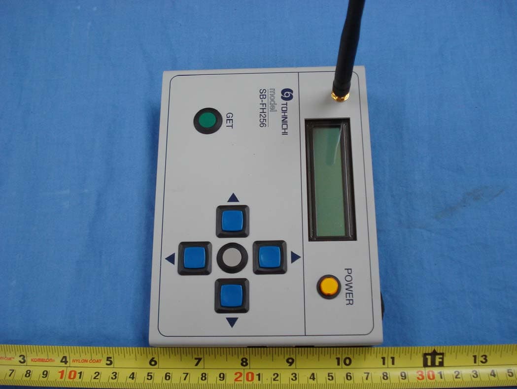
UY6-SBFH256
Sep 06, 2007RF SETTING BOX
Equipment Class
DXT - Part 15 Low Power Transceiver, Rx Verified