V8YFWA81US25005WMobile WiMAX USB Adapter
Accton Wireless Broadband Corp.
Click to zoom
Application Details
- Equipment Class
- TNB - Licensed Non-Broadcast Station Transmitter
- Date of Grant
- Mar 16, 2010
- Application Purpose
- Original Equipment
- Date of Application
- Mar 15, 2010
- Equipment Note
- Mobile WiMAX USB Adapter
- Frequency Range
- 2505.00000000 - 2685.00000000
- Country
- Taiwan
Documents & Files
Document Text
Text extracted from the exhibit documents filed with the FCC. Open a document above to read the original.
Users Manual
USER GUIDE Mobile WiMAX USB Adapter US211 USER GUIDE US211 IEEE 802.16e-2005 Mobile WiMAX USB Adapter, with 2.3, 2.5, and 3.5 GHz Frequency Band Models US211 E072009-AP-R01 149100000031W – 3 – COMPLIANCES FEDERAL COMMUNICATION COMMISSION INTERFERENCE STATEMENT This equipment has been tested and found to comply with the limits for a Class B digital device, pursuant to Part 15 of the FCC Rules. These limits are designed to provide reasonable protection against harmful interference in a residential installation. This equipment generates, uses and can radiate radio frequency energy and, if not installed and used in accordance with the instructions, may cause harmful interference to radio communications. However, there is no guarantee that interference will not occur in a particular installation. If this equipment does cause harmful interference to radio or television reception, which can be determined by turning the equipment off and on, the user is encouraged to try to correct the interference by one of the following measures: ◆Reorient or relocate the receiving antenna ◆Increase the separation between the equipment and receiver ◆Connect the equipment into an outlet on a circuit different from that to which the receiver is connected ◆Consult the dealer or an experienced radio/TV technician for help This device complies with Part 15 of the FCC Rules. Operation is subject to the following two conditions: (1) This device may not cause harmful interference, and (2) this device must accept any interference received, including interference that may cause undesired operation. FCC Caution: Any changes or modifications not expressly approved by the party responsible for compliance could void the user's authority to operate this equipment. IMPORTANT NOTE: FCC R ADIATION EXPOSURE STATEMENT This equipment complies with FCC radiation exposure limits set forth for an uncontrolled environment. End users must follow the specific operating instructions for satisfying RF exposure compliance. To maintain compliance with FCC RF exposure compliance requirements, please follow operation instruction as documented in this manual. This transmitter must not be co-located or operating in conjunction with any other antenna or transmitter. The availability of some specific channels and/or operational frequency bands are country dependent and are firmware programmed at the factory to match the intended destination. The firmware setting is not accessible by the end user. COMPLIANCES – 4 – Due to the essential high output power nature of WiMAX devices, use of this device with other transmitters at the same time may exceed the FCC RF exposure limit and such usage must be prohibited (unless such co- transmission has been approved by FCC in the future). SAR (SPECIFIC ABSORPTION RATE) COMPLIANCES STATEMENT SAR compliance has been established in typical laptop computer (s) with a USB slot, and the product can be used in typical laptop computers with USB slots. Other applications, such as handheld PCs or similar devices have not been verified and may not be in compliance with related RF exposure rules and such use shall be prohibited. EC CONFORMANCE DECLARATION Marking by the above symbol indicates compliance with the Essential Requirements of the R&TTE Directive of the European Union (1999/5/EC). This device is intended for use in the following European Community countries. NCC 警語 『減少電磁波影響請妥適使用』 – 5 – ABOUT THIS GUIDE PURPOSEThis guide details the hardware features of the US211 WiMAX USB Adapter, including its physical and performance-related characteristics, and how to install the device and use its configuration software. AUDIENCEThis guide is for PC users with a working knowledge of computers. You should be familiar with Windows operating system concepts. CONVENTIONSThe following conventions are used throughout this guide to show information: NOTE: Emphasizes important information or calls your attention to related features or instructions. CAUTION: Alerts you to a potential hazard that could cause loss of data, or damage the system or equipment. WARNING: Alerts you to a potential hazard that could cause personal injury. RELATED PUBLICATIONSThe following publication gives basic information on how to install and use the WiMAX USB Adapter. Quick Installation Guide Also, as part of the card’s configuration software, there is online help that describes all management features. REVISION HISTORYThis section summarizes the changes in each revision of this guide. JULY 2009 REVISION This is the first revision of this guide. This guide is valid for software version 2.0.0.0. – 6 – CONTENTS COMPLIANCES 3 A BOUT THIS GUIDE 5 C ONTENTS 6 1I NTRODUCTION 8 Features 8 System Requirements 9 Package Checklist 9 USB Connector 9 LED Indicators 10 2INSTALLATION 11 3C ONFIGURATION 15 Accessing the WCM Utility 15 Display Options 16 View Menu Options 17 Connection Management 17 Lost WiMAX Connection 18 Selecting Profiles 19 Editing a Profile 20 Card Settings 22 Network Information 25 WiMAX Connection Statistics 26 Tool Menu 27 Disable Menu Bar 27 Turning Power On/Off 27 Safely Remove Hardware 27 Lock WiMAX Network Adapter Now 28 Sounds for Events 28 Software Upgrade 29 CONTENTS – 7 – 4ADMINISTRATOR MODE 30 Accessing Administrator Mode 30 Setting Profiles 31 Creating a New Profile 32 Advanced Configuration 37 ATROUBLESHOOTING 39 Diagnosing LED Indicators 39 Network Connection Problems 39 Uninstalling the WCM Software 40 BSPECIFICATIONS 42 G LOSSARY 45 I NDEX 49 – 8 – 1INTRODUCTION The WiMAX USB Adapter is a network adapter that enables a notebook PC to connect to a service provider’s 2.3 GHz, 2.5 GHz or 3.5 GHz mobile WiMAX network. The USB adapter plugs directly into a PC’s compatible USB port and includes its own driver and configuration software for Windows XP and Windows Vista. Figure 1: WiMAX USB Adapter FEATURES ◆Mobile WiMAX IEEE 802.16e-2005 Wave 2 compliant ◆Three models for 2.3 GHz, 2.5 GHz or 3.5 GHz mobile WiMAX networks ◆Full Non-Line-o…
Text truncated - open the document above for the full version.
Users Manual
– 30 – 4ADMINISTRATOR MODE The WiMAX USB Adapter has an Administrator Mode for configuring profiles and accessing the Advanced Configuration settings. Administrator Mode is intended for qualified service personnel only. ACCESSING ADMINISTRATOR MODE Administrator Mode is accessed through the key sequence “Alt + t,” which prompts for a password. The password for Administrator Mode is “wimax123” (case sensitive). Figure 30: WCM Change Mode Once in Administrator Mode, the user can create, edit, and delete profiles, configure authentication settings, and access the Advance Configuration screen. Using the key sequence “Alt + t” a second time exits Administrator Mode. CHAPTER 4 | Administrator Mode Setting Profiles – 31 – Figure 31: Administrator Mode SETTING PROFILES The WCM profiles allow a user to set their specific details for connecting to various WiMAX networks. The WCM utility must have at least one profile configured and set as the Default Profile” to be able to connect to a WiMAX service. The WCM allows up to ten profiles to be configured. You can create, edit, and delete profiles in the list. One profile must be set as the “Default Profile.” CHAPTER 4 | Administrator Mode Setting Profiles – 32 – Figure 32: Setting Profiles CREATING A NEW PROFILE Clicking the Create button on the Profile screen displays the Create Profile window. Figure 33: Create Profile Screen - General Tab CHAPTER 4 | Administrator Mode Setting Profiles – 33 – The General tab on this screen displays the following items: Profile Name — A name used to identify the new profile (up to 20 characters). Select Service Provider — The ID number and name of the WiMAX network operator for this profile. You can click the Add button to add other operator names and IDs. Figure 34: Add Operator Operator Restriction — When set to “Home Operator,” the user can only connect to the service provider specified in the profile. When set to “No Operator Restriction,” the operator specified in the profile is used when the network is detected, otherwise the user can roam to other networks. Connection Mode — When set to “Auto Connection” the utility will use the profile settings to automatically scan and connect to a WiMAX network. Power Save Mode — To save power, the card can operate in one of three modes: ◆High: The card will go to sleep and idle whenever it can. ◆Medium: The card will go to sleep and idle only after a predefined time. ◆Application Optimized: The card will go to sleep and idle only when the PC operating system allows it. Save as Default Profile — Saves the profiles settings and sets it as the default. Clicking the Scan tab on the Add Profile screen displays the profile frequency and bandwidth settings. CHAPTER 4 | Administrator Mode Setting Profiles – 34 – Figure 35: Create Profile Screen - Scan Tab The Scan tab on the Add Profile screen displays the following items: Frequency — Specifies a center frequency to scan. Bandwidth — Specifies the bandwidth of the channel; 5, 7, 8.75, or 10 MHz. Clicking the Authentication tab on the Add Profile screen displays the user authentication settings. CHAPTER 4 | Administrator Mode Setting Profiles – 35 – Figure 36: Create Profile Screen - TTLS Authentication The Authentication tab on the Add Profile screen displays the following items: Enable Authentication — Enables user authentication for connection to the network. EAP Method — Selects the Extensible Authentication Protocol (EAP) method to use for authentication. When EAP-TTLS or EAP-TLS is selected, the appropriate parameters need to be configured. ◆EAP-TTLS-MSCHAPV2 — Tunneled Transport Layer Security with Microsoft’s version 2 of CHAP (Challenge-Handshake Authentication Protocol). This security method provides for certificate-based, mutual authentication of the client and network through an encrypted channel. Unlike EAP-TLS, EAP-TTLS requires only server-side certificates. The MS-CHAP protocol requires a user name and password to be configured. The user name and password can be up to 50 characters. (The following characters are not permitted; /\|”?@#$%^&*():;<>,.) ◆EAP-TLS — Transport Layer Security. Provides for certificate-based and mutual authentication of the client and the network. It relies on client- side and server-side certificates to perform authentication and can be used to dynamically generate user-based and session-based encryption keys to secure subsequent communications between the user and the network. CHAPTER 4 | Administrator Mode Setting Profiles – 36 – Outer Identity — The Network Access Identifier (NAI) text string that is used to identify the home authentication realm for device authentication during roaming. The NAI string (defined in RFC 4282) is used to proxy an authentication request to another remote server. The authentication is then performed using the unique X.509 authentication certificate included with the device. The string can be defined by three methods: ◆MAC: Uses the device MAC address as part of the identity. ◆RANDOM: Uses a generated random number of 26 hexadecimal digits. ◆CUSTOMIZE: Allows the whole string to be defined as required. Trust CA Certificate — The security certificate issued by a recognized certification authority (CA) that is used for mutual authentication with the authentication server when EAP-TLS is used. The browse button can be used to locate the file on the host PC. Certificate in EEPROM — Indicates if the device certificate, key, and password is included in memory on the device. If the certificate files are not in EEPROM, they can be located or specified using the following fields. ◆Client Certificate — The name of the file on the host PC that contains the device security certificate. The browse button can be used to locate the file. ◆Client Private Key — The name of the file on the host PC that contains the encryption key for use with the security certificate. ◆Client Private Key Password — The required password for the private key. User name — A text string used by EAP…
Text truncated - open the document above for the full version.
Cover Letter(s)
FCC Home | Search | RSS | Updates | E-Filing | Initiatives | Consumers | Find People Office of Engineering and Technology FCC > FCC E-filing > Inquiry System Home Page > Reply to OET Response FCC Site Map OET Home Page Site Options Basic KDB Search Advanced KDB Search Submit an Inquiry Reply to an Inquiry Response Category List FAQ Search Draft Laboratory Division Publications Draft Laboratory Division Publications (Expired) Draft Publication Moderation Policy Related Sites Equipment Authorization Presentations Equipment Authorization System (EAS) Telecommunications Certification Bodies (TCB) Reply to an OET Inquiry Response Currently Display Inquiry Tracking Number: 815417 Contact Information: Customer First Name: Hank Customer Last Name: Chung Telephone Number: 8865935343 Extension: 1746 E-mail Address: [email protected] Address: Line 1:No.81-1,Lu Liao Keng, 9th Ling,Wu Lung Tsuen, Chiu Line 2: P.O. Box: City:N/A State: Zip Code: Country: Taiwan Inquiry Details: First Inquiry Category: Radio Frequency Exposure - MPE; SAR Second Inquiry Category: Evaluation of SAR Third Inquiry Category: 802.16e (e.g. WiMAX) Dear Sir/Madam, This product is 802.16e/Wimax device which is 2.5GHz Wimax with 5MHz and 10MHz bandwidth. We follow 802.16e/WiMAX Permit-But-Ask and SAR Guidance requirement and provide necessary infromation to you. The product is USB dongle without swivel antenna and connector, for this kind of product that need to submit a KDB inquiry to determine the SAR test requirements,please refer to the attachment for the EUT detail. The SAR test proposal, we refer to KDB 447498 requirement. The SAR test configurations are show in the attachment, can we follow this test proposal as the attached file (SAR proposal.pdf) we provided to perform SAR measurement? Please advise if more information is required. Regards, ---Reply from Customer on 09/24/2009--- Dear Sir/Madam, The submitted result isn't copy from pba application for a different device. The device is Beceem chipset, some parameter as same previously Beceem chipset. All of parameter had confirmed by Beceem again, and they provide system operating prarmeters to us. (see "Beceem.pdf"attachement as Beceem reply by email) The result is from AWB's device for peak to average ration, duty cycle and scaling factor, not copy other device. Please advise if more information is required. Regards, ---Reply from Customer on 10/14/2009--- Dear Sir/Madam, The KDB 815417 and 487076 are that same chip call BCSM 250.(Beccem chip). So the " Wimax device and system operating parameters" information will just be same. Others materials (dutcycle plot ,peak to average ration, power , scaling factor) come from AWB sample, not same as KDB 487076. We select some data to prove between the two KDB.(See attachment "paper.pdf") Please advise if more information is required. Regards, ---Reply from Customer on 11/02/2009--- Dear Sir/Madam, To six question below, we have done the following answers. 第 1 頁,共 4 頁OET Inquiry System Reply to OET Response, Inquiry Tracking Number 815417 2009/12/3https://fjallfoss.fcc.gov/oetcf/kdb/forms/ReplyToResponse.cfm About Question 1: The maximum DL:UL is 29:18 that with control and traffic symbols. You can see attachemet "Time vector plots.pdf" and "System operating parameters.pdf" about more detail RF parameters. About Question 2: Its uplink is capable of both10 MHz and 5 MHz bandwidths. Its uplink is capable of both 10 MHz and 5 MHz bandwidths. For the 10 MHz bandwidth,it has 35 sub-channels structured from 1024 subcarriers; 184 are used as spare/safeguard subcarriers, leaving 840 available for transmission. From this, 560 subcarriers for data transmission with 280 subcarriers intended for pilot use. For the 5 MHz bandwidth, it contains 17 sub channels using 512 subcarriers; 104 subcarriers as spare/safeguard subcarriers, 272 for data transmission, and 136 for pilot. The up-link sub-frame is triggered by an Allocation Start Time contained in the information of UL-MAP. This information specifies the starting times of the Uplink and Downlink frames. In any UL sub-frame, the duty factor ranging and bandwidth information is used to ensure optimal system operation. In normal device transmission the device will transmit control signaling at the first 3 uplink symbols and then use the rest of the uplink symbols for data traffic bursts in the uplink sub-frame. Since the first 3 symbols are also used for ranging detection purposes and are shared among other device users, its transmitting power is much smaller than the data burst symbol power. During the testing modes the first 3 symbols have no power output and the data traffic bursts are always running at the maximum output power level. In the real usage, the data burst power will be adjusted according to the signal strength of the communication. In this way, by using the test mode arrangement we are transmitting at a worst case RF level. You can see attachemets " Time vector plots.pdf" and "Time vector values.pdf" About Question 3: You can see attachemet " SAR duty-factor scaling.pdf". We will show the maximum power with duty factor scaling in the SAR final report. About Question 4: We will revised to be consistent with this DL/UL # of symbols ration in the final SAR report. About Question 5: About PAR and SAR error, we will use your acceptable test mode and select worst mode by investigate to do it in final SAR report. About Question 6: You can see attachments "SAR measurement configurations.pdf" , " Test setup.pdf" and "signal generator.pdf". Additional attachments "power measurement.pdf" Please advise if more information is required. Regards, Response(s): --OET response sent on Sep 21 2009 12:13PM-- The submitted result is a "copy and paste" report from pba application for a different device. PBA applications for WIMAX SAR test results compliance must be specific to the device. Please explain the reason for the word for word "copy and paste" report from different device. Was any test condu…
Text truncated - open the document above for the full version.
External Photos
Page 1 CONSTRUCTION PHOTOS OF EUT
ID Label/Location Info
FCC ID: :: :V8YFWA81US25005W LABEL LOCATION The label will be permanently affixed at a conspicuous location on the device. Label here
Internal Photos
Page 2 Page 3
RF Exposure Info
Report No.: SA980810H03 1 Report Format Version 3.0.0 SAR TEST REPORT REPORT NO.: SA980810H03 FCC ID : V8YFWA81US25005W MODEL NO.: US211 RECEIVED: Aug. 10, 2009 TESTED: Sep. 11, 2009 ~ Jan. 08, 2010 ISSUED:Mar. 10, 2010 APPLICANT: Accton Wireless Broadband Corp. ADDRESS: 3F, No. 1 Creation Rd. III, Science-based Industrial Park Hsinchu 30077, Taiwan, R.O.C. ISSUED BY: Bureau Veritas Consumer Products Services (H.K.) Ltd., Taoyuan Branch LAB ADDRESS: No. 47, 14th Ling, Chia Pau Tsuen, Lin Kou Hsiang, Taipei Hsien 244, Taiwan, R.O.C. TEST LOCATION: No. 19, Hwa Ya 2nd Rd, Wen Hwa Tsuen, Kwei Shan Hsiang, Taoyuan Hsien 333, Taiwan, R.O.C. This test report consists of 52 pages in total except Appendix. It may be duplicated completely for legal use with the approval of the applicant. It should not be reproduced except in full, without the written approval of our laboratory. The client should not use it to claim product endorsement by TAF or any government agencies. The test results in the report only apply to the tested sample. Report No.: SA980810H03 2 Report Format Version 3.0.0 TABLE OF CONTENTS 1. CERTIFICATION ..................................................................................................................... 3 2. GENERAL INFORMATION ..................................................................................................... 4 2.1 GENERAL DESCRIPTION OF EUT ........................................................................................ 4 2.2 GENERAL DESCRIPTION OF APPLIED STANDARDS ....................................................... 15 2.3 GENERAL INOFRMATION OF THE SAR SYSTEM .............................................................. 16 2.4 GENERAL DESCRIPTION OF THE SPATIAL PEAK SAR EVALUATION ............................. 19 3. DESCRIPTION OF SUPPORT UNITS .................................................................................. 23 4. DESCRIPTION OF TEST MODES AND CONFIGURATIONS ............................................... 24 4.1. DESCRIPTION OF ANTENNA LOCATION ........................................................................... 24 4.2. CHECK FOR LINEARITY RESPONSE / WORST CASE / SCAN RESOLUTION ................. 25 4.3. DESCRIPTION OF ASSESSMENT POSITION ..................................................................... 29 5. TEST RESULTS .................................................................................................................... 30 5.1 TEST PROCEDURES ........................................................................................................... 30 5.2 MEASURED SAR RESULTS ................................................................................................ 32 5.3 SAR LIMITS .......................................................................................................................... 34 5.4 RECIPES FOR TISSUE SIMULATING LIQUIDS .................................................................. 35 5.5 TEST EQUIPMENT FOR TISSUE PROPERTY .................................................................... 39 6. SYSTEM VALIDATION .......................................................................................................... 40 6.1 TEST EQUIPMENT ............................................................................................................... 40 6.2 TEST PROCEDURE ............................................................................................................. 41 6.3 VALIDATION RESULTS ........................................................................................................ 43 6.4 SYSTEM VALIDATION UNCERTAINTIES ............................................................................ 44 7. MEASUREMENT SAR PROCEDURE UNCERTAINTIES ..................................................... 45 7.1. PROBE CALIBRATION UNCERTAINTY ............................................................................... 45 7.2. ISOTROPY UNCERTAINTY ................................................................................................. 46 7.3. BOUNDARY EFFECT UNCERTAINTY ................................................................................. 46 7.4. PROBE LINEARITY UNCERTAINTY .................................................................................... 47 7.5. READOUT ELECTRONICS UNCERTAINTY ........................................................................ 47 7.6. RESPONSE TIME UNCERTAINTY ...................................................................................... 47 7.7. INTEGRATION TIME UNCERTAINTY .................................................................................. 48 7.8. PROBE POSITIONER MECHANICAL TOLERANCE ............................................................ 49 7.9. PROBE POSITIONING ......................................................................................................... 49 7.10. PHANTOM UNCERTAINTY .................................................................................................. 50 7.11. DASY4 UNCERTAINTY BUDGET ........................................................................................ 51 8. INFORMATION ON THE TESTING LABORATORIES .......................................................... 52 APPENDIX A: TEST CONFIGURATIONS AND TEST DATA APPENDIX B: BVADT SAR MEASUREMENT SYSTEM APPENDIX C: PHOTOGRAPHS OF SYSTEM VALIDATION APPENDIX D: SYSTEM CERTIFICATE & CALIBRATION APPENDIX E: UL BURST PEAK-TO-AVERAGE POWER RATIO PLOTS APPENDIX F :DUTY CYCLE OF TEST SIGNAL Report No.: SA980810H03 3 Report Format Version 3.0.0 1. CERTIFICATION PRODUCT: Mobile WiMAX USB Adapter MODEL: US211 BRAND: AWB APPLICANT: Accton Wireless Broadband Corp. TESTED: Sep. 11, 2009 ~ Jan. 08, 2010 TEST SAMPLE: R&D SAMPLE STANDARDS: FCC Part 2 (Section 2.1093) FCC OET Bulletin 65, Supplement C (01-01) RSS-102 The above equipment (model: US211) has been tested by Bureau Veritas Consumer Products Services (H.K.) Ltd., Taoyuan Branch, and found complia…
Text truncated - open the document above for the full version.
RF Exposure Info
A - 1 APPENDIX A: Liquid Level Photo Tissue MSL2600MHz D=150mm A - 2 Date/Time: 2009/9/11 01:51:00 Test Laboratory: Bureau Veritas ADT M01-5M-QPSK1_2-Ch26 DUT: Mobile WiMax USB Adapter ; Type: US211 Communication System: FCC Wimax ; Frequency: 2505 MHz ; Duty Cycle: 1:3.19 ; Modulation type: QPSK Medium: MSL2600 Medium parameters used: f = 2505 MHz; σ = 2.07 mho/m; ε r = 51.7; ρ = 1000 kg/m 3 Phantom section: Flat Section ; Separation distance : 5 mm (The back side of the EUT to the Phantom) DASY4 Configuration: - Probe: EX3DV3 - SN3504 ; ConvF(7.33, 7.33, 7.33) ; Calibrated: 2009/1/21 - Sensor-Surface: 3mm (Mechanical Surface Detection) - Electronics: DAE3 Sn510 ; Calibrated: 2009/1/21 - Phantom: SAM 12 ; Type: SAM V4.0 ; Serial: TP 1202 - Measurement SW: DASY4, V4.7 Build 80 ; Postprocessing SW: SEMCAD, V1.8 Build 186 Low Channel 26/Area Scan (5x8x1): Measurement grid: dx=15mm, dy=15mm Maximum value of SAR (measured) = 0.849 mW/g Low Channel 26/Zoom Scan (7x7x7) (7x7x7)/Cube 0: Measurement grid: dx=5mm, dy=5mm, dz=5mm Reference Value = 19.0 V/m; Power Drift = -0.146 dB Peak SAR (extrapolated) = 1.57 W/kg SAR(1 g) = 0.765 mW/g; SAR(10 g) = 0.365 mW/g Maximum value of SAR (measured) = 0.997 mW/g A - 3 Date/Time: 2009/9/11 02:14:10 Test Laboratory: Bureau Veritas ADT M01-5M-QPSK1_2-Ch406 DUT: Mobile WiMax USB Adapter ; Type: US211 Communication System: FCC Wimax ; Frequency: 2600 MHz ; Duty Cycle: 1:3.19 ; Modulation type: QPSK Medium: MSL2600 Medium parameters used: f = 2600 MHz; σ = 2.23 mho/m; ε r = 51.4; ρ = 1000 kg/m 3 Phantom section: Flat Section ; Separation distance : 5 mm (The back side of the EUT to the Phantom) DASY4 Configuration: - Probe: EX3DV3 - SN3504 ; ConvF(7.33, 7.33, 7.33) ; Calibrated: 2009/1/21 - Sensor-Surface: 3mm (Mechanical Surface Detection) - Electronics: DAE3 Sn510 ; Calibrated: 2009/1/21 - Phantom: SAM 12 ; Type: SAM V4.0 ; Serial: TP 1202 - Measurement SW: DASY4, V4.7 Build 80 ; Postprocessing SW: SEMCAD, V1.8 Build 186 Mid Channel 406/Area Scan (5x8x1): Measurement grid: dx=15mm, dy=15mm Maximum value of SAR (measured) = 1.06 mW/g Mid Channel 406/Zoom Scan (7x7x7) (7x7x7)/Cube 0: Measurement grid: dx=5mm, dy=5mm, dz=5mm Reference Value = 21.7 V/m; Power Drift = -0.159 dB Peak SAR (extrapolated) = 1.89 W/kg SAR(1 g) = 0.869 mW/g; SAR(10 g) = 0.402 mW/g Maximum value of SAR (measured) = 1.15 mW/g A - 4 A - 5 Date/Time: 2009/9/11 02:29:42 Test Laboratory: Bureau Veritas ADT M01-5M-QPSK1_2-Ch746 DUT: Mobile WiMax USB Adapter ; Type: US211 Communication System: FCC Wimax ; Frequency: 2685 MHz ; Duty Cycle: 1:3.19 ; Modulation type: QPSK Medium: MSL2600 Medium parameters used: f = 2685 MHz; σ = 2.25 mho/m; ε r = 51; ρ = 1000 kg/m 3 Phantom section: Flat Section ; Separation distance : 5 mm (The back side of the EUT to the Phantom) DASY4 Configuration: - Probe: EX3DV3 - SN3504 ; ConvF(7.33, 7.33, 7.33) ; Calibrated: 2009/1/21 - Sensor-Surface: 3mm (Mechanical Surface Detection) - Electronics: DAE3 Sn510 ; Calibrated: 2009/1/21 - Phantom: SAM 12 ; Type: SAM V4.0 ; Serial: TP 1202 - Measurement SW: DASY4, V4.7 Build 80 ; Postprocessing SW: SEMCAD, V1.8 Build 186 High Channel 746/Area Scan (5x8x1): Measurement grid: dx=15mm, dy=15mm Maximum value of SAR (measured) = 0.792 mW/g High Channel 746/Zoom Scan (7x7x7) (7x7x7)/Cube 0: Measurement grid: dx=5mm, dy=5mm, dz=5mm Reference Value = 19.2 V/m; Power Drift = -0.082 dB Peak SAR (extrapolated) = 1.28 W/kg SAR(1 g) = 0.602 mW/g; SAR(10 g) = 0.283 mW/g Maximum value of SAR (measured) = 0.783 mW/g A - 6 Date/Time: 2010/1/8 02:06:22 Test Laboratory: Bureau Veritas ADT M02-5M-16Q1_2-Ch26 DUT: Mobile WiMax USB Adapter ; Type: US211 Communication System: Wimax_2.6GHz 5M ; Frequency: 2505 MHz ; Duty Cycle: 1:3.19 ; Modulation type: 16QAM Medium: MSL2600 Medium parameters used: f = 2505 MHz; σ = 2.07 mho/m; εr = 53.6; ρ = 1000 kg/m 3 Phantom section: Flat Section ; Separation distance : 5 mm (The back side of the EUT to the Phantom) DASY4 Configuration: - Probe: EX3DV3 - SN3504 ; ConvF(7.33, 7.33, 7.33) ; Calibrated: 2009/1/21 - Sensor-Surface: 3mm (Mechanical Surface Detection) - Electronics: DAE3 Sn579 ; Calibrated: 2009/7/17 - Phantom: SAM 12 ; Type: SAM V4.0 ; Serial: TP 1202 - Measurement SW: DASY4, V4.7 Build 80 ; Postprocessing SW: SEMCAD, V1.8 Build 186 Low Channel 26/Area Scan (5x8x1): Measurement grid: dx=15mm, dy=15mm Maximum value of SAR (measured) = 0.747 mW/g Low Channel 26/Zoom Scan (7x7x7) (7x7x7)/Cube 0: Measurement grid: dx=5mm, dy=5mm, dz=5mm Reference Value = 18.6 V/m; Power Drift = -0.083 dB Peak SAR (extrapolated) = 1.37 W/kg SAR(1 g) = 0.691 mW/g; SAR(10 g) = 0.340 mW/g Maximum value of SAR (measured) = 0.884 mW/g A - 7 Date/Time: 2009/9/11 03:52:00 Test Laboratory: Bureau Veritas ADT M02-5M-16Q1_2-Ch406 DUT: Mobile WiMax USB Adapter ; Type: US211 Communication System: FCC Wimax ; Frequency: 2600 MHz ; Duty Cycle: 1:3.19 ; Modulation type: 16QAM Medium: MSL2600 Medium parameters used: f = 2600 MHz; σ = 2.23 mho/m; ε r = 51.4; ρ = 1000 kg/m 3 Phantom section: Flat Section ; Separation distance : 5 mm (The back side of the EUT to the Phantom) DASY4 Configuration: - Probe: EX3DV3 - SN3504 ; ConvF(7.33, 7.33, 7.33) ; Calibrated: 2009/1/21 - Sensor-Surface: 3mm (Mechanical Surface Detection) - Electronics: DAE3 Sn510 ; Calibrated: 2009/1/21 - Phantom: SAM 12 ; Type: SAM V4.0 ; Serial: TP 1202 - Measurement SW: DASY4, V4.7 Build 80 ; Postprocessing SW: SEMCAD, V1.8 Build 186 Mid Channel 406/Area Scan (5x8x1): Measurement grid: dx=15mm, dy=15mm Maximum value of SAR (measured) = 0.838 mW/g Mid Channel 406/Zoom Scan (7x7x7) (7x7x7)/Cube 0: Measurement grid: dx=5mm, dy=5mm, dz=5mm Reference Value = 19.8 V/m; Power Drift = -0.178 dB Peak SAR (extrapolated) = 1.49 W/kg SAR(1 g) = 0.718 mW/g; SAR(10 g) = 0.348 mW/g Maximum value of SAR (meas…
Text truncated - open the document above for the full version.
Contact Information
Applicant
Abby Wei(Engineer)
Technical Contact
Bureau Veritas CPS (H.K.) Ltd. Taoyuan BranchEric Lin
[email protected]886-3-593-5343
81-1 Luliaoken, 9th Lin, Wulung Tsuen Chiunglin · Hsinchu · Taiwan
Non-Technical Contact
Bureau Veritas CPS (H.K.) Ltd. Taoyuan BranchEric Lin
[email protected]886-3-593-5343
Test Firm
Bureau Veritas CPS (H.K.) Ltd. Taoyuan BranchRichard Chen
Technical Specifications
| # | Rule Parts | Frequency Range | Power Output | Emission | Tolerance |
|---|---|---|---|---|---|
| 2 | 27 | 2.50 GHz - 2.69 GHz | 188.00 mW | 10M4W7D | 2.5 ppm |
Other Applications from Accton Wireless Broadband Corp.
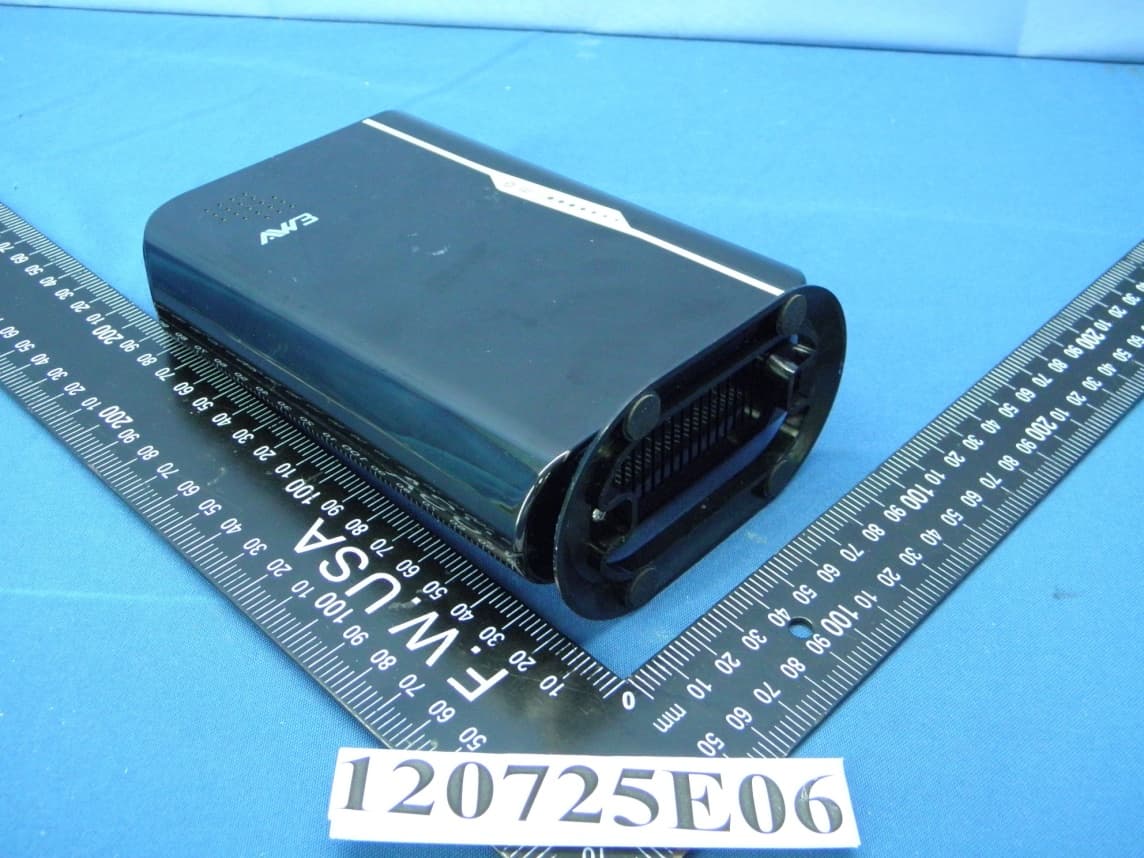
V8YFW181RG30015W
Nov 26, 2012WiMAX 802.16e Indoor Gateway
Equipment Class
DTS - Digital Transmission System
V8YFWA1FUS38000W
Sep 09, 2012WiMAX 802.16e USB Adapter
Equipment Class
TNB - Licensed Non-Broadcast Station Transmitter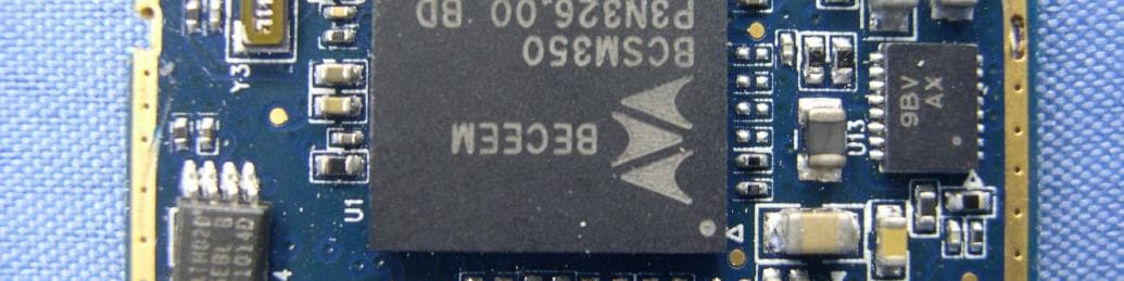
V8YFWE81MC30000W
Aug 02, 2011WiMAX 802.16e Mini Card
Equipment Class
TNB - Licensed Non-Broadcast Station Transmitter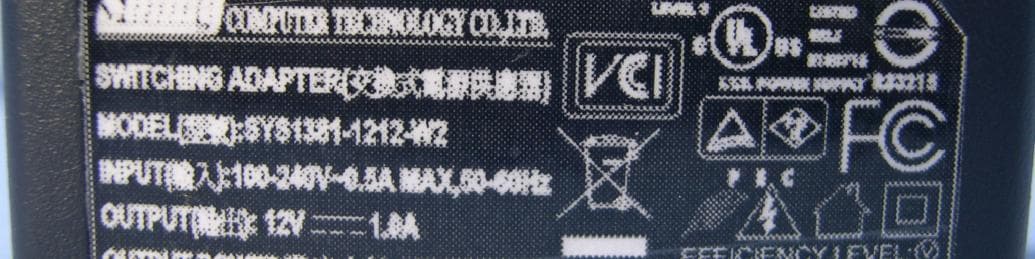
V8YFW181RG30000W
Apr 27, 2011WiMAX 802.16e Indoor Gateway
Equipment Class
DTS - Digital Transmission System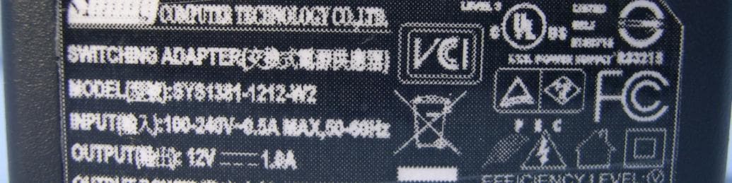
V8YFW181RG30002W
Apr 27, 2011WiMAX 802.16e Indoor Gateway
Equipment Class
TNB - Licensed Non-Broadcast Station Transmitter