V95-VTPWIRELESS THERMOSTAT DATA TERMINAL
Viconics Electronics Inc.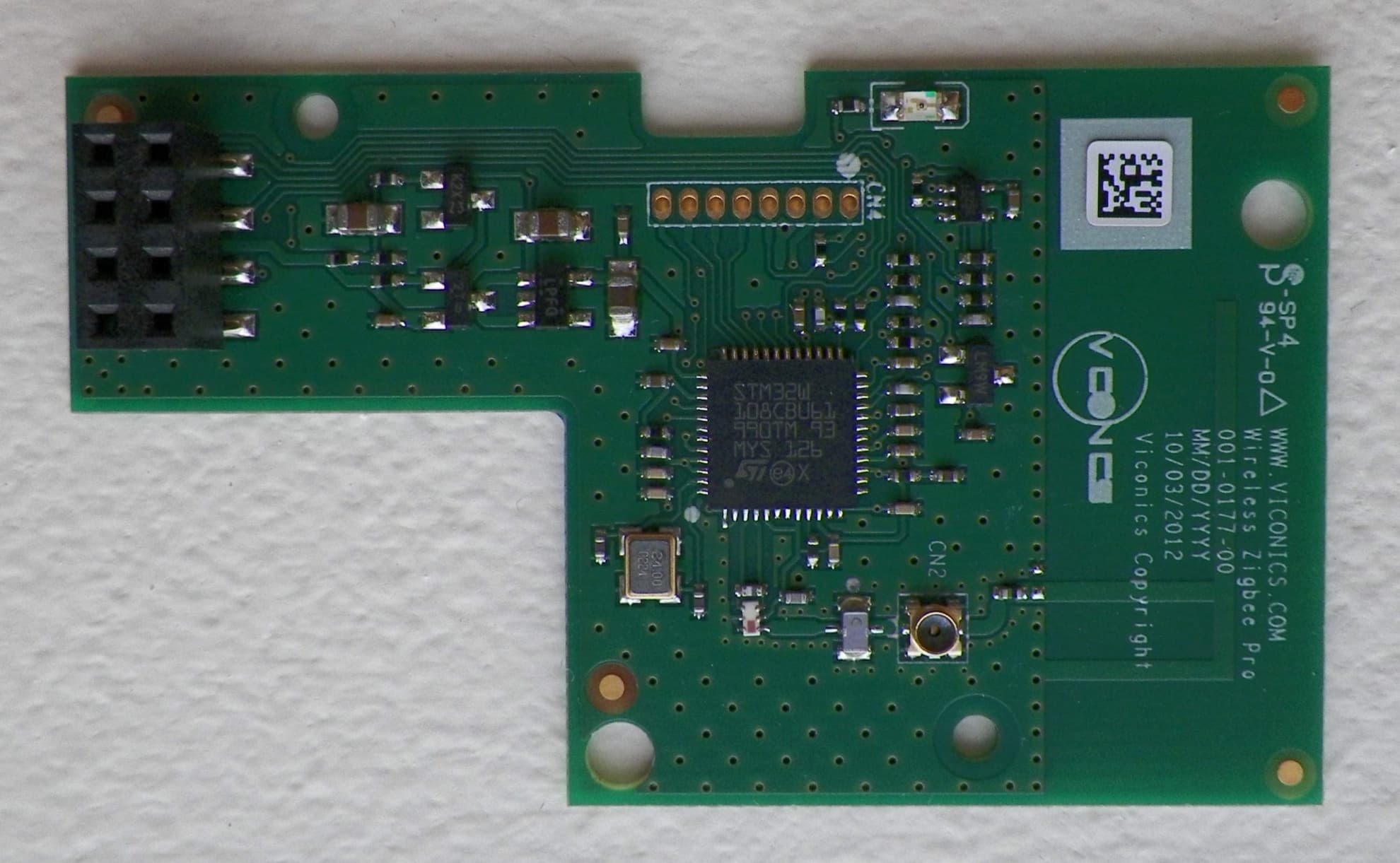
Click to zoom
Application Details
- Equipment Class
- DTS - Digital Transmission System
- Date of Grant
- Dec 13, 2012
- Application Purpose
- Original Equipment
- Date of Application
- Dec 13, 2012
- Equipment Note
- WIRELESS THERMOSTAT DATA TERMINAL
- Frequency Range
- 2405.00000000 - 2475.00000000
- Company
- Viconics Electronics Inc.
- Country
- Canada
Documents & Files
Document Text
Text extracted from the exhibit documents filed with the FCC. Open a document above to read the original.
Users Manual
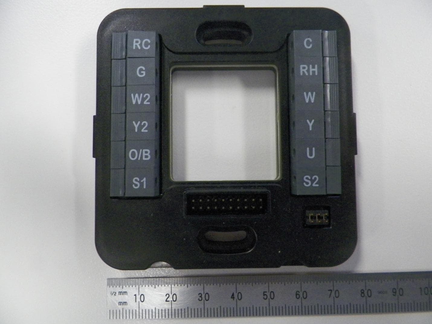
1 | VT7682S Series-Installation Guide CONTENTS Installation 2 Location 2 Installation 2 Features overview 3 Model Number 4 Terminal, Identification and Function 4 Wiring 4 Screw terminal arrangement 5 Configuring and Status Display Instructions 7 Status display 7 User Interface 8 User configuring instructions menu 8 Local keypad interface 8 Occupied setpoints adjustments 9 Installer Configuration Parameter Menu 14 Troubleshooting guide 17 All models 17 Specifications 18 Drawing & Dimensions 19 VT7682S5000W Wireless Central Manager Installa tio n G uide F o r C o m m e r c i a l H V A C A p p l i c a t i o n s December 4 th 2012 / 0 2 8-0366-R1 2 | VT7682S Series-Installation Guide INSTALLATION Remove the security screw on the bottom of Terminal Equipment Controller cover. Open unit by pulling on the bottom side of Terminal Equipment Controller (fig. 1). Remove wiring terminals from sticker. Please read the FCC ID and IC label installed in the cover upon removal of cover for the wireless products. Location 1. Should not be installed on an outside wall. 2. Must be installed away from any direct heat source. 3. Should not be installed near an air discharge grill. 4. Should not be affected by direct sun radiation. 5. Nothing should restrict vertical air circulation to the Terminal Equipment Controller. Installation 1. Swing open the Terminal Equipment Controller PCB to the left by pressing the PCB locking tabs (fig. 2). 2. Pull out cables 6” out from the wall. 3. Wall surface must be flat and clean. 4. Insert cable in the central hole of the base. 5. Align the base and mark the location of the two mounting holes on the wall. Install base in proper orientation. Arrow on base should be facing up. 6. Install anchors in the wall. 7. Insert screws in mounting holes on each side of the base (fig. 2). 8. Gently swing back the circuit board on the base and push on it until the tabs lock it. 9. Strip each wire 1/4 inch from end. 3 | VT7682S Series-Installation Guide 10. Insert each wire according to wiring diagram. 11. Gently push excess wiring back into hole (fig. 3). 12. Re-Install wiring terminals in their correct locations (fig. 3). 13. Re-install the cover (top side first) and gently push extra wire length back into the hole in the wall. 14. Install security screw. Features overview 7 day schedule (2 or 4 events). Remote outdoor sensing capability for added flexibility. System efficiency feedback. Lockable keypads for tamper proofing. No need for Terminal Equipment Controller guards. Local occupied setpoints. Sends occupancy status of building to all wireless controllers on same channel and Pan ID. Administer 60 controller units with one central master. Displays which zones are in alarm mode. Allows for setting of central occupied heating and cooling setpoints Provides alarm monitoring of all zones . When replacing an existing Terminal Equipment Controller, label the wires before removal of the Terminal Equipment Controller. Electronic controls are static sensitive devices. Discharge yourself properly before manipulating and installing the Terminal Equipment Controller. A short circuit or wrong wiring may permanently damage the Terminal Equipment Controller or the equipment. All VT7000 series Terminal Equipment Controllers are designed for use as operating controls only and are not safety devices. These instruments have undergone rigorous tests and verification prior to shipping to ensure proper and reliable operation in the field. Whenever a control failure could lead to personal injury and or loss of property, it becomes the responsibility of the user / installer / electrical system designer to incorporate safety devices (such as relays, flow switch, thermal protections, etc...) and or an alarm system to protect the entire system against such catastrophic failures. Tampering with the devices or unintended application of the devices will result in a void of warranty. 4 | VT7682S Series-Installation Guide MODEL NUMBER Part number Description VT7682S5000W Wireless Central Manager TERMINAL, IDENTIFICATION AND FUNCTION Wiring Terminal Use Terminal Identification Description 4 – RC 24Vac hot 24 V ~ Hot Power supply of controller (hot side) 5 – C 24Vac com 0 V ~ Com Power supply of controller (com side) 14 – Scom Scom Reference input for OS 15 – OS OS Outside air temperature sensor input 5 | VT7682S Series-Installation Guide Screw terminal arrangement Outdoor sensor accessories MODEL NO. DESCRIPTION S2020E1000 Outdoor temperature sensor (NEMA 4 Enclosure) S1010E1000 Outdoor temperature sensor Outdoor temperature sensors use 10K NTC thermistor. Temperature vs. resistance chart for 10 Kohm NTC thermistor ºC ºF Kohm ºC ºF Kohm ºC ºF Kohm ºC ºF Kohm ºC ºF Kohm -40 -40 324.3197 -20 -4 94.5149 0 32 32.1910 20 68 12.4601 40 104 5.3467 -39 -38 303.6427 -19 -2 89.2521 1 34 30.6120 21 70 11.9177 41 106 5.1373 -38 -36 284.4189 -18 0 84.3147 2 36 29.1197 22 72 11.4018 42 108 4.9373 -37 -35 266.5373 -17 1 79.6808 3 37 27.7088 23 73 10.9112 43 109 4.7460 -36 -33 249.8958 -16 3 75.3299 4 39 26.3744 24 75 10.4443 44 111 4.5631 -35 -31 234.4009 -15 5 71.2430 5 41 25.1119 25 77 10.0000 45 113 4.3881 -34 -29 219.9666 -14 7 67.4028 6 43 23.9172 26 79 9.5754 46 115 4.2208 -33 -27 206.5140 -13 9 63.7928 7 45 22.7861 27 81 9.1711 47 117 4.0607 -32 -26 193.9703 -12 10 60.3980 8 46 21.7151 28 82 8.7860 48 118 3.9074 -31 -24 182.2686 -11 12 57.2044 9 48 20.7004 29 84 8.4190 49 120 3.7607 -30 -22 171.3474 -10 14 54.1988 10 50 19.7390 30 86 8.0694 50 122 3.6202 -29 -20 161.1499 -9 16 51.3692 11 52 18.8277 31 88 7.7360 51 124 3.4857 -28 -18 151.6239 -8 18 48.7042 12 54 17.9636 32 90 7.4182 52 126 3.3568 -27 -17 142.7211 -7 19 46.1933 13 55 17.1440 33 91 7.1150 53 127 3.2333 -26 -15 134.3971 -6 21 43.8268 14 57 16.3665 34 93 6.8259 54 129 3.1150 -25 -13 126.6109 -5 23 41.5956 15 59 15.6286 35 95 6.5499 55 131 3.0016 -24 -11 119.3244 -4 25 39.4921 16 61 14.9280 36 97 6.2866 56 133 2.8928 -23 -9 11…
Text truncated - open the document above for the full version.
Cover Letter(s)
Viconics Technologies Inc. Tel.: (514) 321-5660 9245 Langelier Blvd., St.Léonard, Québec Canada H1P 3K9 Fax: (514) 321-4150 www.viconics.com ISO 9001 & ISO 14001 CERTIFIED Federal Communications Commission Authorization and Evaluation Division Confidentiality Request regarding application for certification of FCC ID: V95-VTP Pursuant to Sections 0.457 and 0.459 of the Commission’s Rules, we hereby request confidential treatment of information accompanying this application as outlined below: Exhibit Type File Name Schematics VTP_Schem.pdf Parts List VTP_PartsLst.pdf Block diagrams VTP_BlkDia.pdf The above materials contain trade secrets and proprietary information not customarily released to the public. The public disclosure of these materials may be harmful to the applicant and provide unjustified benefits to its competitors. The applicant understands that pursuant to Section 0.457 of the Rules, disclosure of this application and all accompanying documentation will not be made before the date of the Grant for this application. Sincerely, Paolo Primiani
Cover Letter(s)
Viconics Technologies Inc. Tel.: (514) 321-5660 9245 Langelier Blvd., St.Léonard, Québec Canada H1P 3K9 Fax: (514) 321-4150 www.viconics.com ISO 9001 & ISO 14001 CERTIFIED Dear FCC/TCB representative, We request “Limited Modular Approval” (LMA) for our proprietary VTP transceiver card, which will be installed exclusively by us, the Grantee, in products which we will design and manufacture. This device is a complete RF transmitter, i.e., it has its own reference oscillator (e.g., VCO), antenna, etc. The only connectors to the module are power supply and modulation/data inputs. Compliance with FCC RF Exposure requirements is passing and is calculated in accordance with the test report, with sufficient margin. We are aware that the end device into which an authorized module is installed is not required to obtain a new authorization for the module, however this does not preclude the possibility that some other form of authorization or testing may be required for the device in the end application. The modular transmitter does not have its own RF shielding. However, the module does not rely upon external shielding in order for all modular transmitter emissions to comply with Part 15 emissions limits. The RF transceiver is installed in VT(r)xxxxyzzzzP series of thermostats which have the same enclosure, electronics, rf module and all other electronics installed in them The modular transmitter has buffered modulation/data inputs (if such inputs are provided) to ensure that the module will comply with Part 15 requirements under conditions of excessive data rates or over- modulation. The modular transmitter must have its own power supply regulation. This is intended to ensure that the module will comply with Part 15 requirements regardless of the design of the power supplying circuitry in the device into which the module is installed. The unit is sold with the power supply it was tested with and no other supplies are certified for use at the current time. The modular transmitter complies with the antenna requirements of Section 15.203 and 15.204(c). The antenna is a PCB trace antenna. Any additional antennas will result in a Class II permissive change. The modular transmitter was tested in a VT7656B5500P Chassis which is the same enclosure type as all the other VT(r)xxxxyzzzzP chassis. This shows that the VT7656B5500P unit and the product family VT(r)xxxxyzzzzP are capable of complying with Part 15 emission limits regardless of the VT(r)xxxxyzzzzP thermostat into which it is eventually installed. The modular transmitter will be labelled with its own FCC ID number, and, the unit will be sold as it was tested. ISO 9001 & ISO 14001 CERTIFIED Internal documentation regarding the use of this module explains this requirement. As this module will be for use exclusively by the Grantee, we attest that we will retain control of this labelling and ensure this requirement is met on the end use product. The modular transmitter complies with all the specific rules or operating requirements applicable to this transmitter and we attest that we will provide adequate instructions along with the module to explain any such requirements that need to be met when this modular transmitter is incorporated into another device. A copy of these internal instructions are included in the application for equipment authorization. The modular transmitter complies with any applicable RF exposure requirements, as per the test report. The end device manual will provide specific installation and operating instructions for users, installers and other interested parties to ensure compliance, such as that ‘a minimum distance of 20cm between the antenna and any person is to maintained during operation’. As the shielding requirement is not met, we request a limited modular approval. We, the grantee attest that we will not modify the electrical or mechanical construction of the units to retain control over the emission characteristics. The product is not intended to be used inside another equipment of any kind, it will be sold and used as is in the enclosure provided by Viconics. Sincerely, Paolo Primiani
External Photos
Front (module) Back (module) External thermostat
Internal Photos
Front (module) Back (module)
Operational Description
Zigbee Pro Module Operational description The Zigbee module is a daughter board module which is installed onto a Viconics thermostat to provide a Zigbee communicating network. This network is a 2.4GHz ISM band RF signal to provide the thermostat(s) a means of communicating to a BAS (Building Automation System) and also provide communication of various data between thermostats. Below is a small description of the various blocks within the Zigbee Module. 1. SPI Communication interface The SPI communications interface is used to provide data exchange between the thermostat and the Zigbee module. This SPI interface is a bi-directional interface which provide all required information from the thermostat to be transmitted via RF to other thermostats or systems. 2. Antenna The antenna is design for a 2.4GHz RF signal to be transmitted and received to and from other thermostats or systems. 3. CPU & RF Transceiver This sections contains the STM32W108 SoC device with it’s supporting electronic components. The crystal used for the CPU is 24MHz. The MCU and the transceiver are on the same chip. The CPU communicates via the SPI interface to and from the thermostat (see SPI Communications Interface above). Power fro the SoC is received from a 3.3 LDO regulator within the power supply block. 4. Power Supply The input to the regulator is approximately 6.2Vdc provided by the thermostat power supply. The output of the power supply block basically consists of the 3.3V LDO regulator which is used to power the circuits and the Soc (MCU and Transceiver).
RF Exposure Info
Global EMCAshwani Prediction of MPE limit at a given distance Equation from page 18 of OET Bulletin 65, Edition 97-01 where:S = power density P = power input to the antenna G = power gain of the antenna in the direction of interest relative to an isotropic radi a R = distance to the center of radiation of the antenna Maximum peak output power at antenna input terminal:4.50(dBm) Maximum peak output power at antenna input terminal:2.818382931(mW) Antenna gain(typical):1(dBi) Maximum antenna gain:1.258925412(numeric) Time Averaging:100(%) Prediction distance:1(cm) Prediction frequency:2450(MHz) MPE limit for uncontrolled exposure at prediction frequency:1(mW/cm^2) Power density at prediction frequency:0.282352(mW/cm^2) Margin of compliance:-5.5(dB) This e quates to2.823515239W/m^2Complies 2 4R PG S This equates to2.823515239W/m 2Complies For informationThis equates to32.62614358 V/m Note: This device does not exceed the 60 / f (GHz) in mW limit as per FCC KDB 447498 2(a)(i), so it is allowable to be used in portable exposure conditions with no restrictions on host platforms 2 4R PG S Malhotra ator ss
Test Report
LAB REGISTRATION #6844A-2 FCC REGISTRATION #612361 Testing Laboratory Certificate #2555.01 Page 1 of 58 Report issue date: 11/21/2012 GEMC File #: GEMC-FCC-20847R1 © Glo bal EMC Inc. This test report shall not be reproduced except in full, without written approval of Glo bal EMC Inc. This report is based on GEMC Template “FCC 15 247 Rev2.” Global EMC Inc. Labs EMC & RF Test Report As per RSS 210 Issue 8:2010 & FCC Part 15 Subpart C:2011 Unlicensed Intentional Radiators on the VTP transceiver card Scott Drysdale, NCT EMC Lab Manager Global EMC Inc. 180 Brodie Dr, Unit 2 Richmond Hill, ON L4B 3K8 Canada Ph: (905) 883-3919 Testing produced for See Appendix A for full customer & EUT details . Client Viconics Technologies Product VTP transceiver card Standard(s) RSS 210 Issue 8:2010 / FCC Part 15 Subpart C 15:2011 Page 2 of 58 Report issue date: 11/21/2012 GEMC File #: GEMC-FCC-20847R1 © Glo bal EMC Inc. This test report shall not be reproduced except in full, without written approval of Global EMC Inc. Table of Contents Table of Contents ................................................................................................................... 2 Report Scope .......................................................................................................................... 3 Summary ................................................................................................................................ 4 Test Results Summary ....................................................................................................... 5 Justifications, Descriptions, or Deviations......................................................................... 7 Applicable Standards, Specifications and Methods ........................................................... 8 Sample calculation(s) ......................................................................................................... 9 Document Revision Status ................................................................................................. 9 Definitions and Acronyms ................................................................................................... 10 Testing Facility .................................................................................................................... 11 Calibrations and Accreditations ....................................................................................... 11 Testing Environmental Conditions and Dates ................................................................. 12 Detailed Test Results Section .............................................................................................. 13 Power Line Conducted Emissions ................................................................................... 14 Radiated Emissions .......................................................................................................... 20 6dB Bandwidth of Digitally Modulated Systems ............................................................ 36 Maximum Peak Envelope Conducted Power - DM ......................................................... 42 Power Spectral Density - DM .......................................................................................... 48 Appendix A – EUT Summary .............................................................................................. 52 Appendix B – EUT and Test Setup Photographs................................................................. 53 Client Viconics Technologies Product VTP transceiver card Standard(s) RSS 210 Issue 8:2010 / FCC Part 15 Subpart C 15:2011 Page 3 of 58 Report issue date: 11/21/2012 GEMC File #: GEMC-FCC-20847R1 © Glo bal EMC Inc. This test report shall not be reproduced except in full, without written approval of Global EMC Inc. Report Scope This report addresses the EMC verification testing and test results of the VTP Transceiver card, herein referred to as EUT (Equipment Under Test) performed at Global EMC Labs. The EUT was tested for compliance against the following standards: RSS 210 Issue 8:2010 / FCC Part 15 Subpart C 15:2011 Test procedures, results, justifications, and engineering considerations, if any, follow later in this report. The results contained in this report relate only to the item(s) tested. This report does not imply product endorsement by A2LA or any other accreditation agency, any government, or Global EMC Inc. Opinions/interpretations expressed in this report, if any, are outside the scope of Global EMC Inc accreditation. Any opinions expressed do not necessarily reflect the opinions of Global EMC Inc, unless otherwise stated. Client Viconics Technologies Product VTP transceiver card Standard(s) RSS 210 Issue 8:2010 / FCC Part 15 Subpart C 15:2011 Page 4 of 58 Report issue date: 11/21/2012 GEMC File #: GEMC-FCC-20847R1 © Glo bal EMC Inc. This test report shall not be reproduced except in full, without written approval of Global EMC Inc. Summary The results contained in this report relate only to the item(s) tested. EUT FCC Certification #, FCC ID: V95-VTP EUT Industry Canada Certification #, IC: 7591A-VTP EUT Passed all tests performed. Yes (see test results summary) Tests conducted by Scott Drysdale Client Viconics Technologies Product VTP transceiver card Standard(s) RSS 210 Issue 8:2010 / FCC Part 15 Subpart C 15:2011 Page 5 of 58 Report issue date: 11/21/2012 GEMC File #: GEMC-FCC-20847R1 © Glo bal EMC Inc. This test report shall not be reproduced except in full, without written approval of Global EMC Inc. Test Results Summary Standard/Method Description Class/Limit Result FCC 15.203 Antenna Requirement Unique Pass See Justification FCC 15.205 RSS 210 (Table 1) Restricted Bands for intentional operation QuasiPeak Average Pass FCC 15.207 Power line conducted emissions QuasiPeak Average Pass FCC 15.209 RSS-210 (Table 2) Spurious Radiated emissions QuasiPeak Average Pass FCC 15.247(a)2 RSS-210 A8.2(a) 6 dB Bandwidth > 500 kHz Pass FCC 15.247(b)…
Text truncated - open the document above for the full version.
Test Setup Photos
Radiated Emissions – Below 30 MHz Radiated Emissions – 30 MHz to 1 GHz Radiated Emissions – Above 1 GHz Antenna Port Conducted Emissions
Contact Information
Applicant
Emmanuel Stathopoulos(Certification)
Test Firm
TUV SUD CANADA (Gormley)William (Mac) Elliott
[email protected]813-284-2736
Technical Specifications
| # | Rule Parts | Frequency Range | Power Output |
|---|---|---|---|
| 1 | 15C | 2.40 GHz - 2.48 GHz | 3.00 mW |
Other Applications from Viconics Electronics Inc.
V95-WIS
Aug 17, 2015Thermostat
Equipment Class
DTS - Digital Transmission System
V95-VWAP
Dec 18, 2013Wireless door and window switch
Equipment Class
DTS - Digital Transmission System
V95-VWA
May 11, 2011WIRELESS SWITCH ACCESSORY FOR THERMOSTAT APPLICATIONS
Equipment Class
DTS - Digital Transmission System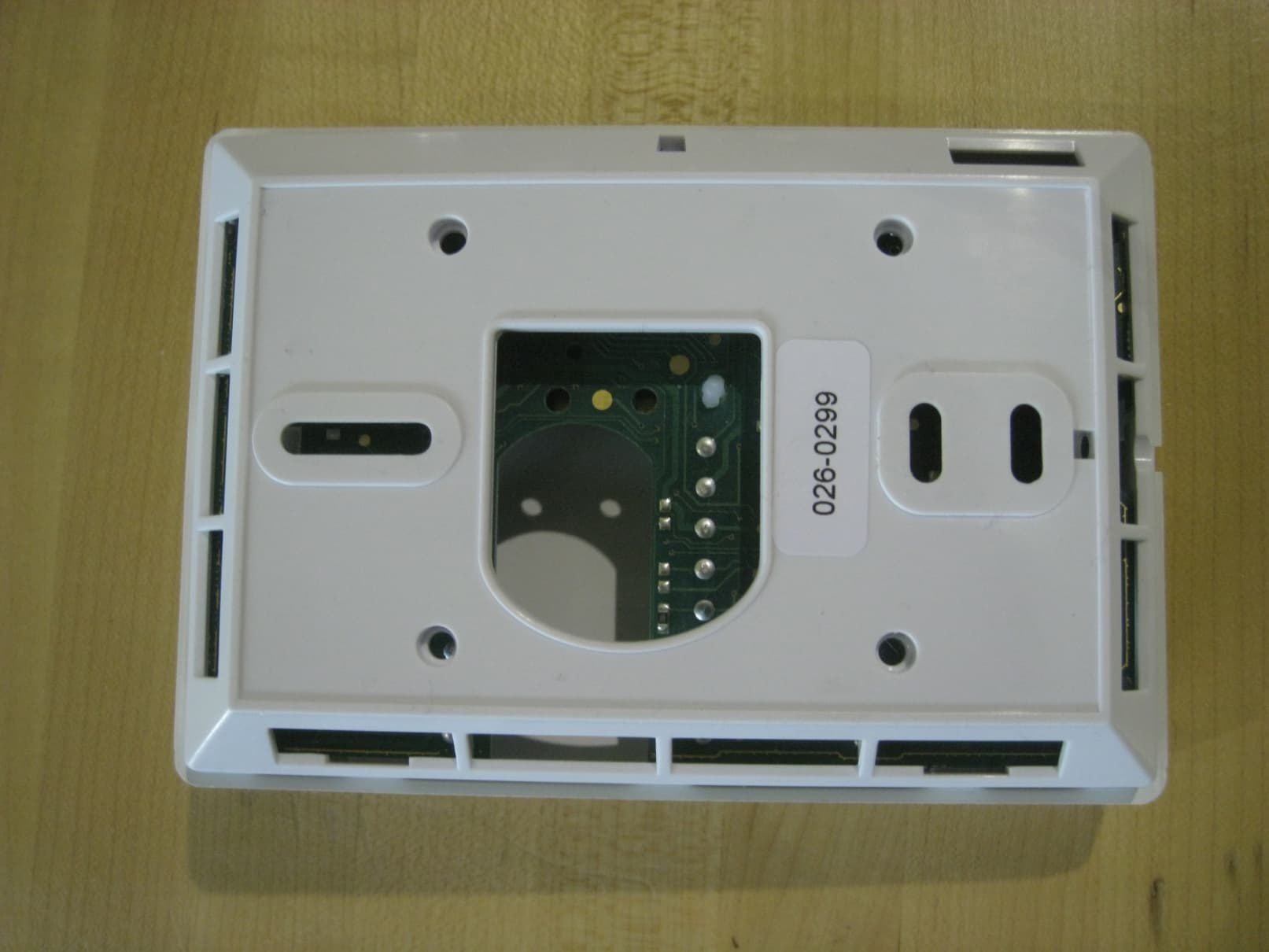
V95-VTR
Jun 27, 2010WIRELESS THERMOSTAT/DATA TERMINAL
Equipment Class
DTS - Digital Transmission System