V95-VTRWIRELESS THERMOSTAT/DATA TERMINAL
Viconics Electronics Inc.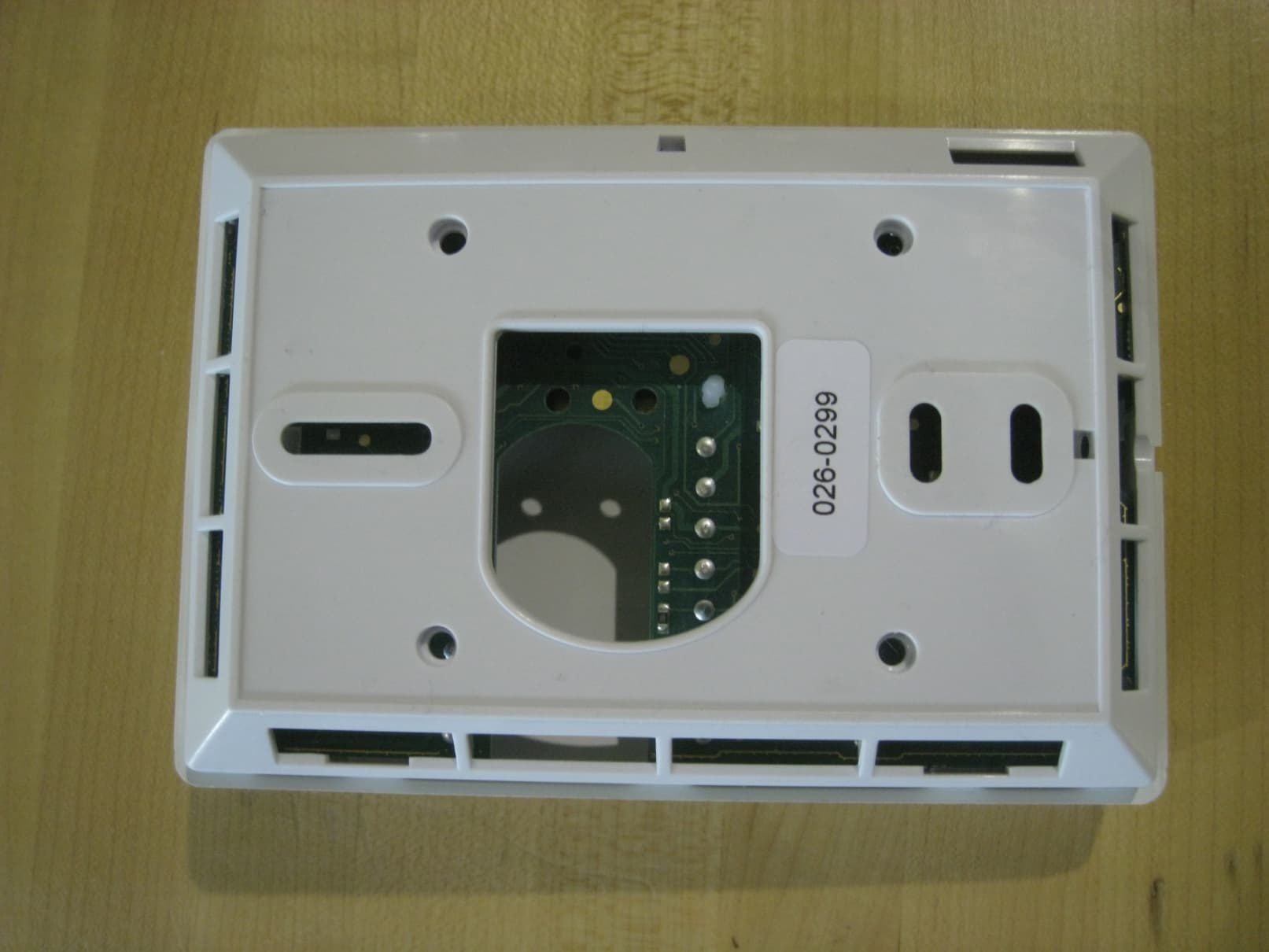
Click to zoom
Application Details
- Equipment Class
- DTS - Digital Transmission System
- Date of Grant
- Jun 27, 2010
- Application Purpose
- Original Equipment
- Date of Application
- Jun 23, 2010
- Equipment Note
- WIRELESS THERMOSTAT/DATA TERMINAL
- Frequency Range
- 2405.00000000 - 2480.00000000
- Company
- Viconics Electronics Inc.
- Country
- Canada
Documents & Files
Document Text
Text extracted from the exhibit documents filed with the FCC. Open a document above to read the original.
Users Manual
PIR Ready VTR7300 Series Terminal Equipment Controllers For Commercial and Lodging HVAC Fan Coil Applications (Issue Date: March 29, 2010 – 028-0298_R0) Product overview The VTR73XX Series Fan Coil Terminal Equipment Controller used in conjunction with the VC3000 Series Line Voltage Switching Relay Packs is specifically designed for fan coil control applications. They can be used both for new or retrofit applications. In retrofit applications, they can re-use the existing wires between the old line voltage switching thermostat and the fan coil thus saving on the installation of any new wires. Stand-alone and network operation are available. The VTR73XX Series Fan Coil Terminal Equipment Controller features a backlit LCD display with dedicated function menu buttons for simple operation. Accurate temperature control is achieved due to the product’s PI proportional control algorithm, which virtually eliminates temperature offset associated with traditional, differential- based Terminal Equipment Controllers. All models feature configurable System and Fan button functions to meet all possible applications The VTR73XX Terminal Equipment Controllers are powered and communicate with the associated VC3000 Series Transformer Relay Pack(s) using only 3 wires. 2 types of interfaces for the user can be ordered. The VC73x5 models are typically used for hotel and lodging applications where the middle button of the interface is for the user to select the local displayed scale in ºF or ºC. The VC73x0 models are typically used for commercial and institution applications where the middle button of the interface is defined for the local unoccupied override function. The VTR73XX Terminal Equipment Controllers are also compatible with the new Viconics PIR cover accessories. Terminal Equipment Controllers equipped with a PIR cover provide advanced active occupancy logic, which will automatically switch occupancy levels from Occupied to Stand-By and Unoccupied as required by local activity being present or not. This advanced occupancy functionality provides advantageous energy savings during occupied hours without sacrificing occupant comfort. All Terminal Equipment Controllers can be ordered with or without a factory installed PIR cover ( see ordering notes below ). The compatible VC3000 Series Line Voltage Switching Transformer Relay Pack(s) operate as slave unit(s) under the control of a single master VTR73XX Terminal Equipment Controller. A single VTR73XX Terminal Equipment Controller can control up to 10 VC3000 Series Relay Pack. The VC3000 Series Relay Packs are line-powered units. They locally contain all the relay outputs for fan switching and valve control. Models are also available for extra monitoring / control inputs of the Fan Coil Units. The additional following documents are available at: www.viconics.com • PIR Hospitality application information and examples, are available on document: APP-HOSPITALITY-PIR-VTR73-Guide-Exx • HVAC Fan Coil application information and examples, are available on document: APP-VTR7300-PIR-Exx • Information on installation of the Transformer Relay Pack (VC3000E), is available on document LIT-VC3000-Exx • PIR cover installation information is available on document: PIR Cover Installation-Exx • Information on the BACnet models (VTR73xxX5x00B), is available on document ITG-VTR73-PIR-BAC-Exx • Information on the Wireless models (VTR3xxX5x00W), is available on documents: ITG-VWG-40-BAC-Exx and MAN Wireless Stat Driver Guide-Exx VTR73XXA models available Viconics part number VTR7300A5x00(x) VTR7350A5x00(x) VTR7305A5x00(x) VTR7355A5x00(x) Primary market User interface definition Commercial and institution applications Hotels and lodging applications On board %RH sensor For dehumidification strategy None Yes None Yes Ordering Information Notes: The (X) at the end of the model number represents available communication options: • X = none for Stand-alone • X = B for BACnet MS-TP • X = W for Wireless The Terminal Equipment Controllers can be ordered with a factory installed PIR cover. Please use (5500) extension instead of the (5000) only extension. The Terminal Equipment Controllers ordered without a PIR cover can be retrofitted with a separate PIR accessory cover afterwards if required. Ordering examples: • A VTR7305AW5500B is for a wall mounted Terminal Equipment Controller with a hotel / lodging interface with a factory mounted PIR cover and an MS-TP BACnet communication interface. • A VTR7350A5000W is for a wall mounted Terminal Equipment Controller with a commercial / institution interface and a wireless communication interface. The Terminal Equipment Controller can be retrofitted with a separate PIR accessory cover afterwards if required. 028-0298_R0_LIT-VTR7300-PIR-E00.doc www.viconics.com / [email protected] VTR73x5X Lodging VTR73x0X Commercial 2 Operation overview The VC3xxxX Series Line Voltage Switching Transformer Relay Pack(s) operate as slave unit(s) under the control of a single master VTR73xxA Terminal Equipment Controller. Fan operation can be configured and wired for the following: o 3 Speed configuration using 3 fan relays ( Low – Med - High ) o 2 Speed configuration using 2 fan relays ( Low - High ) o 3 Speed configuration with Auto fan speed mode using 3 fan relays ( Low – Med - High ) o 2 Speed configuration with Auto fan speed mode using 2 fan relays ( Low - High ) o Single fan speed configuration. The VTR7300 Controller can be configured for typical 2 or 4 pipe heating / cooling FCU applications. 2 or 4 pipe only operation can be configured and wired for the following: o Cooling only o Heating only o Cooling / Heating with network or local auto changeover 2 or 4 pipe only with electric reheat can be configured and wired for the following: o Cooling only o Heating only o Cooling / Heating with network or local auto changeover o On-Off electric reheat only o Cooling with On-Off or modulating Vdc pulsed electric reheat ( model dependent ) o Heating with On…
Text truncated - open the document above for the full version.
Cover Letter(s)
Viconics Electronics Inc. Tel.: (514) 321-5660 9245 Langelier Blvd., St.Léonard, Québec Canada H1P 3K9 Fax: (514) 321-4150 www.viconics.com ISO 9001 & ISO 14001 CERTIFIED Dear FCC/TCB representative, We request “Limited Modular Approval” (LMA) for our proprietary VTR7355A5500W transceiver card, which will be installed exclusively by us, the Grantee, in products which we will design and manufacture. This device is a complete RF transmitter, i.e., it has its own reference oscillator (e.g., VCO), antenna, etc. The only connectors to the module are power supply and modulation/data inputs. Compliance with FCC RF Exposure requirements is passing and is calculated in accordance with the test report, with sufficient margin. We are aware that the end device into which an authorized module is installed is not required to obtain a new authorization for the module, however this does not preclude the possibility that some other form of authorization or testing may be required for the device in the end application. The modular transmitter does not have its own RF shielding. However, the module does not rely upon external shielding in order for all modular transmitter emissions to comply with Part 15 emissions limits. The RF transceiver is installed in VTRxxxxyzzzzW series of thermostats which have the same enclosure, electronics, rf module and all other electronics installed in them The modular transmitter has buffered modulation/data inputs (if such inputs are provided) to ensure that the module will comply with Part 15 requirements under conditions of excessive data rates or over- modulation. The modular transmitter must have its own power supply regulation. This is intended to ensure that the module will comply with Part 15 requirements regardless of the design of the power supplying circuitry in the device into which the module is installed. The unit is sold with the power supply it was tested with and no other supplies are certified for use at the current time. The modular transmitter complies with the antenna requirements of Section 15.203 and 15.204(c). The antenna is a PCB trace antenna. Any additional antennas will result in a Class II permissive change. The modular transmitter was tested in a VTR7355A5500W Chassis which is the same enclosure type as all the other VTRxxxxyzzzzW chassis. This shows that the VTR7355A5500W unit and the product family VTRxxxxyzzzzW are capable of complying with Part 15 emission limits regardless of the VTRxxxxyzzzzW thermostat into which it is eventually installed. The modular transmitter will be labelled with its own FCC ID number, and, the unit will be sold as it was tested. Internal be for us this requ rules or and we a requirem copy of modula r end devi other int antenna As the s that we w emission will be s Sincerely , Paolo Pri m documentat se exclusive uirement is m operating re attest that we ments that ne these interna r transmitter ice manual w terested part and any per hielding req will not mod n characteris sold and used , miani tion regardin ly by the Gr met on the en equirements e will provid eed to be me al instruction complies w will provide ties to ensure rson is to ma quirement is n dify the elect stics. The pro d as is in the ISO 900 ng the use of rantee, we at nd use produ applicable to de adequate et when this m ns are includ ith any appli specific inst e compliance aintained dur not met, we trical or mec oduct is not e enclosure p 01 & ISO 1400 fthis module test that we uct. The mod o this transm instructions modular tran ded in the ap icable RF ex tallation and e, such as th ring operatio request a lim chanical con intended to provided by 01 CERTIFIE e explains th will retain c dular transm mitter along with t nsmitter is in pplication for xposure requ d operating in hat ‘a minimu on’. mited modul nstruction of be used insi Viconics. ED his requireme control of thi mitter complie the module t ncorporated r equipment uirements, as nstructions f um distance lar approval. the units to de another e ent. As this m is labelling a es with all th to explain an into another authorizatio s per the test for users, ins of 20cm bet . We, the gra retain contro equipment of module will and ensure he specific ny such r device. A on. The t report. The stallers and tween the antee attest ol over the f any kind, itt
External Photos
Typical Host (Front) Typical Host (Back)
Internal Photos
Wireless Card – Top Wireless card – Bottom Host Top Host Top (wireless card removed) Host Bottom
Operational Description
Zigbee Module Operational description The Zigbee module is a daughter board module which is installed onto a Viconics thermostat to provide a Zigbee communicating network. This network is a 2.4GHz ISM band RF signal to provide the thermostat(s) a means of communicating to a BAS (Building Automation System) and also provide communication of various data between thermostats. Below is a small description of the various blocks within the Zigbee Module. 1. SPI Communication interface The SPI communications interface is used to provide data exchange between the thermostat and the Zigbee module. This SPI interface is a bi-directional interface which provide all required information from the thermostat to be transmitted via RF to other thermostats or systems. 2. Antenna The antenna is design for a 2.4GHz RF signal to be transmitted and received to and from other thermostats or systems. 3. CPU & RF Transceiver This sections contains the CC2430 SoC device with it’s supporting electronic components. The crystals used for the CPU are of 32MHz and 32KHz. The MCU and the transceiver are on the same chip. The CPU communicates via the SPI interface to and from the thermostat (see SPI Communications Interface above). Power fro the SoC is received from a 3.3 LDO regulator within the power supply block. 4. Power Supply The input to the regulator is approximately 6.2Vdc provided by the thermostat power supply. The output of the power supply block basically consists of the 3.3V LDO regulator which is used to power the circuits and the Soc (MCU and Transceiver).
RF Exposure Info
Global EMC Prediction of MPE limit at a given distance Equation from page 18 of OET Bulletin 65, Edition 97-01 where:S = power density P = power input to the antenna G = power gain of the antenna in the direction of interest relative to an isotropic radi a R = distance to the center of radiation of the antenna Maximum peak output power at antenna input terminal:-4.00(dBm) Maximum peak output power at antenna input terminal:0.398107171(mW) Antenna gain(typical):2(dBi) Maximum antenna gain:1.584893192(numeric) Time Averaging:100(%) Prediction distance:1(cm) Prediction frequency:2450(MHz) MPE limit for uncontrolled exposure at prediction frequency:1(mW/cm^2) Power density at prediction frequency:0.050210(mW/cm^2) Margin of compliance:-13.0(dB) This e quates to0.502099901W/m^2Complies 2 4R PG S π = This equates to0.502099901W/m 2Complies For informationThis equates to13.75833067 V/m Note: This device does not exceed the 60 / f (GHz) in mW limit as per FCC KDB 447498 2(a)(i), so it is allowable to be used in portable exposure conditions with no restrictions on host platforms 2 4R PG S π = ator ss
Test Report
LAB REGISTRATION #6844A-1 FCC REGISTRATION #612361 Page 1 of 63 Report issue date: 6/18/2010 GEMC File #:GEMC-FCC-19650R2 © Global EMC Inc. This test report shall not be reproduced except in full, without written approval of Global EMC Inc. This report is based on GEMC Template “FCC 15 247 Rev2.” Global EMC Inc. Labs EMC & RF Test Report As per RSS 210 Issue 7:2007 & FCC Part 15 Subpart C:2010 Unlicensed Intentional Radiators on the VTR7355A5500W Terminal Equipment Controller Scott Drysdale, Narte Certified Technician EMC Lab Manager Global EMC Inc. 180 Brodie Dr, Unit 2 Richmond Hill, ON L4B 3K8 Canada Ph: (905) 883-3919 Testing produced for See Appendix A for full customer & EUT details . Client Viconics Product VTR7355A5500W Terminal Equipment Controller Standard(s) RSS 210 Issue 7:2007 / FCC Part 15 Subpart C 15:2010 Page 2 of 63 Report issue date: 6/18/2010 GEMC File #: GEMC-FCC-19650R2 © Global EMC Inc. This test report shall not be reproduced except in full, without written approval of Global EMC Inc. Table of Contents Table of Contents ................................................................................................................... 2 Report Scope .......................................................................................................................... 3 Summary ................................................................................................................................ 4 Test Results Summary ....................................................................................................... 5 Justifications, Descriptions, or Deviations......................................................................... 6 Applicable Standards, Specifications and Methods ........................................................... 7 Sample calculation(s) ......................................................................................................... 8 Document Revision Status ................................................................................................. 8 Definitions and Acronyms ..................................................................................................... 9 Testing Facility .................................................................................................................... 10 Calibrations and Accreditations ....................................................................................... 10 Testing Environmental Conditions and Dates ................................................................. 11 Detailed Test Results Section .............................................................................................. 12 Power Line Conducted Emissions ................................................................................... 13 Spurious Radiated Emissions / 20 dBc Requirement ...................................................... 20 Maximum Peak Envelope Conducted Power .................................................................. 37 Maximum Permissible Exposure ..................................................................................... 41 6dB Bandwidth of Digitally Modulated Systems ............................................................ 43 Power Spectral Density .................................................................................................... 49 Appendix A – EUT Summary.............................................................................................. 55 Appendix B – EUT and Test Setup Photographs................................................................. 56 Client Viconics Product VTR7355A5500W Terminal Equipment Controller Standard(s) RSS 210 Issue 7:2007 / FCC Part 15 Subpart C 15:2010 Page 3 of 63 Report issue date: 6/18/2010 GEMC File #: GEMC-FCC-19650R2 © Global EMC Inc. This test report shall not be reproduced except in full, without written approval of Global EMC Inc. Report Scope This report addresses the EMC verification testing and test results of the VTR7355A5500W Terminal Equipment Controller, herein referred to as EUT (Equipment Under Test) performed at Global EMC Labs. The EUT was tested for compliance against the following standards: RSS 210 Issue 7:2007 / FCC Part 15 Subpart C 15:2010 Test procedures, results, justifications, and engineering considerations, if any, follow later in this report. The results contained in this report relate only to the item(s) tested. This report does not imply product endorsement by A2LA or any other accreditation agency, any government, or Global EMC Inc. Opinions/interpretations expressed in this report, if any, are outside the scope of Global EMC Inc accreditation. Any opinions expressed do not necessarily reflect the opinions of Global EMC Inc, unless otherwise stated. Client Viconics Product VTR7355A5500W Terminal Equipment Controller Standard(s) RSS 210 Issue 7:2007 / FCC Part 15 Subpart C 15:2010 Page 4 of 63 Report issue date: 6/18/2010 GEMC File #: GEMC-FCC-19650R2 © Global EMC Inc. This test report shall not be reproduced except in full, without written approval of Global EMC Inc. Summary The results contained in this report relate only to the item(s) tested. EUT FCC Certification #, FCC ID: V95-VTR EUT Industry Canada Certification #, IC: 7591A-VTR EUT Passed all tests performed. Yes (see test results summary) Tests conducted by Scott Drysdale Client Viconics Product VTR7355A5500W Terminal Equipment Controller Standard(s) RSS 210 Issue 7:2007 / FCC Part 15 Subpart C 15:2010 Page 5 of 63 Report issue date: 6/18/2010 GEMC File #: GEMC-FCC-19650R2 © Global EMC Inc. This test report shall not be reproduced except in full, without written approval of Global EMC Inc. Test Results Summary Standard/Method Description Class/Limit Result FCC 15.203 Antenna Requirement Unique Pass See Justification FCC 15.205 RSS 210 (Table 1) Restricted Bands for intentional operation QuasiPeak Average Pass FCC 15.207 Power line conducted emissions QuasiPeak Avera…
Text truncated - open the document above for the full version.
Test Setup Photos
Radiated Emissions Photo 1 (Grantee’s Host Configuration) Radiated Emissions Photo 2 (Grantee’s Host Configuration) Radiated Emissions Photo 3 (Grantee’s Host Configuration) Power Line Conducted Emissions (G rantee’s Host Configuration) Note in all cases, the plastic cove r was removed and deemed not to have any impact on the test results.
Contact Information
Applicant
Emmanuel Stathopoulos(Certification)
Test Firm
Global EMC Inc.Scott Drysdale
Technical Specifications
| # | Rule Parts | Frequency Range | Power Output |
|---|---|---|---|
| 1 | 15C | 2.40 GHz - 2.48 GHz | 500.00 µW |
Other Applications from Viconics Electronics Inc.
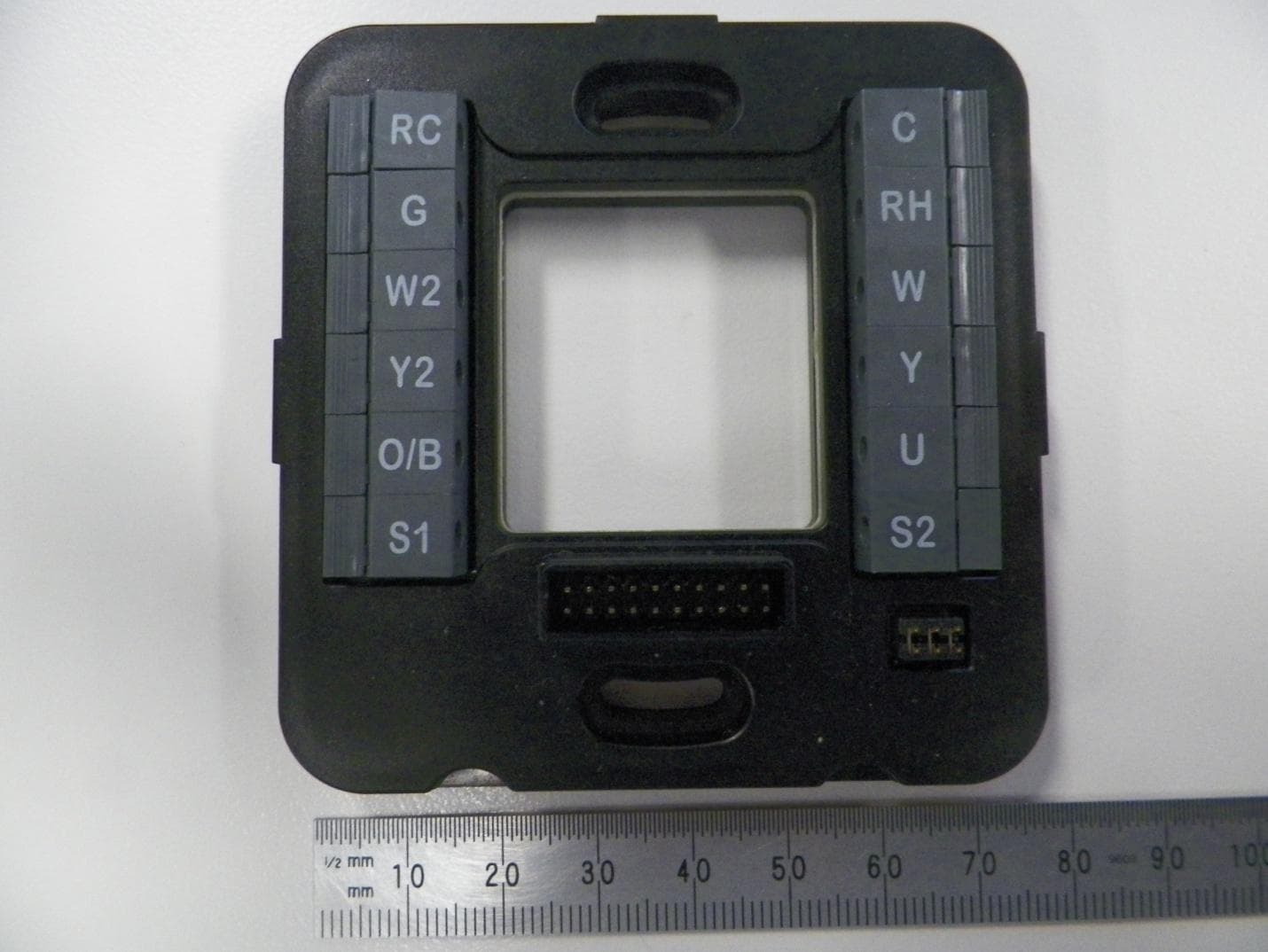
V95-WIS
Aug 17, 2015Thermostat
Equipment Class
DTS - Digital Transmission System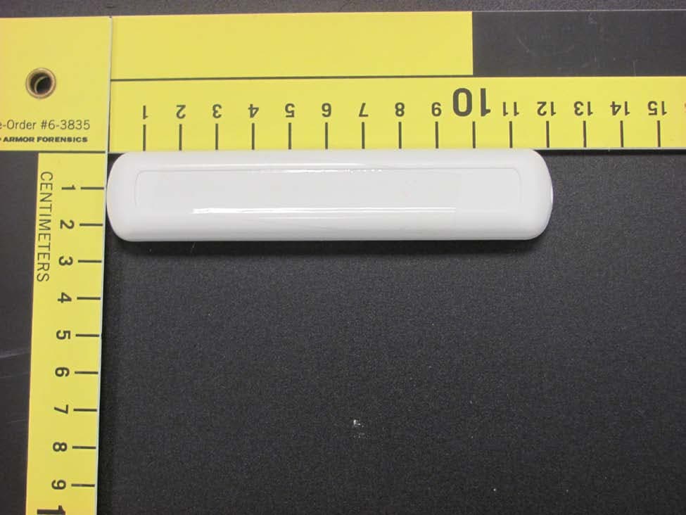
V95-VWAP
Dec 18, 2013Wireless door and window switch
Equipment Class
DTS - Digital Transmission System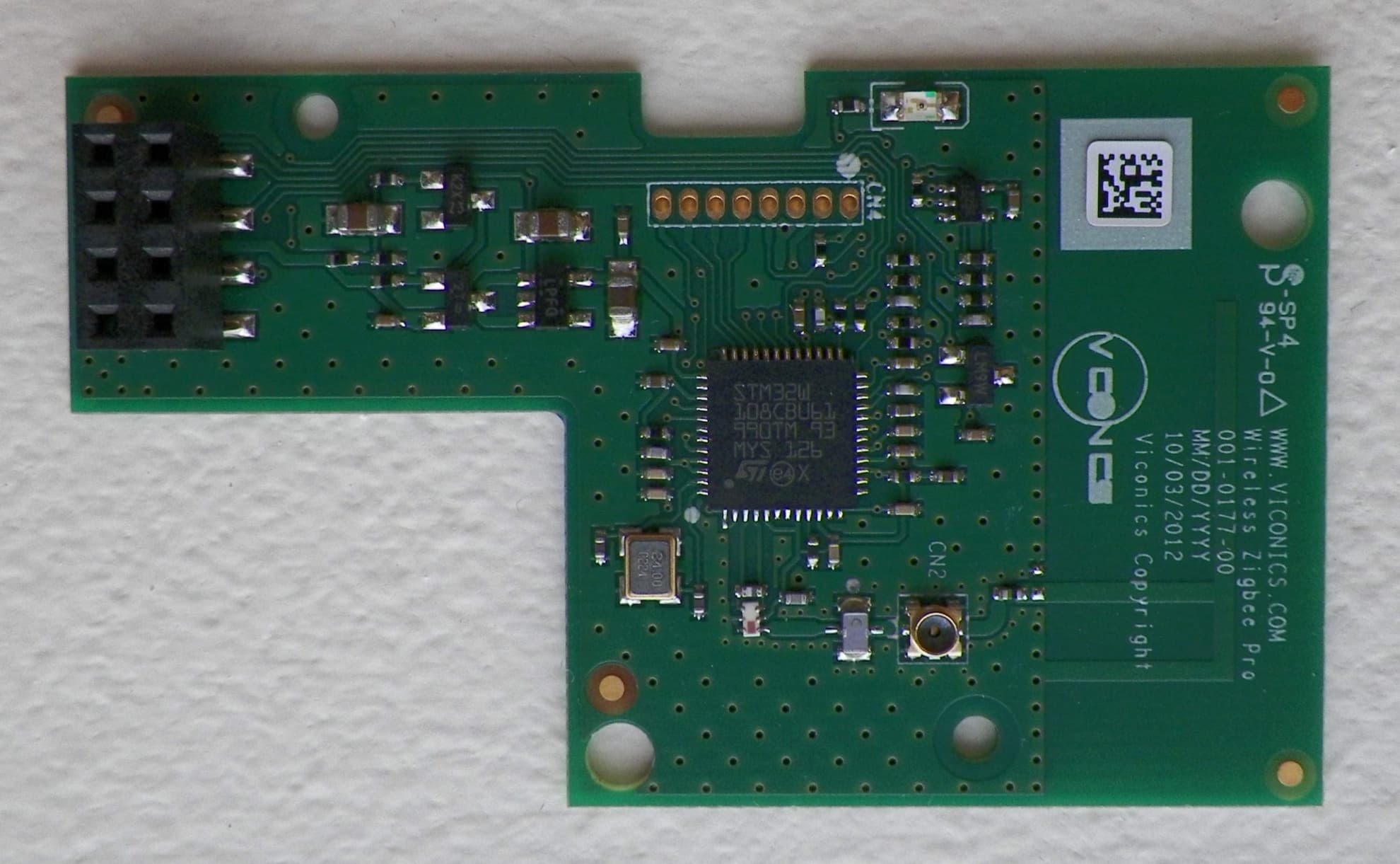
V95-VTP
Dec 13, 2012WIRELESS THERMOSTAT DATA TERMINAL
Equipment Class
DTS - Digital Transmission System
V95-VWA
May 11, 2011WIRELESS SWITCH ACCESSORY FOR THERMOSTAT APPLICATIONS
Equipment Class
DTS - Digital Transmission System