V95-WISThermostat
Viconics Electronics Inc.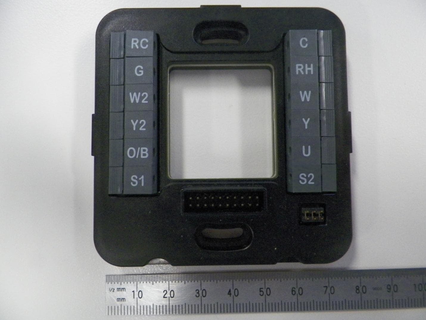
Click to zoom
Application Details
- Equipment Class
- DTS - Digital Transmission System
- Date of Grant
- Aug 17, 2015
- Application Purpose
- Original Equipment
- Date of Application
- Aug 17, 2015
- Equipment Note
- Thermostat
- Frequency Range
- 2405.00000000 - 2475.00000000
- Company
- Viconics Electronics Inc.
- Country
- Canada
Documents & Files
Document Text
Text extracted from the exhibit documents filed with the FCC. Open a document above to read the original.
Users Manual
Insert marketing spiel here. Wiser Air ™ Thermostat Technical Data Sheet Wiser Air Room Controller Features AT A GLANCE Custom design Marketing Stuff Here Options and accessories Marketing Stuff Here 2 Marketing Stuff Here Introduction Marketing Stuff Here Application specific and programmable Marketing Stuff Here Touch screen with customizable user experience Marketing Stuff Here Selectable languages Marketing Stuff Here Optional passive infrared motion sensor Marketing Stuff Here Product Highlights Marketing Stuff Here Supported Networking Protocols Marketing Stuff Here Integration to Schneider Electric Systems Marketing Stuff Here Architects can custom match styling to decor Marketing Stuff Here Models Black White Wiser Air Room Controller Features 3 6 Wiser Air Specifications Dimensions - Main Unit 10cm/4in (H) x 10cm/4in (W) x 3cm/1.2in (D) Dimensions - Trim Plate 12cm/4.8in (H) x 16cm/6.3in (W) x 0.3cm/0.1in (D) Power Requirements Input: 24Vac ±15%, 50/60Hz Device consumption: 6 VA Maximum rating: 100 VA, 4.17 A Class 2 circuits only Output Ratings Maximum total output: 94 VA Relay rating: 24 Vac 50/60Hz, 1.0 Amp., in-rush = 3.0 Amp; pins G, W, W2, Y, Y2, U, O/B Class 2 circuits only Operating Conditions 0 °C - 50 °C ( 32 °F - 122 °F ) 0% - 75% R.H. non-condensing Storage Conditions -30 °C - 50 °C ( -22 °F - 122 °F ) 0% - 75% R.H. non-condensing Indoor, Dry, Pollution Degree 2 Temperature Sensor Resolution ± 0.1 °C ( ± 0.2 °F ) Temperature Control Accuracy ±0.5 ° C ( ± 0.9 °F )@ 21 °C ( 70 °F ) typical calibrated Humidity Sensor and Calibration Single point calibrated bulk polymer type sensor Humidity Sensor Precision Reading range from 10-90 % R.H. non-condensing 10 to 20% precision: 10% 20% to 80% precision: 5% 80% to 90% precision: 10% Humidity Sensor Stability Less than 1.0 % yearly (typical drift) Dehumidification Setpoint Range 30% - 95% R.H. Occ, Stand-By and Unocc Cooling Setpoint Range 12.0 - 37.5 °C ( 54 - 100 °F ) Occ, Stand-By and Unocc Heating Setpoint Range 4.5 °C - 32 °C ( 40 °F - 90 °F ) Room and Outdoor Air Temperature Display Range -40 °C - 50 °C ( -40 °F - 122 °F ) Proportional Band for Room Temperature control Cooling and Heating: Default: 1.8°C ( 3.2°F ) Remote Temperature Sensor Require- ments 10 K NTC type 2 thermistor Wire Gauge 18 - 22 AWG Approximate Shipping Weight 0.34 kg (0.75 lb) Safety Standards All Models LVD Directive 2006/95/EC EN 60730-1 UL 873, UL 916 CSA C22.2 No. 24-93 EMC Standards All Models EMC Directive 2004/108/EC EN 60730-1 FCC 15 Subpart B ICES-003 Radio Standards (Wireless Models) R&TTE Directive 1999/5/EC ETSI EN 300 328 V1.8.1 ETSI EN 301 489-1 V1.9.2 ETSI EN 301 328 V1.8.1 FCC 15 Subpart C RSS 210 THIS DEVICE COMPLIES WITH PART 15 OF THE FCC RULES. OPERATION IS SUBJECT TO THE FOLLOWING TWO CONDITIONS: (1) THIS DEVICE MAY NOT CAUSE HARMFUL INTERFERENCE, AND (2) THIS DEVICE MUST ACCEPT ANY INTERFERENCE RECEIVED, INCLUD- ING INTERFERENCE THAT MAY CAUSE UNDESIRED OPERATION. Specifications Check with your local government for instruction on disposal of these products. Dimensions 7.5cm (3”) 7.8cm (3.1”) 3cm (1.2”) RC G W2 Y2 O/B S1 C RH W Y U S2 10cm (4”) 10cm (4”) © 2015 Schneider Electric. All rights reserved. 7 Regulatory Compliance This device complies with Part 15 of the FCC Rules. Operation is subject to the following two conditions: • this device may not cause harmful interference • this device must accept any interference received, including interference that may cause undesired operation. This device complies with Industry Canada licence-exempt RSS standard(s). Operation is subject to the following two conditions: • this device may not cause interference • this device must accept any interference, including interference that may cause undesired operation of the device. Changes or modifications not approved by the manufacturer could void the user’s authority to operate the equipment. This equipment complies with FCC radiation exposure limits set forth for an uncontrolled environment. In order to avoid the possibility of exceeding the FCC radio frequency exposure limits, human proximity to the antenna shall not be less than 20cm during normal operation. This equipment complies with IC RSS-102 radiation exposure limits set forth for an uncontrolled environment. This equipment should be installed and operated with minimum distance 20cm between the radiator & your body. Electrical equipment should be installed, operated, serviced, and maintained only by qualified personnel. No responsibility is assumed by Schneider Electric for any consequences arising out of the use of this material. Schneider Electric www.schneider-electric.com/buildings SDS-WISER WISER AIR May 2015
Cover Letter(s)
Request for Confidentiality Date: _2015.08.05_ Subject: Confidentiality Request for: _____V95-WIS Pursuant to FCC 47 CRF 0.457(d) and 0.459 and IC RSP-100, Section 6.4, the applicant requests that a part of the subject FCC application be held confidential. Type of Confidentiality Requested Exhibit Short Term Permanent Block Diagrams Short Term External Photos Short Term Permanent* 2 Internal Photos Short Term Permanent Operation Description/Theory of Operation Short Term Permanent Parts List & Placement/BOM Short Term Permanent Tune-Up Procedure Short Term Permanent Schematics Short Term Test Setup Photos Short Term Permanent* 3 User’s Manual ______ Viconics Technologies Inc.___has spent substantial effort in developing this product and it is one of the first of its kind in industry. Having the subject information easily available to "competition" would negate the advantage they have achieved by developing this product. Not protecting the details of the design will result in financial hardship. Permanent Confidentiality: The applicant requests the exhibits listed above as permanently confidential be permanently withheld from public review due to materials that contain trade secrets and proprietary information not customarily released to the public. Short-Term Confidentiality: The applicant requests the exhibits selected above as short term confidential be withheld from public view for a period of ___(specify number of days not to exceed 180) 3 ___ days from the date of the Grant of Equipment Authorization and prior to marketing. This is to avoid premature release of sensitive information prior to marketing or release of the product to the public. Applicant is also aware that they are responsible to notify ACB in the event information regarding the product or the product is made available to the public. ACB will then release the documents listed above for public disclosure pursuant to FCC Public Notice DA 04-1705. NOTE for Industry Canada Applications: IC currently only distinguishes Permanent Confidentiality exhibits as shown above. Short Term confidentiality is not considered applicable to IC applications. Sincerely, By: _________________ ___ Emmanuel Stathopoulos__ (Signature/Title 4 ) (Print name) 2 - The asterisked items (*) require further information to be provided to ACB before permanent confidentiality will be extended to these exhibits. Please refer to FCC KDB 726920 and the specific Document link for D01 found at: https://apps.fcc.gov/oetcf/kdb/forms/FTSSearchResultPage.cfm?switch=P&id=41731 and review section V regarding EXCEPTIONAL CIRCUMSTANCES. As of the October 2014 version of this document, TCB’s can not authorize these requests. The applicant should petition the FCC by submitting an inquiry as directed. A copy of this inquiry and the FCC’s response must be provided with the application. 3 - Please refer to http://acbcert.com/documents/misc-docs/Memo-Short-Term-Vs-Standard-Confidentiality.pdf for complete details. 4 - Must be signed by applicant contact given for applicant on the FCC site, or by the authorized agent if an appropriate
Cover Letter(s)
Authority to Act as Agent Date: _2015.08.05_______ American Certification Body, Inc. 6731 Whittier Avenue Suite C110 McLean, VA 22101 To Whom It May Concern: Global EMC Inc. is authorized to act on our behalf, until otherwise notified, for applications to American Certification Body, Inc. (ACB). We certify that we are not subject to denial of federal benefits, that includes FCC benefits, pursuant to Section 5301 of the Anti-Drug Abuse Act of 1988, 21 U.S.C. 862. Further, no party, as defined in 47 CFR 1.2002 (b), to the application is subject to denial of federal benefits, that includes FCC benefits. Thank you, Agency Agreement Expiration Date: 5 th of August. 2016____ By: ___________________ _______ Emmanuel Stathopoulos_______ (Signature 1 ) (Print name) Title: ______ Certification Engineer______ On behalf of: _____Viconics Technologies Inc._________________ (Company Name) Telephone: ____514-3215660_____ 1 - Must be signed by applicant contact given for applicant on the FCC site, or by the authorized agent if an appropriate authorized agent letter has been provided. Letters should be placed on appropriate letterhead.
External Photos
Front of EUT Back of EUT Wall Plate Front Wall plate Back
ID Label/Location Info
Inch LETTER 1 OF 1 PAGE FORMAT Viconics Technologies Inc. Tel: (514) 321-5660 9245 Langelier Blvd. Fax: (514) 321-4150 St. Leonard, Quebec www.viconics.com Canada HIP 3K9 VIC PART # : E DRAWING # : DATE EMMANUEL STATHOPOULOS07/16/15 07/16/15 DANIEL LAROCQUE DATE CHECKED BY : DRAWN BY : PAGE # DIMENSION UNITS : SCALE 1:1 minor rev:0.5 DRAWING NO. : 030-3209-01 TITLE : STKR 2D PCT1 TUV FCC WHT US 3D CAD FILE # : PROPRIETARY AND CONFIDENTIAL THE INFORMATION CONTAINED IN THIS DRAWING IS THE SOLE PROPERTY OF VICONICS TECHNOLOGIES INC. ANY REPRODUCTION IN PART OR AS A WHOLE WITHOUT THE WRITTEN PERMISSION OF VICONICS TECHNOLOGIES INC. IS PROHIBITED. Notes: 1. Material of Label : 050-0088-01 3. Ink: 050-0068 4. Material must comply with EU Directive 2011/65/EC (RoHS) 2. Dimension for reference only MINOR REV #DESCRIPTIONECO # 0.1INITIAL RELEASEN/A 2.600 2.600 1.154 0.528 0.268 1.804 Input: 24V 50/60Hz 100VA 4.17A SN: Output: 24V 50/60Hz 94VA Contains: Wiser Air Residential Thermostat White USA MADE IN MEXICO MAC: 00-1D-35-AB-CD-E1-23-45 FCC ID: V95-WIS IC: 7591A-WIS PN: WISERAIR10WHTUS 1A Max per Output SN: ABCDE12345MAC: 00-1D-35-AB-CD-E1-23-45 FCC ID: V95-WISWIFI IC: 7591A-WISWIFI DC: PP-YYYY-WW-DBD: 026-0426 rev00 0.2Added Output max current & phase voltage ident Removed xx from the end of FCC ID & IC, Updated DC Field Format. N/A 5. Material must comply with EU Directive EC 1907/2006 (REACH) 6. Values for BD, MAC, DC and SN are dynamic and must be adjusted accordlingly. 0.3Caps correction and note “5.“addedN/A 0.4Added EU Reach directive note & removed ESD logoN/A 0.5Changed WIFI module FCC ID and IC reference no.2991 Remove line ‘ Do not connect 120/240V ’
ID Label/Location Info
Inch LETTER 1 OF 1 PAGE FORMAT Viconics Technologies Inc. Tel: (514) 321-5660 9245 Langelier Blvd. Fax: (514) 321-4150 St. Leonard, Quebec www.viconics.com Canada HIP 3K9 VIC PART # : E DRAWING # : DATE EMMANUEL STATHOPOULOS07/16/15 07/16/15 DANIEL LAROCQUE DATE CHECKED BY : DRAWN BY : PAGE # DIMENSION UNITS : SCALE 1:1 minor rev: 0.10DRAWING NO. : 030-3210-01 TITLE : STKR 2D PCT1 TUV FCC BLK 3D CAD FILE # : PROPRIETARY AND CONFIDENTIAL THE INFORMATION CONTAINED IN THIS DRAWING IS THE SOLE PROPERTY OF VICONICS TECHNOLOGIES INC. ANY REPRODUCTION IN PART OR AS A WHOLE WITHOUT THE WRITTEN PERMISSION OF VICONICS TECHNOLOGIES INC. IS PROHIBITED. Notes: 1. Material of Label : 050-0088-01 3. Ink: 050-0068 2. Dimension for reference only MINOR REV #DESCRIPTIONECO # 0.1INITIAL RELEASEN/A 0.4FOR REVIEW & QUOTE ONLYN/A 0.5TTF changed “Arial Rounded” for title & description N/A 2.600 2.600 1.154 0.528 0.268 1.804 Input: 24V 50/60Hz 100VA 4.17A PN: WISERAIR10BLKUS SN: Contains: Wiser Air Residential Thermostat Black USA MAC: 00-1D-35-AB-CD-E1-23-45 0.6Reorganize all dynamic eld in rst top windowN/A Output: 24V 50/60Hz 94VA 0.7Added Output max current & phase voltage ident Removed xx from the end of FCC ID & IC, Updated DC Field Format. N/A Input: 24V 50/60Hz 100VA 4.17A Output: 24V 50/60Hz 94VA MADE IN MEXICO FCC ID: V95-WIS IC: 7591A-WIS 1A Max per Output SN: ABCDE12345MAC: 00-1D-35-AB-CD-E1-23-45 FCC ID: V95-WISWIFI IC: 7591A-WISWIFI DC: PP-YYYY-WW-DBD: 026-0426 rev00 0.8Caps correction and note “5.“addedN/A 0.9N/A 4. Material must comply with EU Directive 2011/65/EC (RoHS) 5. Material must comply with EU Directive EC 1907/2006 (REACH) 6. Values for BD, MAC, DC and SN are dynamic and must be adjusted accordlingly. Added EU Reach directive note & removed ESD logo 0.102991Changed WIFI module FCC ID and IC reference no. Remove line ‘ Do not connect 120/240V ’
Internal Photos
WISWIFI marking: WISWIFI marking zoom in:
Internal Photos
Product Label Location Inside PCB Secondary Side Inside PCB Primary Side + Screen Secondary Side PCB Primary Side No Shield covers PCB Primary Side No Shield covers + shield supports cut off Wall Plate Front Wall plate Back Wall Plate Inside primary side PCB Wall Plate Inside secondary side PCB
Operational Description
The smart thermostat, made Wiser. Make the most of your energy TM Make the Wiser choice. Wiser Air is a complete home energy management solution that gives homeowners peace of mind through effortless control of comfort and savings. My Wiser Designed to seamlessly fit your life, easily set; Simple Schedules and Ready Modes. Sleek, Intuitive Design A familiar touchscreen display keeps you informed while Wiser Pulse gives off a soft glow that tells you how your system is running. Auto Updates Self-improving for your peace of mind. No need to purchase a new device every time new technology comes out. Wiser updates so you can enjoy additional features and upgrades. Wiser Forecast Adapting to what’s happening outside, enjoy the number one ranked weather service from Schneider Electric. * Features available in select areas. Comfort Boost Enjoy maximum comfort in no time flat with the touch of a button. Eco IQ Wiser Air doesn’t just learn, it syncs with your life, can run on autopilot and maximizes efficiency and comfort. * Features available in select areas. * Embedded with ZigBee, Wi-Fi communication and OpenADR ready. Residential Energy Management Solutions Version 2.4 - July 2015 ©2015 Schneider Electric. All Rights Reserved. Schneider Electric, Wiser, and Make the most of your energy are trademarks owned by Schneider Electric Industries SAS or its affiliated companies. All other trademarks are property of their respective owners. Schneider Electric USA 1415 S. Roselle Road Palatine, IL 60067 Tel: 1-855-559-4737 Fax: 847-925-7500 www.schneider-electric.com/us wiserhome.com e-mail: [email protected] call: 1-855-55WISER (1-855-559-4737) Consumers can quickly program or modify settings from their computer, tablet or smartphone. Consumer control across devices and systems THIS DEVICE COMPLIES WITH PART 15 OF THE FCC RULES. OPERATION IS SUBJECT TO THE FOLLOWING TWO CONDITIONS: (1) THIS DEVICE MAY NOT CAUSE HARMFUL INTERFERENCE, AND (2) THIS DEVICE MUST ACCEPT ANY INTERFERENCE RECEIVED, INCLUDING INTERFERENCE THAT MAY CAUSE UNDESIRED OPERATION. Check with your local government for instruction on disposal of these products. Heating, Ventilation, and Air Conditioning (HVAC) System Compatibility Heat Pump (Air, Geothermal, Pond, Oil, Gas and Electric) - Typical Variable Speed Fan (Equipment Controlled) - Outdoor Temperature Sensing One, Two or Three Stage Conventional Heat - One, Two or Three Stage Cooling - One Stage of Auxiliary Heat Wiser Air Specifications Unit Dimensions 10cm/4in (H) 10cm/4in (W) 3cm/1.2in (D) Wire Gauge18 - 22 AWG (0.33 - 0.82mm²) Trim Plate Dimensions 12cm/4.8in (H) 16cm/6.3in (W) 0.3cm/0.1in (D) Temperature Resolution: 0.5°C (33°F) Control Accuracy: 0.5°C (33°F) Cooling Setpoint Range: 9°C - 35°C (48°F - 95°F) Heating Setpoint Range: 7.5°C - 33°C (45.5°F - 92°F) Display Range: 5°C - 35°C (40°F - 95°F) Remote Sensor: 10k NTC, Type 2 Shipping Weight0.6kg/1.32lbHumidity Sensor Calibration: none Precision: RH +/-3% Stability: n/a Dehumidification range: not supported Screen 5.4cm/2.1in (H) 7.2cm/2.8in (W) 480 (RGB) x 640 Light SensorApplication: LCD - Auto dim Power Requirements Input: 24V (+/-15%), 50/60Hz Consumption: 6 VA Maximum rating: 100 VA, 4.17A Class 2 circuits only Occupancy Sensor Application: LCD wake-up Wiser Pulse intensity Output Ratings Maximum output: 94 VA Relay rating: 24V 50/60Hz, 1A, In-rush = 3A Pins: G, W, W2, Y, Y2, U, O/B Class 2 circuits only Safety Standards UL 873 CSA C22.2 No. 24-93 Operating Conditions Temperature: 0°C - 40°C (32°F - 104°F) Humidity: 0% - 75% R.H. non-condensing EMC and Radio Standards EMC: FCC 15 Subpart B ICES-003 Radio: FCC 15 Subpart C RSS 210 Storage Conditions Temperature: -30°C - 50°C (-22°F - 122°F) Humidity: 0% - 75% R.H. non-condensing Indoor, Dry, Pollution Degree 2 Network ZigBee Pro Wi-Fi (802.11 b/g/n, 2.4GHz) Open ADR ready
Operational Description
2015 August 17 th Subject: V95-WIS & 7591A-WIS – Model Numbers To whom it may concern: The model numbers within the WISERAIR series and are listed below: 1. WISERAIR10BLKUS 2. WISERAIR10BLKCA 3. WISERAIR10WHTUS 4. WISERAIR10WHTCA The differences in these models are: 1. Color of the exterior of the product (‘BLK’ and ‘WHT’ denoting black and white respectively) 2. Product carton box adapted for regional requirements (‘CA’ denoting a bilingual English/French box; and ‘US’ denoting a bilingual English/Spanish box) The radios, electronics, software and setting are identical in all the models. Best Regards, Emmanuel Stathopoulos
RF Exposure Info
Maximum Permissible Exposure Purpose The purpose of this test is to ensure that the RF energy intentionally transmitted, in terms of power density emitted from the EUT at a stated operating distance does not exceed the limits listed below as defined in the applicable test standard, as calculated based upon readings obtained during testing. This helps protect human exposure to excessive RF fields. Limit(s) and Method The limits, as defined in FCC 15.247(i), and FCC 1.1310 Table 1 (B) limits for general public exposure was applied. The limit for the frequency range of 2400MHz to 2483.5MHz was applied. This is a limit of 1 mW/ cm 2 (worst case in frequency range). The distance used for calculations was 20cm, as this is the minimum distance an operator will be from the EUT during normal operation, as stated by the manufacturer. Prediction methods from OET Bulletin 65, Edition 97-01 are applied. SAR test exclusion for simultaneous transmissions from FCC KDB447498 is applied Results The EUT passed the requirements. The worst case calculated power densities of all transmitters are under limits, and the sum of the MPE ratios meet the MPE test exclusion requirement for simultaneous transmissions. . Calculations Method 1 (conducted power) P d = (P t *G) / (4*pi*R 2 ) Where Pt = 2dBm or 1.585 mW as per Peak power conducted output Where G = 0 dBi, or numerically 1 Where R = 20 cm P d = (1.585 mW * 1) / (4 * pi * 20cm 2 ) P d = 1.585 mW / 5026 cm 2 P d = 3.15*10 -4 mW/cm 2
Test Report
LAB REGISTRATION #6844B-1 FCC REGISTRATION REG#382292 Testing Laboratory Certificate #2555.01 Page 1 of 73 Report issue date: 8/12/2015 GEMC-FCC15-Q50187 R2 © Global EMC Inc. This test report shall not be reproduced except in full, without written approval of Global EMC Inc. This report is based on GEMC Template “FCC 15 247 Rev2.” Global EMC Inc. Labs EMC & RF Test Report As per FCC Part 15 Subpart C Unlicensed Intentional Radiators on the Wiser Air Yong Huang Project Specialist Global EMC Inc. Laval 2972 Joseph-A-Bombardier Laval, QC, H7P 6E3 CANADA Ph: (450) 687- 4976 Testing produced for See Appendix A for full customer & EUT details. Client Viconics Electronics Inc. Product Wiser Air Standard(s) FCC Part 15 Subpart C 15 Page 2 of 73 Report issue date: 8/12/2015 GEMC-FCC15-Q50187 R2 © Global EMC Inc. This test report shall not be reproduced except in full, without written approval of Global EMC Inc. Table of Contents Table of Contents ................................................................................................................... 2 Report Scope .......................................................................................................................... 3 Summary ................................................................................................................................ 4 Test Results Summary ....................................................................................................... 5 Justifications, Descriptions, or Deviations......................................................................... 6 Applicable Standards, Specifications and Methods ........................................................... 7 Sample calculation(s) ......................................................................................................... 8 Document Revision Status ................................................................................................. 8 Definitions and Acronyms ..................................................................................................... 9 Testing Facility .................................................................................................................... 10 Calibrations and Accreditations ....................................................................................... 10 Testing Environmental Conditions and Dates ................................................................. 11 Detailed Test Results Section .............................................................................................. 12 Power Line Conducted Emissions ................................................................................... 13 Spurious Radiated Emissions ........................................................................................... 20 Spurious Conducted Emissions ....................................................................................... 37 Maximum Peak Envelope Conducted Power .................................................................. 45 6dB Bandwidth of Digitally Modulated Systems ............................................................ 51 Power Spectral Density - DM .......................................................................................... 60 Appendix A – EUT Summary .............................................................................................. 65 Appendix B – EUT and Test Setup Photographs................................................................. 68 Client Viconics Electronics Inc. Product Wiser Air Standard(s) FCC Part 15 Subpart C 15 Page 3 of 73 Report issue date: 8/12/2015 GEMC-FCC15-Q50187 R2 © Global EMC Inc. This test report shall not be reproduced except in full, without written approval of Global EMC Inc. Report Scope This report addresses the EMC verification testing and test results of the Wiser Air, herein referred to as EUT (Equipment Under Test) performed at Global EMC Labs. The EUT was tested for compliance against the following standards: FCC Part 15 Subpart C 15 Test procedures, results, justifications, and engineering considerations, if any, follow later in this report. The results contained in this report relate only to the item(s) tested. This report does not imply product endorsement by A2LA or any other accreditation agency, any government, or Global EMC Inc. Opinions/interpretations expressed in this report, if any, are outside the scope of Global EMC Inc accreditation. Any opinions expressed do not necessarily reflect the opinions of Global EMC Inc, unless otherwise stated. Client Viconics Electronics Inc. Product Wiser Air Standard(s) FCC Part 15 Subpart C 15 Page 4 of 73 Report issue date: 8/12/2015 GEMC-FCC15-Q50187 R2 © Global EMC Inc. This test report shall not be reproduced except in full, without written approval of Global EMC Inc. Summary The results contained in this report relate only to the item(s) tested. EUT FCC Certification #, FCC ID: V95-WIS EUT Industry Canada Certification #, IC: 7591A-WIS EUT Passed all tests performed. Yes (see test results summary) Tests conducted by Yong Huang Client Viconics Electronics Inc. Product Wiser Air Standard(s) FCC Part 15 Subpart C 15 Page 5 of 73 Report issue date: 8/12/2015 GEMC-FCC15-Q50187 R2 © Global EMC Inc. This test report shall not be reproduced except in full, without written approval of Global EMC Inc. Test Results Summary Standard/Method Description Class/Limit Result FCC 15.203 Antenna Requirement Unique Pass See Justification FCC 15.205 RSS 210 (Table 1) Restricted Bands for intentional operation QuasiPeak Average Pass FCC 15.207 Power line conducted emissions QuasiPeak Average Pass FCC 15.209 RSS-210 (Table 2) Spurious Radiated emissions QuasiPeak Average Pass FCC 15.247(a)2 RSS-210 A8.2(a) 6 dB Bandwidth > 500 kHz Pass FCC 15.247(b)2 RSS-210 A8.4(4) Max output power < 1 Watt Pass FCC 15.247(b)(4) RSS-210 A8.4(5) Antenna Gain < 6 dBi Pass See Justifications FCC 15.247(d) RSS-210 A8.5 Antenn…
Text truncated - open the document above for the full version.
Test Setup Photos
Client Viconics Electronics Inc. Product Wiser Air Standard(s) FCC Part 15 Subpart C 15 Page 69 of 73 Report issue date: 6/23/2015 GEMC-FCC15-Q50187 R1 © Global EMC Inc. This test report shall not be reproduced except in full, without written approval of Global EMC Inc. Power Line Conducted Emission Test Setup Photo#1: Client Viconics Electronics Inc. Product Wiser Air Standard(s) FCC Part 15 Subpart C 15 Page 70 of 73 Report issue date: 6/23/2015 GEMC-FCC15-Q50187 R1 © Global EMC Inc. This test report shall not be reproduced except in full, without written approval of Global EMC Inc. Power Line Conducted Emission Test Setup Photo#2: Client Viconics Electronics Inc. Product Wiser Air Standard(s) FCC Part 15 Subpart C 15 Page 71 of 73 Report issue date: 6/23/2015 GEMC-FCC15-Q50187 R1 © Global EMC Inc. This test report shall not be reproduced except in full, without written approval of Global EMC Inc. Radiated Emission Test Setup Photo #1: Client Viconics Electronics Inc. Product Wiser Air Standard(s) FCC Part 15 Subpart C 15 Page 72 of 73 Report issue date: 6/23/2015 GEMC-FCC15-Q50187 R1 © Global EMC Inc. This test report shall not be reproduced except in full, without written approval of Global EMC Inc. Radiated Emission Test Setup Photo #2: Client Viconics Electronics Inc. Product Wiser Air Standard(s) FCC Part 15 Subpart C 15 Page 73 of 73 Report issue date: 6/23/2015 GEMC-FCC15-Q50187 R1 © Global EMC Inc. This test report shall not be reproduced except in full, without written approval of Global EMC Inc. Antenna Port Conducted Emission Test Setup Photo:
Contact Information
Applicant
Emmanuel Stathopoulos(Certification)
Technical Contact
Viconics Technologies Inc.Emmanuel Stathopoulos
[email protected]5143215669
9245 Langelier Blvd · Montreal, Quebec · Canada
Test Firm
Global EMC Inc.Scott Drysdale
[email protected]4506874976
Technical Specifications
| # | Rule Parts | Frequency Range | Power Output |
|---|---|---|---|
| 1 | 15C | 2.40 GHz - 2.48 GHz | 1.60 mW |
Other Applications from Viconics Electronics Inc.
V95-VWAP
Dec 18, 2013Wireless door and window switch
Equipment Class
DTS - Digital Transmission System
V95-VTP
Dec 13, 2012WIRELESS THERMOSTAT DATA TERMINAL
Equipment Class
DTS - Digital Transmission System
V95-VWA
May 11, 2011WIRELESS SWITCH ACCESSORY FOR THERMOSTAT APPLICATIONS
Equipment Class
DTS - Digital Transmission System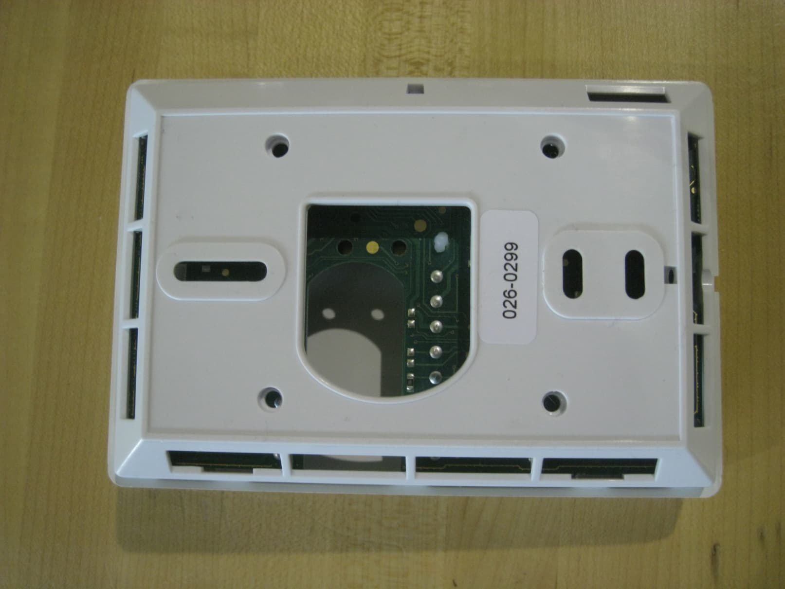
V95-VTR
Jun 27, 2010WIRELESS THERMOSTAT/DATA TERMINAL
Equipment Class
DTS - Digital Transmission System