V95-VWAPWireless door and window switch
Viconics Electronics Inc.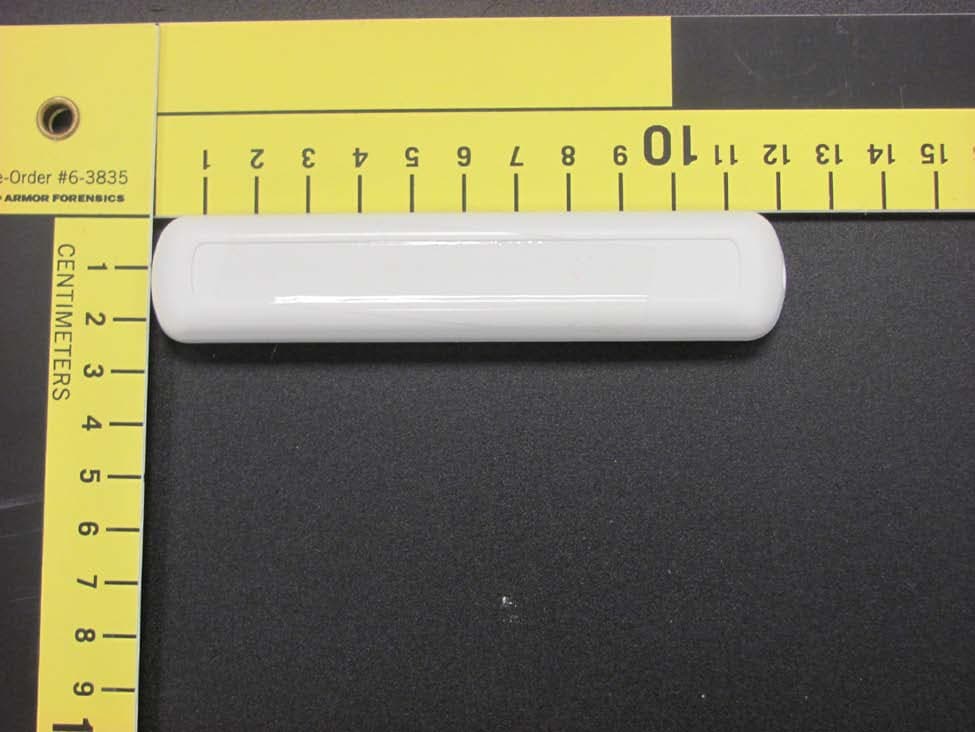
Click to zoom
Application Details
- Equipment Class
- DTS - Digital Transmission System
- Date of Grant
- Dec 18, 2013
- Application Purpose
- Original Equipment
- Date of Application
- Dec 18, 2013
- Equipment Note
- Wireless door and window switch
- Frequency Range
- 2405.00000000 - 2480.00000000
- Company
- Viconics Electronics Inc.
- Country
- Canada
Documents & Files
Document Text
Text extracted from the exhibit documents filed with the FCC. Open a document above to read the original.
Users Manual
1 Wireless Door/Window Switch SED - WIN/SED - DOR Wireless Door and Window Switch Installation Guide CONTENTS Installation 2 Self Testing 2 Location 2 Operation Overview 3 Model Chart 3 Pairing Process Procedure 4 Configuring Actions 4 Using SERx300 Controllers for Stand-alone Systems 4 Using SERx300 Controllers for Networked Systems 6 Important Notes Before Starting Pairing Procedure 7 Pairing – Associating Switches with Controllers 8 Multiple Switch Configuration 8 Troubleshooting Guide 9 Status and Monitoring 9 Battery Status 10 Specifications 10 Drawing and Dimensions 11 Marking Templates for Mounting 12 SED - WIN and SED - DOR 2 Wireless Door/Window Switch All brand names, trademarks and registered trademarks are the property of their respective owners. Information contained within this document is subject to change without notice. Schneider Electric One High Street, North Andover, MA 01845 USA Telephone: +1 978 975 9600 Fax: +1 978 975 9674 http://www.schneider-electric.com/buildings II-SE8000-SEDWINDOR-US.EN.10.2013.v1 October 2013 © 2013 Schneider Electric. All rights reserved. Figure-1 Open cover Figure-2 Install Switch and Magnet Bases INSTALLATION SED - WIN/SED - DOR Installation 1. Remove cover by pulling on side where security screw was mounted (Figure-1). 2. Remove cover of magnet unit. 3. Read FCC ID and IC label inside removed cover. 4. Cut out mounting template (end of this manual) for install. Do not place it on hinge side of door unless self tested. 5. Locate template and mark four holes for self-tapping screws. 6. Use self-tapping screws to install both switch and magnet base (Figure-2). 7. Follow pairing process before installing switch and magnet units. 8. After pairing process is successful, install switch and magnet units. 9. Install security screw on switch. Self Testing For best practice, the configuration of the wireless switch and magnet unit should be configured as shown. Use mounting template at the end of this document for installation. Other configurations can be used, such as placing devices on top of door, placed horizontally. Always self-test wireless switch to ensure it works correctly. Location • Never install switch unit on moving part (door or window). • Install only magnet unit on moving part (door or window). • Never install in direct sun. • Ensure minimum distance between any wireless node and any WiFi devices is at least 3 feet (1m). Notes • Electronic controls are static sensitive devices. Discharge yourself properly before manipulating and installing device. • A short circuit or wrong wiring may permanently equipment. • All SED-WIN and SED-DOR series controls are designed for use as operating controls only and are not safety devices. These instruments have undergone rigorous tests and verification prior to shipping to ensure proper and reliable operation in the field. Whenever a control failure could lead to personal injury and or loss of property, it becomes the responsibility of the user, installer, electrical system designer to incorporate safety devices (relays, flow switch, thermal protections), or an alarm system to protect the entire system against catastrophic failures. Tampering with devices or unintended application of devices results in void of warranty. • See data sheet for operating and storage conditions. • Any occurring condensation can damage wireless switch. • Respect polarity when replacing batteries. Reversing polarity of batteries can damage wireless switch. SED - WIN and SED - DOR 3 Wireless Door/Window Switch All brand names, trademarks and registered trademarks are the property of their respective owners. Information contained within this document is subject to change without notice. Schneider Electric One High Street, North Andover, MA 01845 USA Telephone: +1 978 975 9600 Fax: +1 978 975 9674 http://www.schneider-electric.com/buildings II-SE8000-SEDWINDOR-US.EN.10.2013.v1 October 2013 © 2013 Schneider Electric. All rights reserved. Operation Overview SED-WIN and SED-DOR series Zigbee Pro™ wireless switches are used with wireless versions of SERx3XX Series Fan Coil Terminal Equipment Controllers. A typical hospitality application SERx3xx wall terminal equipment controller has an on-board PIR sensor. Wireless switches monitor opening and closing of doors and windows. Wireless door switches used with local SERx3xx PIR cover provide advanced local occupancy routines allowing for increased energy savings during occupied hours without sacrificing occupant comfort. Wireless window switches monitor outside windows and/or opening/closing of patio/balcony doors, which prevents unnecessary energy consumption. Applications of SERx3xx Series Fan Coil Terminal Equipment Controllers with SED-WIN and SED-DOR series Zigbee Pro™ wireless switches can be used in network ready mode, with or without integration to a central management system. This allows for advanced functions such as central reser- vation occupancy functions. A combination of up to twenty SED-WIN and SED-DOR door and/or window switches can be used simultaneously with a single device. The SED-WIN and SED-DOR switches are factory delivered with 2 AAA batteries and can be installed, configured, and used right out of the box. Due to extremely small cur- rent consumption of the switches, the expected battery life is approximately 10 years. No tools are required for commissioning or servicing the door switch. A very simple interface with an on-board LED and hidden switch provides the required functions for local interaction. Local information for battery life and connectivity (heartbeat) are provided at the SERx3xx Series Fan Coil Terminal Equipment Controller local display level, or through the Zigbee Pro™ wireless network. Each switch is also factory supplied with a magnet, locking security tamper proof screw, and self tapping mounting screws for installation. Model Chart PART NUMBERDESCRIPTION SED-WIN-P-5000 Wireless Window Switch (Patio and balcony doors) Complete with magne…
Text truncated - open the document above for the full version.
Cover Letter(s)
Viconics Electronics Inc. Tel.: (514) 321-5660 9245 Langelier Blvd., St.Léonard, Québec Canada H1P 3K9 Fax: (514) 321-4150 www.viconics.com ISO 9001 & ISO 14001 CERTIFIED Federal Communications Commission Authorization and Evaluation Division Confidentiality Request regarding application for certification of FCC ID: V95-VWAP Pursuant to Sections 0.457 and 0.459 of the Commission’s Rules, we hereby request confidential treatment of information accompanying this application as outlined below: Exhibit Type File Name Schematics VWAP_Schem.pdf Parts List VWAP_ PartsLst.pdf Block diagrams VWAP_ BlkDia.pdf Operational Description VWAP_OpDes.pdf The above materials contain trade secrets and proprietary information not customarily released to the public. The public disclosure of these materials may be harmful to the applicant and provide unjustified benefits to its competitors. The applicant understands that pursuant to Section 0.457 of the Rules, disclosure of this application and all accompanying documentation will not be made before the date of the Grant for this application. Sincerely, Paolo Primiani
External Photos
Client Viconics Technologies Inc Product Wireless Door and Window Switch Standard(s) RSS 210 Issue 8:2010 / FCC Part 15 Subpart C 15:2013 Page 1 of 2 Report issue date: 12/6/2013 GEMC File #: GEMC-FCC-21447(SW)R1 Illustration 1: EUT front view Client Viconics Technologies Inc Product Wireless Door and Window Switch Standard(s) RSS 210 Issue 8:2010 / FCC Part 15 Subpart C 15:2013 Page 2 of 2 Report issue date: 12/6/2013 GEMC File #: GEMC-FCC-21447(SW)R1 Illustration 2: EUT rear view
Internal Photos
Client Viconics Technologies Inc Product Wireless Door and Window Switch Standard(s) RSS 210 Issue 8:2010 / FCC Part 15 Subpart C 15:2013 Page 1 of 2 Report issue date: 12/6/2013 GEMC File #: GEMC-FCC-21447(SW)R1 Figure 1: VWAP – front view Client Viconics Technologies Inc Product Wireless Door and Window Switch Standard(s) RSS 210 Issue 8:2010 / FCC Part 15 Subpart C 15:2013 Page 2 of 2 Report issue date: 12/6/2013 GEMC File #: GEMC-FCC-21447(SW)R1 Figure 2: VWAP – rear view
RF Exposure Info
Client Viconics Technologies Inc Product Wireless Door and Window Switch Standard(s) RSS 210 Issue 8:2010 / FCC Part 15 Subpart C 15:2013 Page 1 of 1 Report issue date: 12/6/2013 GEMC File #: GEMC-FCC-21447(SW)R1 Maximum Permissible Exposure Purpose The purpose of this test is to ensure that the RF energy intentionally transmitted, in terms of power density emitted from the EUT at a stated operating distance does not exceed the limits listed below as defined in the applicable test standard, as calculated based upon readings obtained during testing. This helps protect human exposure to excessive RF fields. Limit(s) and Method The limits, as defined in FCC 15.247(i) and FCC 1.1310 Table 1 (B) limits for general public exposure was applied. The limit for the frequency range of 1.5 GHz to 100 GHz was applied. This is a limit of 1.0 mW/ cm 2 . The distance used for calculations was 20cm, as this is the minimum distance an operator will be from the EUT during normal operation, as stated by the manufacturer. Results The EUT passed the requirements. The worst case calculated power density was 0.0004 mW/cm 2 , this is significantly under the 1.0 mW/cm 2 requirement. Calculations Method 1 (conducted power) Internal antenna P d = (P t *G) / (4*pi*R 2 ) Where Pt = 3.30 dBm or 2.14 mW as per Peak power conducted output Where G = 0 dBi, or numerically 1.0 Where R = 20 cm P d = (2.14 mW * 1.0) / (4 * pi * 20cm 2 ) P d = 2.14 mW / 5026 cm 2 P d = 0.0004 mW/cm 2
Test Report
LAB REGISTRATION #6844A-3 Testing Laboratory Certificate #2555.01 FCC REGISTRATION #377448 R-4023, G-506 T-1246, C-4498 Page 1 of 74 Report issue date: 12/6/2013 GEMC File #:GEMC-FCC-21447(SW)R1 © Glo bal EMC Inc. This test report shall not be reproduced except in full, without written approval of Global EMC Inc. This report is based on GEMC Template “FCC 15 247 Rev2.” Global EMC Inc. Labs EMC & RF Test Report As per RSS 210 Issue 8:2010 & FCC Part 15 Subpart C:2013 Unlicensed Intentional Radiators on the Wireless Door and Window Switch Min Xie Project Engineer 11 Gordon Collins Dr, Gormley, ON, L0H 1G0 Canada Ph: (905) 883-8189 Testing produced for See Appendix A for full customer & EUT details. Client Viconics Technologies Inc Product Wireless Door and Window Switch Standard(s) RSS 210 Issue 8:2010 / FCC Part 15 Subpart C 15:2013 Page 2 of 74 Report issue date: 12/6/2013 GEMC File #: GEMC-FCC-21447(SW)R1 © Glo bal EMC Inc. This test report shall not be reproduced except in full, without written approval of Global EMC Inc. Table of Contents Table of Contents ................................................................................................................... 2 Report Scope .......................................................................................................................... 3 Summary ................................................................................................................................ 4 Test Results Summary ....................................................................................................... 5 Justifications, Descriptions, or Deviations......................................................................... 6 Applicable Standards, Specifications and Methods ........................................................... 7 Sample calculation(s) ......................................................................................................... 8 Document Revision Status ................................................................................................. 8 Definitions and Acronyms ..................................................................................................... 9 Testing Facility .................................................................................................................... 10 Calibrations and Accreditations ....................................................................................... 10 Testing Environmental Conditions and Dates ................................................................. 11 Detailed Test Results Section .............................................................................................. 12 6dB Bandwidth of Digitally Modulated Systems ............................................................ 13 Antenna Spurious Conducted Emissions (-20 dBc Requirement) ................................... 21 Transmitter Spurious Radiated Emissions ....................................................................... 30 Power Spectral Density - DM .......................................................................................... 57 Maximum Permissible Exposure ..................................................................................... 62 Appendix A – EUT Summary .............................................................................................. 64 Appendix B – EUT and Test Setup Photographs................................................................. 65 Client Viconics Technologies Inc Product Wireless Door and Window Switch Standard(s) RSS 210 Issue 8:2010 / FCC Part 15 Subpart C 15:2013 Page 3 of 74 Report issue date: 12/6/2013 GEMC File #: GEMC-FCC-21447(SW)R1 © Glo bal EMC Inc. This test report shall not be reproduced except in full, without written approval of Global EMC Inc. Report Scope This report addresses the EMC verification testing and test results of Viconics Technologies Inc’s Wireless Door and Window Switch, herein referred to as EUT (Equipment Under Test) performed at Global EMC Labs. The EUT was tested for compliance against the following standards: RSS 210 Issue 8:2010 FCC Part 15 Subpart C 15:2013 Test procedures, results, justifications, and engineering considerations, if any, follow later in this report. The results contained in this report relate only to the item(s) tested. This report does not imply product endorsement by A2LA or any other accreditation agency, any government, or Global EMC Inc. Opinions/interpretations expressed in this report, if any, are outside the scope of Global EMC Inc accreditation. Any opinions expressed do not necessarily reflect the opinions of Global EMC Inc, unless otherwise stated. Client Viconics Technologies Inc Product Wireless Door and Window Switch Standard(s) RSS 210 Issue 8:2010 / FCC Part 15 Subpart C 15:2013 Page 4 of 74 Report issue date: 12/6/2013 GEMC File #: GEMC-FCC-21447(SW)R1 © Glo bal EMC Inc. This test report shall not be reproduced except in full, without written approval of Global EMC Inc. Summary The results contained in this report relate only to the item(s) tested. EUT FCC Certification #, FCC ID: V95-VWAP EUT Industry Canada Certification #, IC: 7591A-VWAP EUT Passed all tests performed. Yes (see test results summary) Tests conducted by Min Xie Client Viconics Technologies Inc Product Wireless Door and Window Switch Standard(s) RSS 210 Issue 8:2010 / FCC Part 15 Subpart C 15:2013 Page 5 of 74 Report issue date: 12/6/2013 GEMC File #: GEMC-FCC-21447(SW)R1 © Glo bal EMC Inc. This test report shall not be reproduced except in full, without written approval of Global EMC Inc. Test Results Summary Standard/Method Description Class/Limit Result FCC 15.203 Antenna Requirement Unique Pass See Justification FCC 15.205 RSS 210 (Table 1) Restricted Bands for intentional operation QuasiPeak Average Pass FCC 15.207 Power line conducted emissions QuasiPeak Average N/A See Justifications FCC 15.209 RSS-210 (Table 2) Spurious Radiated …
Text truncated - open the document above for the full version.
Test Setup Photos
Client Viconics Technologies Inc Product VWAP Door and Window Switch Standard(s) RSS 210 Issue 8:2010 / FCC Part 15 Subpart C 15:2013 Page 1 of 4 Report issue date: 12/6/2013 GEMC File #: GEMC-FCC-21447(SW)R1 Illustration 1: Radiated emission setup – photo 1 Client Viconics Technologies Inc Product VWAP Door and Window Switch Standard(s) RSS 210 Issue 8:2010 / FCC Part 15 Subpart C 15:2013 Page 2 of 4 Report issue date: 12/6/2013 GEMC File #: GEMC-FCC-21447(SW)R1 Illustration 2: Radiated emission setup - photo 2 Client Viconics Technologies Inc Product VWAP Door and Window Switch Standard(s) RSS 210 Issue 8:2010 / FCC Part 15 Subpart C 15:2013 Page 3 of 4 Report issue date: 12/6/2013 GEMC File #: GEMC-FCC-21447(SW)R1 Illustration 3: Radiated setup - photo 3 Client Viconics Technologies Inc Product VWAP Door and Window Switch Standard(s) RSS 210 Issue 8:2010 / FCC Part 15 Subpart C 15:2013 Page 4 of 4 Report issue date: 12/6/2013 GEMC File #: GEMC-FCC-21447(SW)R1 Illustration 4: Antenna conducted emission setup
Contact Information
Applicant
Emmanuel Stathopoulos(Certification)
Test Firm
TUV SUD CANADA (Gormley)William (Mac) Elliott
[email protected]813-284-2736
Technical Specifications
| # | Rule Parts | Frequency Range | Power Output |
|---|---|---|---|
| 1 | 15C | 2.40 GHz - 2.48 GHz | 2.00 mW |
Other Applications from Viconics Electronics Inc.
V95-WIS
Aug 17, 2015Thermostat
Equipment Class
DTS - Digital Transmission System
V95-VTP
Dec 13, 2012WIRELESS THERMOSTAT DATA TERMINAL
Equipment Class
DTS - Digital Transmission System
V95-VWA
May 11, 2011WIRELESS SWITCH ACCESSORY FOR THERMOSTAT APPLICATIONS
Equipment Class
DTS - Digital Transmission System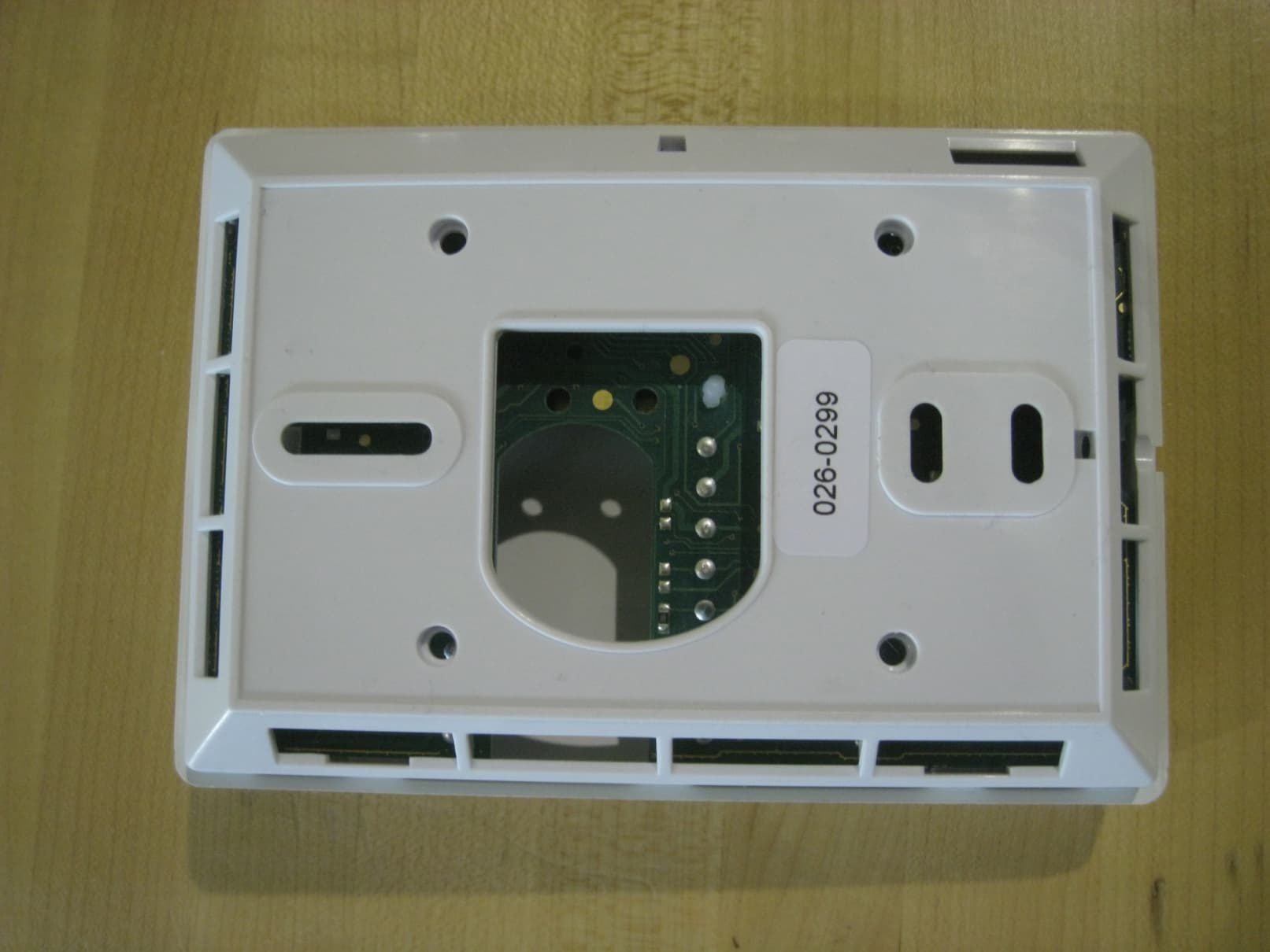
V95-VTR
Jun 27, 2010WIRELESS THERMOSTAT/DATA TERMINAL
Equipment Class
DTS - Digital Transmission System