VA8LB010Communications Receiver
Wolf Steel Ltd.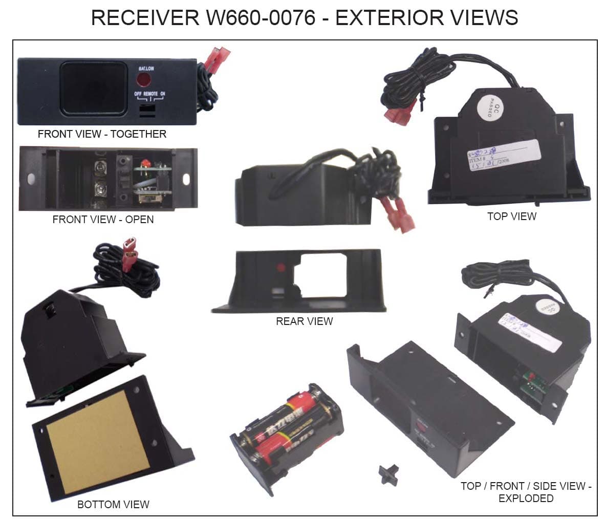
Click to zoom
Application Details
- Equipment Class
- CYY - Communications Receiver used w/Pt 15 Transmitter
- Date of Grant
- Mar 04, 2008
- Application Purpose
- Original Equipment
- Date of Application
- Mar 03, 2008
- Equipment Note
- Communications Receiver
- Frequency Range
- 303.80000000 - 303.80000000
- Company
- Wolf Steel Ltd.
- Country
- Canada
Documents & Files
Document Text
Text extracted from the exhibit documents filed with the FCC. Open a document above to read the original.
Users Manual
The F-40 and the F-50 transmitter units have been approved for use with most Wolf Steel gas fi replaces using a millivolt system. The Receiver (W660-0076) can be installed in either the fi replace or be wall mounted depending on the application. The F-40 provides on/off status, and the current room temperature as well as having a low battery indicator. It allows you to switch the fi replace on or off from anywhere in the room. The F-50 is a thermostatically controlled transmitter that provides on/off status, displays room/set temperature as well as having a low battery indicator. These transmitter kits are tested and safe when installed in accordance with these instructions. Modifi cation of any part of this kit will void any warranty claims and could create a fi re hazard. RECEIVER INSTALLATION: Turn off the electrical power and the gas supply to the fi replace. (Gas supply may need to be disconnected from the gas control valve.) Make sure the slide switch on the receiver is set to the OFF position. 1. Either disconnect or connect in parallel* with any other transmitter wiring from the valve. Attach the wires from terminal 1 (TPTH) and terminal 3 (TH) of the gas valve to the output terminals on the receiver. *INSTALLER: It may be advisable to connect a switch with short lengths of wire to minimize the resistance. This will allow the homeowner to continue to control the burner in the event of battery failure. For all millivolt switch wiring, hook up the switch leads on terminals 1 and 3 of the gas valve. WALL MOUNT: 2. Press the battery compartment slightly into the receiver and release enabling the battery compartment to pop out. Pull off the slide switch. Slide the receiver out of the fi replace mounting plate. 3. Using the screws provided secure the receiver and the face plate to an existing junction box. 4. Replace the slide switch. Place 4 AA batteries into the battery compartment and slide the compartment back into the receiver. 5. If the gas supply was disconnected at the valve, leak test using a soap and water solution. Turn electricity back on. FIREPLACE MOUNT: For stove and insert models: do not install the receiver in the gas control valve compartment as this area becomes too hot. On stoves, it may be installed in or behind the pedestal; on inserts, it may be installed behind the fl ashings or a similar convenient location. In a zero clearance model: the receiver may be installed in the gas control compartment. 2. Ensuring that the mounting location will allow for the battery compartment to slide out, secure the receiver to an appropriate location depending on the fi replace model using the screws provided and/or the adhesive pad. 3. If the gas supply was disconnected at the valve, leak test using a soap and water solution. Turn electricity back on. W415-0628 / 11.20.07 FIREPL ACE REM OT E OFF O N RE M OT E BA T.LOW JUNCTION BOX RECEIVER SLIDE SWITCH FACEPLATE WALL MOUNT EXPLODED VIEW FIR EPLA C E R EM O TE PRE SS T O OPE N OF F ON R E M O T E BA T . L O W BATTERY COMPARTMENT WALL MOUNT UN-EXPLODED VIEW B A T. LO W OFF REMO TE O N FIREPLACE MOUNTING PLATE FIREPLACE MOUNT EXPLODED VIEW RECEIVER SLIDE SWITCH FIREPLACE MOUNT UN-EXPLODED VIEW B A T .LO W O FF REMO TE O N PRE SS T O OPEN BATTERY COMPARTMENT F-40 AND F-50 TRANSMITTER UNIT INSTALLATION AND OPERATION INSTRUCTIONS F-40 Includes: F-50 Includes: W660-0066 Transmitter W660-0067 Transmitter W660-0076 Receiver W660-0076 Receiver TRANSMITTER WALL MOUNT: Secure to the desired wall location using screws, and anchors if required. RECEIVER OPERATION: The receiver switch must be in the TRANSMITTER position for the transmitter to function. F-50 THERMOSTATIC FUNCTION: Thermostatic control automatically cycles the fi replace on and off to maintain the desired room temperature. To turn the fi replace burner on, press the (ON/OFF) button. The LCD will display the word “ON” and the fl ame indicator will be shaded in. The (ON/OFF) button is used to turn the fi replace on or off only. It does not set temperature. The (THERMOSTAT) button is used to control room temperature. Once pushed, “ON” lights up next to the thermostat bulb located in the top left corner of the LCD screen. Set desired room temperature using the (UP) and (DOWN) buttons. If the temperature of the room exceeds the desired room temperature, the thermostat will automatically turn the fi replace “OFF”. CAUTION: In the event that the transmitter fails to send a signal to the receiver for a period of twenty-four hours, the receiver will automatically turn OFF the fi replace. This may occur if the set temperature is not reached, if the transmitter is out of range (25 feet), or if the transmitter batteries fail. The twenty-four hour safety timer allows the receiver to assume control of the fi replace after two hours of uninterrupted operation. After two hours of continuous operation by the fi replace the receiver will cycle OFF for 30 minutes and ON for 20 minutes for the next four hours. If a signal has not been received after twenty-four hours the receiver will shut OFF the fi replace. Press the AUTO ON/OFF button on the transmitter to reset the transmitter, then press the AUTO ON/OFF button again to resume operation. The six hour safety timer may be disengaged by moving the toggle switch on the back of the receiver. Factory setting is ON. Changing the switch will allow the fi replace to run continuously if required. WARNING: In the event of prolonged absences, the F-50 should not be left in thermostat mode. If the transmitter batteries fail while the fi replace is operating the receiver will assume control and shut OFF the fi replace after twenty-four hours. If the transmitter batteries fail while the fi replace is not operating the fi replace will remain OFF. TEMPERATURE FUNCTION: Remove the battery cover on the back of the transmitter to expose the °C/°F dip switch. Move the dip switch to your desired temperature mode. Selected mode will appear in the right corner beside …
Text truncated - open the document above for the full version.
Cover Letter(s)
Receiver - W660-0076 VA8LB010
ID Label/Location Info
LABEL FORMAT This device copmplies with Part 15 of the FCC Rules. Operation is subject to the following two conditions: (1) This device may not cause harmful interference, and (2) This device must accept any interference received, including interference that may cause undesired operation. Made in PRC MODELNo.: W660-0076 IC: 7114A-LB010 FCC ID: VA8LB010 52 mm 26 mm W660-0076 LABEL INFORMATION LABEL LOCATION BOTTOM VIEW This device copmplies with Part 15 of the FCC Rules. Operation is subject to the following two conditions: (1) This device may not cause harmful interference, and (2) This device must accept any interference received, including interference that may cause undesired operation. Made in PRC MODELNo.: W660-0076 IC: 7114A-LB010 FCC ID: VA8LB010 52 mm 26 mm LABEL LOCATION 24 mm 10 mm 7.5 mm 7.5 mm
Internal Photos
RECEIVER W660-0076 - EXTERIOR VIEWS RECEIVER W660-0076 - BOARD VIEWS TOP BOARD, TOP VIEW TOP BOARD, BOTTOM VIEW BOTTOM BOARD, TOP VIEW BOTTOM BOARD, BOTTOM VIEW FRONT VIEW - TOGETHERFRONT VIEW - TOGETHER FRONT VIEW - OPEN TOP VIEW REAR VIEW BOTTOM VIEW TOP / FRONT / SIDE VIEW - EXPLODED
Parts List/Tune Up Info
Receiver (W660-0076) Part List Used Part Type Designator Description 1 4pF C1 Chip Capacitor ±0.1pF NPO, High Q , Low ESR 4 15pF C2 C3 C5 C9 Chip Capacitor ±0.1pF NPO, High Q ,Low ESR 1 30pF C10 Chip Capacitor ±10% X7R, 50V 1 220pF C6 Chip Capacitor ±10% X7R, 50V 1 1nF C4 Chip Capacitor ±10% X7R, 50V 1 10nF C15 Chip Capacitor ±10% X7R, 50V 2 100nF C13 C14 Chip Capacitor ±10% X7R, 50V 7 0.1uF C12 C16 C17 C18 C19 C20 C21 Chip Capacitor ±10% X7R, 50V 2 0.47uF C7 C8 Chip Capacitor ±10% X7R, 50V 1 10uF C11 Chip Capacitor ±10% X7R, 50V 1 20uF C22 Chip Capacitor ±10% X7R, 50V 1 33uF E1 Chip Capacitor ±20% Tantal , 6V 1 50 R7 Chip Resistor ± 10% 1/8W 1 100 R12 Chip Resistor ± 10% 1/8W 3 1K R13 R17 R18 Chip Resistor ±10% 1/8W 3 4.7K R2 R15 R16 Chip Resistor ± 10% 1/8W 1 10K R11 Chip Resistor ± 10% 1/8W 1 39K R14 Chip Resistor ± 10% 1/8W 1 47K R1 Chip Resistor ±10% 1/8W 1 100K R8 Chip Resistor ±10% 1/8W 1 330K R10 Chip Resistor ± 10% 1/8W Page 1 of 2 1 2M R6 Chip Resistor ± 10% 1/8W 1 4.7M R5 Chip Resistor ± 10% 1/8W 3 10M R3 R4 R9 Chip Resistor ± 10% 1/8W 1 10nH L1 Coil Inductor 1 76.8K Y1 Crystal 100ppm Load 10pF, ESR <100 1 93C46 U6 EEPRAM 1 4069 U1 Hex Inverter 1 4148 D1 Diode 1 9014 Q2 NPN Transistor 1 BUZZER U4 Buzzer 1 2SC3356 T1 NPN Transistor 1 CON2 J3 1 EM78P156 U2 MCU 1 HT7133-1 U5 3.3V Regulator 1 LED LED1 LED 1 SDM6912 U3 N Channel Power FET 1 SW-PB S1 Push Key 1 SW DPDT3 K1 Three Position Slid Switch Page 2 of 2
Test Report
www.nemko.com FCC Part 15 Subpart B, October 2006 Test Report: 80288-2R1TRFWL Applicant: WOLF STEEL LTD 9 NAPOLEON RD, BARRIE, ONTARIO L4M 4Y8 Apparatus: 303.8 MHz Remote Controller System – Receiver, Model: W660-0076 FCC ID: VA8LB010 In Accordance With: FCC Part 15 Subpart B, 15.107 and 15.109 Unintentional Radiators Tested By: Nemko Canada Inc. 303 River Road Ottawa, Ontario K1V 1H2 Authorized By: Jason Nixon, Wireless Specialist Date: February 25, 2008 Total Number of Pages: 12 Nemko Canada Inc. REPORT SUMMARY Report Number: 80288-2R1TRFWL FCC ID: VA8LB010 Specification: FCC Part 15 Subpart B Page 2 of 12 Report Summary These tests were conducted on a sample of the equipment for the purpose of demonstrating compliance with Part 15, Subpart B. Radiated tests were conducted in accordance with ANSI C63.4-2003. Radiated emissions are made on an open area test site. A description of the test facility is on file with the FCC. The assessment summary is as follows: Apparatus Assessed: 303.8 MHz Remote Controller System – Receiver, Model: W660-0076 Specification: FCC Part 15 Subpart B, 15.107 and 15.109 Compliance Status: Complies Exclusions: None Non-compliances: None Report Release History: Release 1 Radiated emission was re-assessed with the final enclosure. Author: Heng Lin, EMC/Wireless Specialist Note that the results contained in this report relate only to the items tested and were obtained in the period between the date of initial receipt of samples and the date of issue of the report. This test report has been completed in accordance with the requirements of ISO/IEC 17025. Nemko Canada Inc. authorizes the applicant to reproduce this report provided it is reproduced in its entirety and for use by the company’s employees only. Any use which a third party makes of this report, or any reliance on or decisions to be made based on it, are the responsibility of such third parties. Nemko Canada Inc. accepts no responsibility for damages, if any, suffered by any third party as a result of decisions made or actions based on this report. Nemko Canada Inc. REPORT SUMMARY Report Number: 80288-2R1TRFWL FCC ID: VA8LB010 Specification: FCC Part 15 Subpart B Page 3 of 12 TABLE OF CONTENTS Report Summary......................................................................................................................................... 2 Section 1 : Equipment Under Test............................................................................................................. 4 1.1 Product Identification .................................................................................................................................4 1.2 Samples Submitted for Assessment............................................................................................................4 1.3 Theory of Operation ...................................................................................................................................4 1.4 Technical Specifications of the EUT ..........................................................................................................5 1.5 Block Diagram of the EUT.........................................................................................................................5 Section 2 : Test Conditions......................................................................................................................... 6 2.1 Specifications .............................................................................................................................................6 2.2 Deviations From Laboratory Test Procedures ............................................................................................6 2.3 Test Environment .......................................................................................................................................6 2.4 Test Equipment...........................................................................................................................................6 2.5 Measurement Uncertainty...........................................................................................................................6 Section 3 : Observations ............................................................................................................................. 7 3.1 Modifications Performed During Assessment ............................................................................................7 3.2 Record Of Technical Judgements ...............................................................................................................7 3.3 EUT Parameters Affecting Compliance .....................................................................................................7 3.4 Test Deleted................................................................................................................................................7 3.5 Additional Observations .............................................................................................................................7 Section 4 : Results Summary ..................................................................................................................... 8 4.1 FCC Part 15 Subpart C : Test Results ........................................................................................................9 Appendix A : Test Results ........................................................................................................................ 10 Clause 15.109(a) Radiated Emissions (unintentional radiator, Class B) .............................................................10 Appendix B : Setup Photographs ............................................................................................................ 11 Appendix C : Block Diagram of Test Setups .......................................................................................... 12 Nemko Canada Inc. SECTION 1 : EQUIPMENT UNDER …
Text truncated - open the document above for the full version.
Test Setup Photos
Nemko Canada Inc. APPENDIX B : SETUP PHOTOGRAPHS Report Number: 80288-2R1TRFWL FCC ID: VA8LB010 Specification: FCC Part 15 Subpart B Page 11 of 11 Appendix B : Setup Photographs Radiated Emissions Setup (Receiver):
Contact Information
Applicant
Paul Hodges(Innovation and Engineering Systems Manager)
Technical Contact
Yuanben Technology Development Co. Ltd.Dongming Zhou
[email protected](86-731) 419-7488
Room 1421, Huahai 3C Plaza, East Jiefang Road · Changsha City · China
Non-Technical Contact
Wolf Steel Ltd.Todd Bush
[email protected]705-721-1212
Test Firm
Nemko Canada IncStuart Beck
Technical Specifications
| # | Rule Parts | Frequency Range | Power Output |
|---|---|---|---|
| 1 | 15B | 303.8 MHz - 303.8 MHz | - |
Other Applications from Wolf Steel Ltd.
VA8-PRO665VX
Feb 05, 2026Napoleon Prestige Pro
Equipment Class
DTS - Digital Transmission SystemVA8-P665VXRSIBPSS
Apr 14, 2024Prestige
Equipment Class
DSS - Part 15 Spread Spectrum Transmitter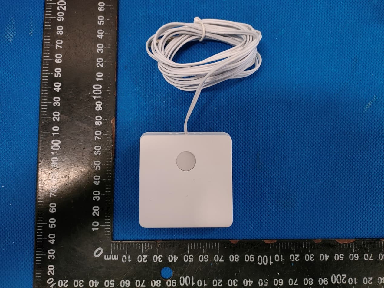
VA8-WSC-IS
Jun 19, 2022Temperature Sensor
Equipment Class
DXX - Part 15 Low Power Communication Device Transmitter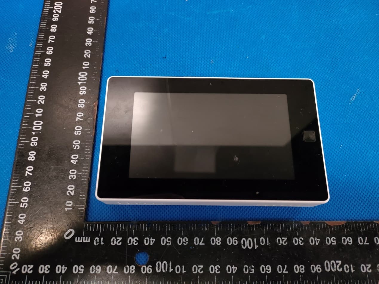
VA8-WSC43BA
Jun 18, 2022WiFi Thermostat
Equipment Class
DSS - Part 15 Spread Spectrum Transmitter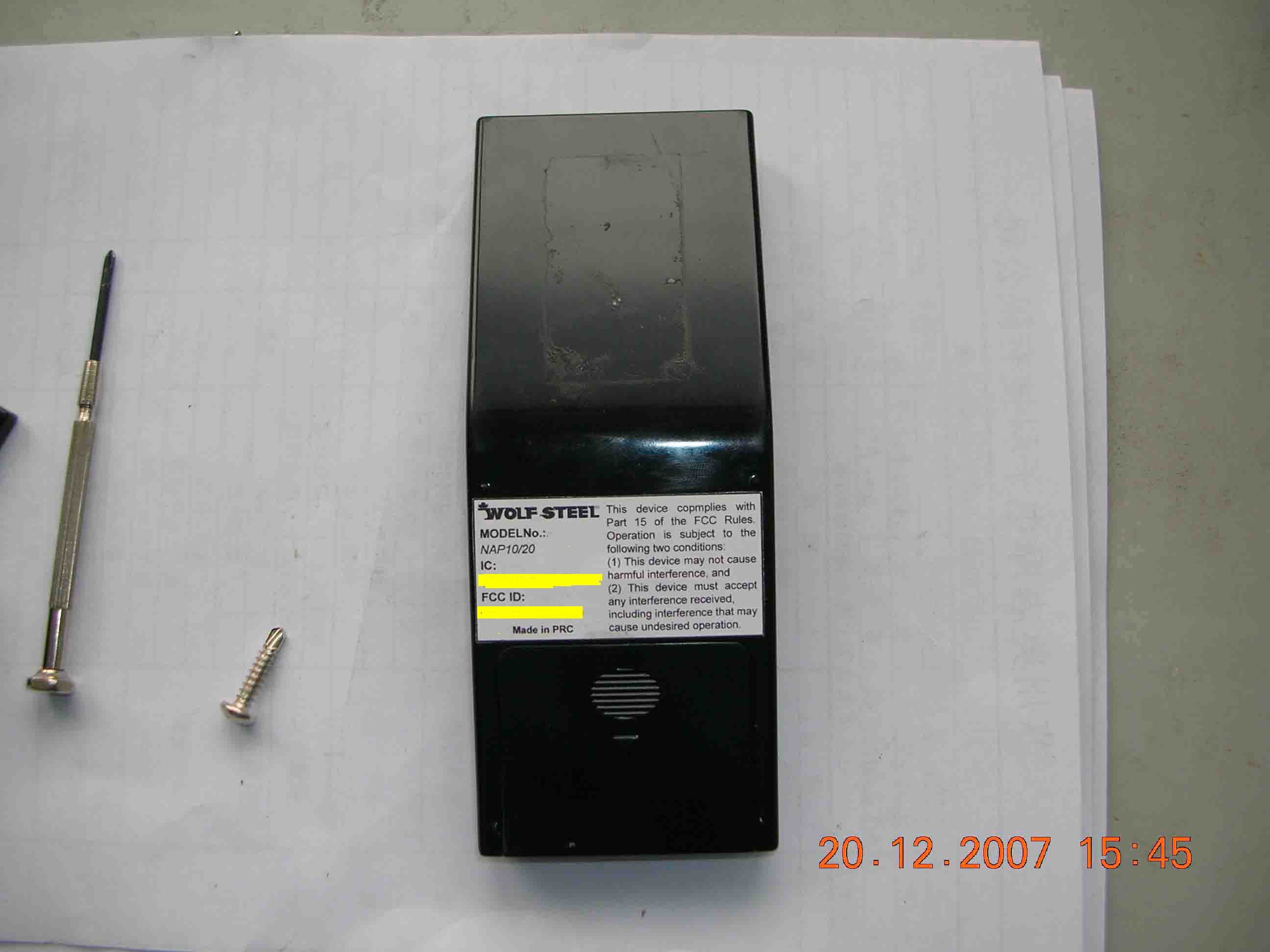
VA8LB020
Mar 04, 2008Remote Control Transmitter
Equipment Class
DSC - Part 15 Security/Remote Control Transmitter