VDE-0G6019BGenerator Transceiver
Generac Power Systems Inc.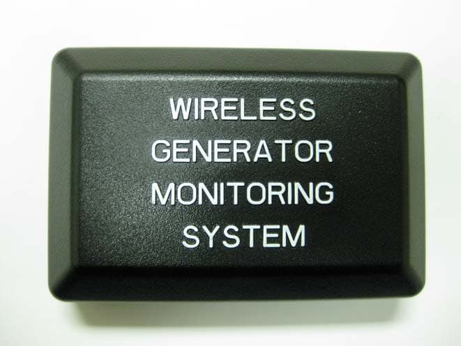
Click to zoom
Application Details
- Equipment Class
- DTS - Digital Transmission System
- Date of Grant
- Feb 01, 2010
- Application Purpose
- Original Equipment
- Date of Application
- Feb 01, 2010
- Equipment Note
- Generator Transceiver
- Frequency Range
- 2405.00000000 - 2440.00000000
- Company
- Generac Power Systems Inc.
- Country
- United States
Documents & Files
Document Text
Text extracted from the exhibit documents filed with the FCC. Open a document above to read the original.
Users Manual
Wireless Display System Instruction Manual Proof #1 01/15/09 TABLE OF CONTENTS SAFETY ........................................................... Inside Front Cover Read This Manual Thoroughly ........................................... 1 Safety Rules ..................................................................... 1 Operation and Maintenance ............................................... 3 How to Obtain Service ...................................................... 3 INTRODUCTION ........................................................................ 3 BATTERY OPERATION ............................................................... 3 INSTALLATION .......................................................................... 4 Generator Side Transceiver Installation Instructions ........... 4 Display Installation ............................................................ 5 THE COMMUNICATIONS LED .................................................... 6 GENERATOR COMMUNICATIONS .............................................. 6 THE DISPLAY ............................................................................ 6 Contrast Adjustment ......................................................... 6 Backlight .......................................................................... 6 Buttons ............................................................................. 7 Battery and Signal Strength Indicators ............................... 7 ALARM AND STATUS DISPLAY ................................................. 7 THE MENU SYSTEM ................................................................. 7 Status Menu ..................................................................... 8 Test Menu ......................................................................... 8 History Menu .................................................................... 8 SETTINGS MENU ...................................................................... 9 Adjust Contrast ................................................................. 9 EXERCISE MENU ...................................................................... 9 RADIO MENU ............................................................................ 9 Radio Information ............................................................. 9 Changing Channels ........................................................... 9 Reset Radio ...................................................................... 9 Add New Display ............................................................ 10 Test Radio Link ............................................................... 10 TIME & DATE MENU ............................................................... 10 GRAPH MENU ......................................................................... 10 MENU MAP ............................................................................. 11 FADD ASSEMBLY .................................................................... 12 NOTES .................................................................................... 13 WARRANTY ...............................................................Back Cover SAFETY Compliance Statement (Part 15.19) This device complies with Part 15 of the FCC Rules. Operation is subject to the following two conditions: 1. This device may not cause harmful interference, and 2. This device must accept any interference received, including interference that may cause undesired operation. Warning (Part 15.21) Changes or modifications not expressly approved by the party responsible for compliance could void the user's authority to operate the equipment. FCC Interference Statement (Part 15.105 (b)) This equipment has been tested and found to comply with the limits for a Class B digital device, pursuant to Part 15 of the FCC Rules. These limits are designed to provide reasonable protection against harmful interference in a residential instal- lation. This equipment generates uses and can radiate radio frequency energy and, if not installed and used in accordance with the instructions, may cause harmful interference to radio communications. However, there is no guarantee that interfer- ence will not occur in a particular installation. If this equipment does cause harmful interference to radio or television reception, which can be determined by turning the equipment off and on, the user in encouraged to try to correct the interference by one of the following measures: Reorient or relocate the receiving antenna.• Increase the separation between the equipment and receiver.• Connect the equipment into an outlet on a circuit different from • that to which the receiver is connected. Consult the dealer or an experienced radio/TV technician for • help. To comply with FCC/IC RF exposure limits for general population / uncontrolled exposure, the antenna(s) used for this transmitter must be installed to provide a separation distance of at least 20 cm from all persons and must not be co-located or operating in conjunction with any other antenna or transmitter. RF Exposure (OET Bulletin 65) To comply with FCC/IC RF exposure requirements for mobile transmitting devices, this transmitter should only be used or installed at locations where there is at least 20 cm separation distance between the antenna and all persons. Section 7.1.5 of RSS-GEN Operation is subject to the following two conditions: 1. This device may not cause interference, and 2. This device must accept any interference, including interfer- ence that may cause undesired operation of the device. Table of Contents 1 Important Safety Instructions READ THIS MANUAL THOROUGHLY If any portion of this manual is not understood, contact the near- est Authorized Service Dealer for starting, operating and servicing procedures. Throughout this publication, and on tags and decals affixed to the generator, DANGER, WARNING, CAUTION and NOTE blocks are used to alert personnel to special instructions about a particular service or ope…
Text truncated - open the document above for the full version.
External Photos
EXTERNAL PHOTOS COMPANY NAME: Generac Power Systems PRODUCT NAME: End Station MODEL NUMBER(S): 0G6019B FCC ID #: VDE-0G6019B IC #: 8036A-0G6019B PHOTO # 1 of 3 EXTERNAL PHOTOS Page 1 of 3 Top of Unit Side #1 EXTERNAL PHOTOS COMPANY NAME: Generac Power Systems PRODUCT NAME: End Station MODEL NUMBER(S): 0G6019B FCC ID #: VDE-0G6019B IC #: 8036A-0G6019B PHOTO # 2 of 3 EXTERNAL PHOTOS Page 2 of 3 Side #2 Side #3 EXTERNAL PHOTOS COMPANY NAME: Generac Power Systems PRODUCT NAME: End Station MODEL NUMBER(S): 0G6019B FCC ID #: VDE-0G6019B IC #: 8036A-0G6019B PHOTO # 3 of 3 EXTERNAL PHOTOS Page 3 of 3 Side #4 NOTE: There is no bottom cover for the “Annunciator”. It mounts on the side of the generator enclosure and uses a gasket, set into the end station case, to keep out moisture. So the photograph of the “Annunciator” looking into the case, showing the component side of the PCB, is the bottom view.
Internal Photos
INTERNAL PHOTOS COMPANY NAME: Generac Power Systems PRODUCT NAME: End Station MODEL NUMBER(S): 0G6019B FCC ID #: VDE-0G6019B IC #: 8036A-0G6019B PHOTO # 1 of 4 INTERNAL PHOTOS Page 1 of 4 Open for Inspection Close-Up of Board, View #1 INTERNAL PHOTOS COMPANY NAME: Generac Power Systems PRODUCT NAME: End Station MODEL NUMBER(S): 0G6019B FCC ID #: VDE-0G6019B IC #: 8036A-0G6019B PHOTO # 2 of 4 INTERNAL PHOTOS Page 2 of 4 Close-Up of Board, View #2 Close-Up of Board, View #3 INTERNAL PHOTOS COMPANY NAME: Generac Power Systems PRODUCT NAME: End Station MODEL NUMBER(S): 0G6019B FCC ID #: VDE-0G6019B IC #: 8036A-0G6019B PHOTO # 3 of 4 INTERNAL PHOTOS Page 3 of 4 Close-Up INTERNAL PHOTOS COMPANY NAME: Generac Power Systems PRODUCT NAME: End Station MODEL NUMBER(S): 0G6019B FCC ID #: VDE-0G6019B IC #: 8036A-0G6019B PHOTO # 4 of 4 INTERNAL PHOTOS Page 4 of 4 Back Side of Board, View #1 Back Side of Board, View #2
RF Exposure Info
EXHIBIT 12. MPE CALCULATIONS The following MPE calculations are based on a 1.8 centimeter inverted-F printed circuit board trace antenna, with a measured ERP of 110 dBμV/m, at 3 meters, and conducted RF power of +15.32 dBm as presented to the antenna. The calculated gain of this antenna, based on the ERP measurements is 0.25 dBi.
Test Report
W66 N220 Commerce Court ● Cedarburg, WI 53012 ● USA Phone: 262.375.4400 ● Fax: 262.375.4248 www.lsr.com Compliance Testing of: Generac® End Station Model VDE 0G6019B Test Date(s): October 25 th , 2008 & September 22 nd – 25 th , 2009 Prepared For: Generac Power Systems Attn: Steve Wilcox Hwy. 59 & Hillside Road P.O. Box 8 Waukesha 53187 Test Report Number: 309366 Project Number: C-758 In accordance with: Federal Communications Commission (FCC) Part 15, Subpart C, Section 15.247 Digital Modulation Transmitters (DTS) Operating in the Frequency Band 2400 MHz – 2483.5 MHz Test Project Engineer: Ryan M. Urness, EMC Laboratory Manager Signature: Date: February 1, 2010 Quality Assurance: Teresa A. White, Quality Manager Signature: Date: February 1, 2010 Reviewed by: Khairul Aidi Zainal, Sr. EMC Engineer Signature: Date: February 1, 2010 This Test Report may not be reproduced, except in full, without written approval of LS Research, LLC. Prepared For: Generac Power Systems Model #: 0G6019B LS Research, LLC EUT: End Station IC: 8036B-0G6019B Template: 15.247 DTS TX (V2 9-06-06) Report #: 309366 FCC ID #: VDE-0G6019B Page 2 of 48 TABLE OF CONTENTS (page 1 of 2) EXHIBIT 1. INTRODUCTION 4 1.1 Scope 4 1.2 Normative References 4 1.3 LS Research, LLC Test Facility 5 1.4 Location of Testing 5 1.5 Test Equipment Utilized 5 EXHIBIT 2. PERFORMANCE ASSESSMENT 6 2.1 Client Information 6 2.2 Equipment Under Test (EUT) Information 6 2.3 Associated Antenna Description 6 2.4 EUT’s Technical Specifications 7 2.5 Product Photo 8 EXHIBIT 3. EUT OPERATING CONDITIONS & CONFIGURATIONS DURING TESTS 9 3.1 Climate Test Conditions 9 3.2 Applicability & Summary of EMC Emission Test Results 9 3.3 Modifications Incorporated in the EUT for Compliance Purposes 9 3.4 Deviations & Exclusions from Test Specifications 9 EXHIBIT 4. DECLARATION OF CONFORMITY 10 EXHIBIT 5. RADIATED EMISSIONS TEST 11 5.1 Test Setup 11 5.2 Test Procedure 11 5.3 Test Equipment Utilized 11 5.4 Test Results 12 5.5 Calculation of Radiated Emission Measurements 12 5.6 Radiated Emissions Test Data Chart 13-14 5.7 Test Setup Photo(s)-Radiated Emissions Test 15 5.8 Screen Captures-Radiated Emissions Testing 16-24 EXHIBIT 6. CONDUCTED EMISSIONS TEST, AC POWER LINE: 15.207 25 6.1 Test Results 25 EXHIBIT 7. OCCUPIED BANDWIDTH; 15.247(a)(2) 26 7.1 Limits 26 7.2 Method of Measurements 26 7.3 Test Equipment List 26 7.4 Screen Captures – Occupied Bandwidth 27 Prepared For: Generac Power Systems Model #: 0G6019B LS Research, LLC EUT: End Station IC: 8036B-0G6019B Template: 15.247 DTS TX (V2 9-06-06) Report #: 309366 FCC ID #: VDE-0G6019B Page 3 of 48 TABLE OF CONTENTS (Page 2 of 2) EXHIBIT 8. BAND-EDGE MEASUREMENTS 28 8.1 Method of Measurements 28 EXHIBIT 9. PEAK OUTPUT POWER (CONDUCTED); 15.247(b) 29 9.1 Method of Measurements 29 9.2 Test Data 29 9.3 Test Equipment List 30 9.4 Screen Captures – Power Output (Conducted) 30-31 EXHIBIT 10. POWER SPECTRAL DENSITY: 15.247(e) 32 10.1 Limits 32 10.2 Test Equipment List 32 10.3 Test Data 32 10.4 Screen Captures-Power Spectral Density 33 EXHIBIT 11. SPURIOUS RADIATED EMISSIONS: 15.247(d) 34 11.1 Limits 34 11.2 Test Equipment List 34 11.3 Test Data 34 11.4 Screen Captures-Spurious Radiated Emissions 35-37 EXHIBIT 12. MPE CALCULATIONS 38 APPENDIX A TEST EQUIPMENT LIST 39-45 APPENDIX B CURRENT TEST STANDARDS 46 APPENDIX C UNCERTAINTY STATEMENT 47 APPENDIX D JUSTIFICATIONS OF AVERAGE DUTY FACTOR CALCULATIONS 48 Prepared For: Generac Power Systems Model #: 0G6019B LS Research, LLC EUT: End Station IC: 8036B-0G6019B Template: 15.247 DTS TX (V2 9-06-06) Report #: 309366 FCC ID #: VDE-0G6019B Page 4 of 48 EXHIBIT 1. INTRODUCTION 1.1 SCOPE References: FCC Part 15, Subpart C, Section 15.247 FCC Part 2, Section 2.1043 paragraph (b)1. Title: Telecommunication – Code of Federal Regulations, CFR 47, Part 15 Purpose of Test: FCC Part 15 Compliance. Test Procedures: Both conducted and radiated emissions measurements were conducted in accordance with American National Standards Institute ANSI C63.4 – American National Standard for Methods of Measurement of Radio-Noise Emissions from Low-Voltage Electrical and Electronic Equipment in the Range of 9 kHz to 40 GHz. Environmental Classification: Commercial, Industrial or Business Residential 1.2 NORMATIVE REFERENCES Publication Year Title 47 CFR, Parts 0-15 (FCC) 2007 & 2008 Code of Federal Regulations - Telecommunications ANSI C63.4 2003 American National Standard for Methods of Measurement of Radio-Noise Emissions from Low-Voltage Electrical and Electronic Equipment in the Range of 9 kHz to 40 GHz. CISPR 16-1-1 2006-03 A1: 2006-09 A2: 2007-07 Specification for radio disturbance and immunity measuring apparatus and methods. Part 1-1: Measuring Apparatus. CISPR 16-2-1 2003 A1: 2004-04 A2: 2007-07 Specification for radio disturbance and immunity measuring apparatus and methods. Part 201: Conducted disturbance measurement. FCC Public Notice DA 00-1407 2000 Part 15 Unlicensed Modular Transmitter Approval FCC ET Docket No. 99-231 2002 Amendment to FCC Part 15 of the Commission’s Rules Regarding Spread Spectrum Devices. FCC Procedures 2007 and 2008 Measurement of Digital Transmission Systems operating under Section 15.247. Prepared For: Generac Power Systems Model #: 0G6019B LS Research, LLC EUT: End Station IC: 8036B-0G6019B Template: 15.247 DTS TX (V2 9-06-06) Report #: 309366 FCC ID #: VDE-0G6019B Page 5 of 48 1.3 LS Research, LLC TEST FACILITY LS Research, LLC is accredited by A2LA (American Association for Laboratory Accreditation) to conform to ISO/IEC 17025, 2005 “General Requirements for the Competence of Calibration and Testing Laboratories”. LS Research, LLC’s scope of accreditation includes all test methods listed herein, unless otherwise noted. A copy of the accreditation may be accessed on our web site: www.lsr.com . Accreditation status can be verified at A2LA’s web site: www.a2la2.net . 1.4 LOCATION OF TESTING All testing was performed at LS Research, LLC, W66 N220 Commerce Court, C…
Text truncated - open the document above for the full version.
Test Setup Photos
TEST SETUP PHOTOS Company Name Generac Power Systems Model # 0G6019B FCC ID # VDE-0G6019B IC # 8036A-0G6019B Page 1 of 1 Test Setup Photo(s) – Radiated Emissions Test
Contact Information
Applicant
Jeffrey Jonas(Senior Staff Engineer)
Test Firm
LS Research, LLCRyan Urness
Technical Specifications
| # | Rule Parts | Frequency Range | Power Output |
|---|---|---|---|
| 1 | 15C | 2.40 GHz - 2.44 GHz | 34.00 mW |
Other Applications from Generac Power Systems Inc.
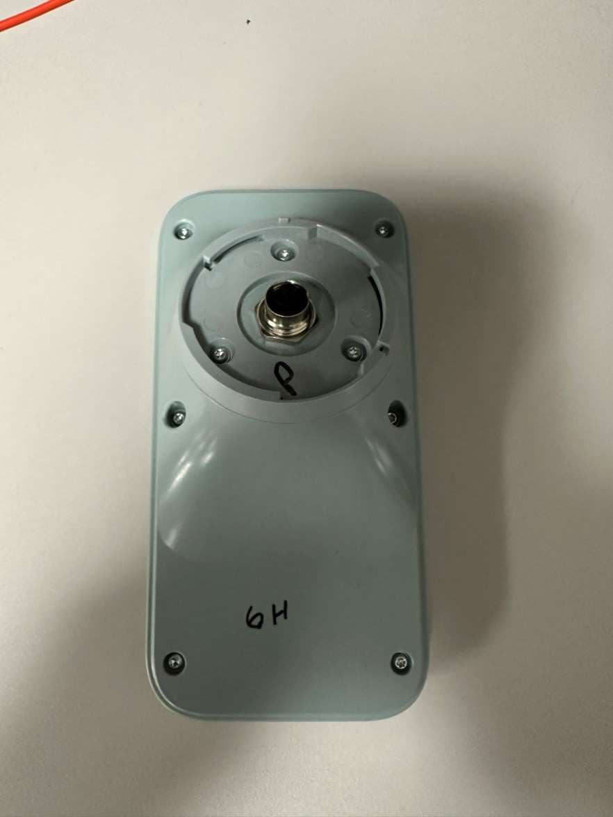
VDE-GGCAC
Apr 18, 2024Generator connectivity accessory
Equipment Class
PCB - PCS Licensed Transmitter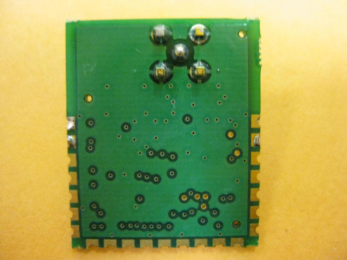
VDE-0H7699
Dec 08, 2010Generator Monitor Module
Equipment Class
DXX - Part 15 Low Power Communication Device Transmitter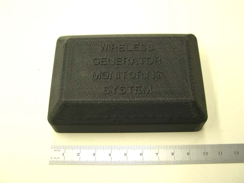
VDE0G6019
Sep 26, 20072.4GHz Wireless Transceiver
Equipment Class
DTS - Digital Transmission System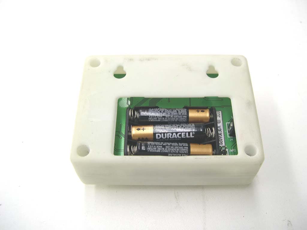
VDE0G6020
Sep 26, 20072.4GHz Wireless Transmitter
Equipment Class
DTS - Digital Transmission System