VDE-0H7699Generator Monitor Module
Generac Power Systems Inc.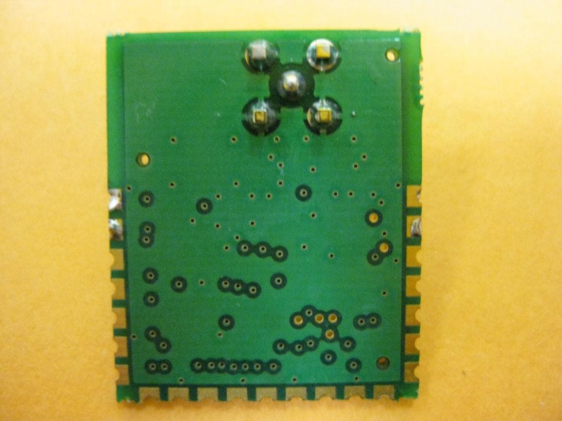
Click to zoom
Application Details
- Equipment Class
- DXX - Part 15 Low Power Communication Device Transmitter
- Date of Grant
- Dec 08, 2010
- Application Purpose
- Original Equipment
- Date of Application
- Dec 08, 2010
- Equipment Note
- Generator Monitor Module
- Frequency Range
- 907.00000000 - 923.00000000
- Company
- Generac Power Systems Inc.
- Country
- United States
Documents & Files
Document Text
Text extracted from the exhibit documents filed with the FCC. Open a document above to read the original.
Users Manual
Generac 0H7699 Wireless Module: Data Sheet/Manual 0H7699 module with connector for external antenna (see approved antennas listed below). 0H7699 module for wire antenna (see approved antennas listed below). November 2, 2010 Page 2 Compliance Statement (Part 15.19) This device complies with Part 15 of the FCC Rules. Operation is subject to the following two conditions: 1. This device may not cause harmful interference, and 2. This device must accept any interference received, including interference that may cause undesired operation. Warning (Part 15.21) Changes or modifications not expressly approved by the party responsible for compliance could void the user’s authority to operate the equipment. FCC Interference Statement (Part 15.105 (b) This equipment has been tested and found to comply with the limits for a Class B digital device, pursuant to Part 15 of the FCC Rules. These limits are designed to provide reasonable protection against harmful interference in a residential installation. This equipment generates uses and can radiate radio frequency energy and, if not installed and used in accordance with the instructions, may cause harmful interference to radio communications. However, there is no guarantee that interference will not occur in a particular installation. If this equipment does cause harmful interference to radio or television reception, which can be determined by turning the equipment off and on, the user is encouraged to try to correct the interference by one of the following measures: - Reorient or relocate the receiving antenna. - Increase the separation between the equipment and receiver. - Connect the equipment into an outlet on a circuit different from that to which the receiver is connected. - Consult the dealer or an experienced radio/TV technician for help. This portable transmitter with its antenna complies with FCC/IC RF exposure limits for general population / uncontrolled exposure. November 2, 2010 Page 3 Section 7.1.5 of RSS-GEN Operation is subject to the following two conditions: 1) this device may not cause interference, and 2) this device must accept any interference, including interference that may cause undesired operation of the device. Section 7.1.4 of RSS-GEN This device has been designed to operate with the antenna(s) listed below, and having a maximum gain of 2.0 dB. Antennas not included in this list or having a gain greater than 2.0 dB are strictly prohibited for use with this device. The required antenna impedance is 50 ohms. List of all Antennas Acceptable for use with the Transmitter 20AWG Insulated tinned-Cu wire 3.82in (97.0mm). Nearson S467AH-915 (SMA rev polarity). Section 7.1.5 of RSS-GEN To reduce potential radio interference to other users, the antenna type and its gain should be so chosen that the equivalent isotropically radiated power (e.i.r.p.) is not more than that permitted for successful communication. Federal Communication Commission Interference Statement This equipment has been tested and found to comply with the limits for a Class B digital device, pursuant to Part 15 of the FCC Rules. These limits are designed to provide reasonable protection against harmful interference in a residential installation. This equipment generates uses and can radiate radio frequency energy and, if not installed and used in accordance with the instructions, may cause harmful interference to radio communications. However, there is no guarantee that interference will not occur in a particular installation. If this equipment does cause harmful interference to radio or television reception, which can be determined by turning the equipment off and on, the user is encouraged to try to correct the interference by one of the following measures: - Reorient or relocate the receiving antenna. - Increase the separation between the equipment and receiver. - Connect the equipment into an outlet on a circuit different from that to which the receiver is connected. - Consult the dealer or an experienced radio/TV technician for help. November 2, 2010 Page 4 This device complies with Part 15 of the FCC Rules. Operation is subject to the following two conditions: (1) This device may not cause harmful interference, and (2) this device must accept any interference received, including interference that may cause undesired operation. FCC Caution : Any changes or modifications not expressly approved by the party responsible for compliance could void the user's authority to operate this equipment. INDUSTRY CANADA STATEMENTS Operation is subject to the following two conditions: (1) this device may not cause interference, and (2) this device must accept any interference, including interference that may cause undesired operation of the device. To reduce potential radio interference to other users, the antenna type and its gain should be so chosen that the equivalent isotropically radiated power (e.i.r.p.) is not more than that permitted for successful communication. This device has been designed to operate with the antennas listed below , and having a maximum gain of 2.0 dB. Antennas not included in this list or having a gain greater than 2.0 dB are strictly prohibited for use with this device. The required antenna impedance is 50 ohms. List of all Antennas Acceptable for use with the Transmitter 20AWG Insulated tinned-Cu wire 3.82in (97.0mm). Nearson S467AH-915 (SMA rev polarity). OEM Responsibilities to comply with FCC and Industry Canada Regulations The 0H7699 Module has been certified for integration into products only by OEM integrators under the following conditions: 1. The transmitter module must not be co-located or operating in conjunction with any other antenna or transmitter. As long as the two conditions above are met, further transmitter testing will not be required. However, the OEM integrator is still responsible for testing their end-product for any additional compliance requirements required with this module installed (for example, digital device …
Text truncated - open the document above for the full version.
External Photos
EXTERNAL PHOTOS Company Name Generac Model # 0H7699 FCC ID # VDE-0H7699 IC # 8036A-0H7699 Rubber Duck and Black Box External Photos Page 1 of 6 Board with Dipole antenna Dipole antenna side connections (picture 1) EXTERNAL PHOTOS Company Name Generac Model # 0H7699 FCC ID # VDE-0H7699 IC # 8036A-0H7699 Rubber Duck and Black Box External Photos Page 2 of 6 Dipole antenna side connections (picture 2) Dipole antenna side connections (picture 3) EXTERNAL PHOTOS Company Name Generac Model # 0H7699 FCC ID # VDE-0H7699 IC # 8036A-0H7699 Rubber Duck and Black Box External Photos Page 3 of 6 Dipole antenna board side connections Dipole antenna board side connections (picture 1) EXTERNAL PHOTOS Company Name Generac Model # 0H7699 FCC ID # VDE-0H7699 IC # 8036A-0H7699 Rubber Duck and Black Box External Photos Page 4 of 6 Dipole antenna board side connections (picture 2) Dipole antenna board side connections (picture 3) EXTERNAL PHOTOS Company Name Generac Model # 0H7699 FCC ID # VDE-0H7699 IC # 8036A-0H7699 Rubber Duck and Black Box External Photos Page 5 of 6 Board with custom wire antenna EXTERNAL PHOTOS Company Name Generac Model # 0H7699 FCC ID # VDE-0H7699 IC # 8036A-0H7699 Rubber Duck and Black Box External Photos Page 6 of 6 Back Side of Board
ID Label/Location Info
Generac ID Label Photos
Internal Photos
INTERNAL PHOTOS Company Name Generac Model # 0H7699 FCC ID # VDE‐0H7699 IC # 8036A‐0H7699 Page 1 of 2 INTERNAL PHOTOS Company Name Generac Model # 0H7699 FCC ID # VDE‐0H7699 IC # 8036A‐0H7699 Page 2 of 2
Test Report
LS Research, LLC Cert. # 1255.01 W66 N220 Commerce Court ● Cedarburg, WI 53012 ● USA Phone: 262.375.4400 ● Fax: 262.375.4248 www.lsr.com COMPLIANCE TESTING OF: 900 MHz Module with External Dipole PREPARED FOR: Generac Power Systems Attn: Steve Wilcox Hwy. 59 & Hillside Road P.O. Box 8 Waukesha, WI 53187 TEST REPORT NUMBER: 310068 LSR Job #: C-844 TEST DATE(S): July 2, 5, 6, 8, 9, 12-15, and December 2, 2010 All results of this report relate only to the items that were tested. This report is not to be reproduced, except in full, without written approval of LS Research, LLC. LS Research, LLC Page 2 of 35 Test Report Number: Prepared For: Table of Contents Section Description Page Index 2 1 LS Research, LLC in Review 3 2 Signature Page 4 3 Product and General Information 5 4 Introduction 5 5 Product Description 5 6 EUT Technical Specifications 6 7 Test Requirements 6 8 Summary of Test Report 8 9 Radiated Emissions Test 9 10 RX Mode Test Results 19 11 Band-Edge Measurements 22 12 Frequency and Power Stability across input voltage 23 13 Conducted AC Line Emissions 24 14 Conducted Occupied Bandwidth 31 Appendix A Test Equipment List 33 B Test Standards List 34 C Uncertainty Statement 35 LS Research, LLC Page 3 of 35 Test Report Number: Prepared For: 1. LS Research, LLC In Review LS Research, LLC - Accreditations and Listing’s As an EMC Testing Laboratory, our Accreditation and Assessments are recognized through the following: A2LA – American Association for Laboratory Accreditation Accreditation based on ISO/IEC 17025 : 2005 with Electrical (EMC) Scope of Accreditation A2LA Certificate Number: 1255.01 Federal Communications Commission (FCC) – USA Listing of 3 Meter Semi-Anechoic Chamber based on Title 47 CFR – Part 2.948 FCC Registration Number: 90756 Industry Canada On file, 3 Meter Semi-Anechoic Chamber based on RSS-212 – Issue 1 File Number: IC 3088-A On file, 3 and 10 Meter OATS based on RSS-212 – Issue 1 File Number: IC 3088 U. S. Conformity Assessment Body (CAB) Validation Validated by the European Commission as a U. S. Competent Body operating under the U. S. /EU, Mutual Recognition Agreement (MRA) operating under the European Union Electromagnetic Compatibility –Council Directive 2004/108/EC (formerly 89/336/EEC, Article 10.2) Date of Validation: January 16, 2001 Validated by the European Commission as a U.S. Notified Body operating under the U.S./EU, Mutual Recognition Agreement (MRA) operating under the European Union Telecommunication Equipment – Council Directive 99/5/EC, Annex V. Date of Validation: November 20, 2002 Notified Body Identification Number: 1243 2. Signature Page Reviewed By: 08.16.10 Thomas T. Smith, Manager EMC Test Services Date Tested By: 08.16.10 Peter Feilen, EMC Engineer Date Approved By: 08.16.10 Thomas T. Smith, Manager EMC Test Services Date LS Research, LLC Page 4 of 35 Test Report Number: Prepared For: LS Research, LLC Page 5 of 35 Test Report Number: Prepared For: 3. Product and General Information Manufacturer: Generac Power Systems Date(s) of Test: July 2, 5, 6, 8, 9, 12-15, 2010 Test Engineer(s): X Peter Feilen Model #: 0H7699 Serial #: N/A Voltage: 3.3 VDC Operation Mode: Normal 4. Introduction On July 2, 5, 6, 8, 9, 12-15, 2010 a series of Conducted and Radiated Emission tests were performed on one sample of the 900 MHz Module, Model Number 0H7699, here forth referred to as the “Equipment Under Test” or “EUT”. These tests were performed using the procedures outlined in ANSI C63.4-2003 for intentional radiators, and in accordance with the limits set forth in FCC Part 15.249 (Industry Canada RSS-210, Issue 7, 2007) for a low power transmitter. These tests were performed by Peter Feilen, EMC Engineer of LS Research. All Radiated and Conducted Emission tests were performed upon the EUT to measure the emissions in the frequency bands described in FCC Title 47 CFR Part 15, including 15.35, 15.209, 15.249 and Industry Canada RSS-210, Issue 7, 2007 to determine whether these emissions are below the limits expressed within the standards. These tests were performed in accordance with the procedures described in the American National Standard for methods of measurement of Radio-Noise Emissions from Low-Voltage Electrical and Electronic Equipment in the Range of 9 kHz to 40 GHz (ANSI C63.4-2003). Another document used as a reference for the EMI Receiver specification was the Comite International Special Des Perturbations Radioelelectriques (CISPR) Number 16-1, 2003. 5. Product Description The 900 MHz Radio with Dipole antenna is designed to be used with the 2 dBi dipole associated with testing. This antenna is detachable and the unit with antenna attached is portable for use in different applications for communicating information on generator status. LS Research, LLC Page 6 of 35 Test Report Number: Prepared For: 6. EUT’S TECHNICAL SPECIFICATIONS Additional Information : Frequency Range (in MHz) 907-923 MHz RF Power in Watts 0.000082 W Conducted Output Power (in dBm) -10.84 dBm EIRP (in mW) 0.131 mW Field Strength (and at what distance) 89.3 dBuV/m @ 3m (907 MHz) 90.1 dBuV/m @ 3m (917 MHz) 90.4 dBuV/m @ 3m (923 MHz) Occupied Bandwidth (99% BW) 288.84 kHz Type of Modulation FSK Emission Designator 289KF1D Transmitter Spurious (worst case) 50.5 dBuV/m @ 3m @ 1814 MHz Receiver Spurious (worst case) 56.9 dBuV/m @ 1 m @ 8487 MHz Frequency Tolerance %, Hz, ppm Better than 100 ppm Microprocessor Model # (if applicable) Microchip PIC16F1936-I/SS EUT will be operated under FCC Rule Part(s) 15.249 Antenna Information: a) Antenna Type Nearson S467AH-915 b) Detachable/Non-Detachable Detachable c) Antenna Gain (in dBi) +2 dBi Modular Filing Yes No Portable/Mobile Portable Mobile RF Technical Information: Type of Evaluation (check one) SAR Evaluation: Device Used in the Vicinity of the Human Head SAR Evaluation: Body-worn Device X RF Evaluation If RF Evaluation checked above, test engineer to complete the following: Evaluated against exposure limits: General Public Use Cont…
Text truncated - open the document above for the full version.
Test Report
LS Research, LLC Cert. # 1255.01 W66 N220 Commerce Court ● Cedarburg, WI 53012 ● USA Phone: 262.375.4400 ● Fax: 262.375.4248 www.lsr.com COMPLIANCE TESTING OF: Generac 900 MHz Module with Wire Antenna PREPARED FOR: Generac Attn: Steve Wilcox Hwy. 59 & Hillside Road P.O. Box 8 Waukesha, WI 53187 TEST REPORT NUMBER: 310068 LSR Job #: C-844 TEST DATE(S): July 2, 5, 6, 8, 9, 12-15, and December 2, 2010 All results of this report relate only to the items that were tested. This report is not to be reproduced, except in full, without written approval of LS Research, LLC. LS Research, LLC Page 2 of 34 Test Report Number: Prepared For: Table of Contents Section Description Page Index 2 1 LS Research, LLC in Review 3 2 Signature Page 4 3 Product and General Information 5 4 Introduction 5 5 Product Description 5 6 EUT Technical Specifications 6 7 Test Requirements 8 8 Summary of Test Report 8 9 Radiated Emissions Test 9 10 RX Mode Test Results 19 11 Band-Edge Measurements 22 12 Frequency and Power Stability across input voltage 23 13 Conducted AC Line Emissions 24 14 Conducted Occupied Bandwidth 30 Appendix A Test Equipment List 32 B Test Standards List 33 C Uncertainty Statement 34 LS Research, LLC Page 3 of 34 Test Report Number: Prepared For: 1. LS Research, LLC In Review LS Research, LLC - Accreditations and Listing’s As an EMC Testing Laboratory, our Accreditation and Assessments are recognized through the following: A2LA – American Association for Laboratory Accreditation Accreditation based on ISO/IEC 17025 : 2005 with Electrical (EMC) Scope of Accreditation A2LA Certificate Number: 1255.01 Federal Communications Commission (FCC) – USA Listing of 3 Meter Semi-Anechoic Chamber based on Title 47 CFR – Part 2.948 FCC Registration Number: 90756 Industry Canada On file, 3 Meter Semi-Anechoic Chamber based on RSS-212 – Issue 1 File Number: IC 3088-A On file, 3 and 10 Meter OATS based on RSS-212 – Issue 1 File Number: IC 3088 U. S. Conformity Assessment Body (CAB) Validation Validated by the European Commission as a U. S. Competent Body operating under the U. S. /EU, Mutual Recognition Agreement (MRA) operating under the European Union Electromagnetic Compatibility –Council Directive 2004/108/EC (formerly 89/336/EEC, Article 10.2) Date of Validation: January 16, 2001 Validated by the European Commission as a U.S. Notified Body operating under the U.S./EU, Mutual Recognition Agreement (MRA) operating under the European Union Telecommunication Equipment – Council Directive 99/5/EC, Annex V. Date of Validation: November 20, 2002 Notified Body Identification Number: 1243 2. Signature Page Reviewed By: 08.16.10 Thomas T. Smith, Manager EMC Test Services Date Tested By: 08.16.10 LS Research, LLC Page 4 of 34 Test Report Number: Prepared For: Peter Feilen, EMC Engineer Date Approved By: 08.16.10 Thomas T. Smith, Manager EMC Test Services Date LS Research, LLC Page 5 of 34 Test Report Number: Prepared For: 3. Product and General Information Manufacturer: Generac Date(s) of Test: July 2, 5, 6, 8, 9, 12-15, 2010 Test Engineer(s): X Peter Feilen Model #: 0H7699 Serial #: N/A Voltage: 3.3 VDC Operation Mode: Normal 4. Introduction On July 2, 5, 6, 8, 9, 12-15, and December 2, 2010 a series of Conducted and Radiated Emission tests were performed on one sample of the 900 MHz Module, Model Number 0H7699, here forth referred to as the “Equipment Under Test” or “EUT”. These tests were performed using the procedures outlined in ANSI C63.4-2003 for intentional radiators, and in accordance with the limits set forth in FCC Part 15.249 (Industry Canada RSS-210, Issue 7, 2007) for a low power transmitter. These tests were performed by Peter Feilen, EMC Engineer of LS Research. All Radiated and Conducted Emission tests were performed upon the EUT to measure the emissions in the frequency bands described in FCC Title 47 CFR Part 15, including 15.35, 15.209, 15.249 and Industry Canada RSS-210, Issue 7, 2007 to determine whether these emissions are below the limits expressed within the standards. These tests were performed in accordance with the procedures described in the American National Standard for methods of measurement of Radio-Noise Emissions from Low-Voltage Electrical and Electronic Equipment in the Range of 9 kHz to 40 GHz (ANSI C63.4-2003). Another document used as a reference for the EMI Receiver specification was the Comite International Special Des Perturbations Radioelelectriques (CISPR) Number 16-1, 2003. 5. Product Description The 900 MHz Radio with Dipole antenna is designed to be used with a wire antenna. This antenna is detachable and the unit with antenna attached is portable for use in different applications for communicating information on generator status. LS Research, LLC Page 6 of 34 Test Report Number: Prepared For: 6. EUT’S TECHNICAL SPECIFICATIONS Additional Information : Frequency Range (in MHz) 907-923 MHz RF Power in Watts 0.000082 W Conducted Output Power (in dBm) -10.84 dBm EIRP (in mW) 0.131 mW Field Strength (and at what distance) 93.8 dBuV/m @ 3m (907 MHz) 93.6 dBuV/m @ 3m (917 MHz) 91.7 dBuV/m @ 3m (923 MHz) Occupied Bandwidth (99% BW) 288.84 kHz Type of Modulation FSK Emission Designator 289KF1D Transmitter Spurious (worst case) 52.1 dBuV/m @ 1834 MHz (@ 1m) Receiver Spurious (worst case) 56.9 dBuV/m @ 8573 MHz (@ 1m) Frequency Tolerance %, Hz, ppm Better than 100 ppm Microprocessor Model # (if applicable) Microchip PIC16F1936-I/SS EUT will be operated under FCC Rule Part(s) 15.249 Antenna Information: a) Antenna Type Custom designed wire antenna b) Detachable/Non-Detachable Non-Detachable c) Antenna Gain (in dBi) 9.41 dBi Modular Filing Yes No Portable/Mobile Portable Mobile RF Technical Information: Type of Evaluation (check one) SAR Evaluation: Device Used in the Vicinity of the Human Head SAR Evaluation: Body-worn Device X RF Evaluation If RF Evaluation checked above, test engineer to complete the following: Evaluated against exposure limits: General Public Use Controlled Use D…
Text truncated - open the document above for the full version.
Test Setup Photos
TEST SETUP PHOTOS Company Name Generac Model # 0H7699 FCC ID # VDE-0H7699 IC # 8036A-0H7699 Page 1 of 6 DIPOLE ANTENNA PHOTOS Setup for the Radiated Emissions Test TEST SETUP PHOTOS Company Name Generac Model # 0H7699 FCC ID # VDE-0H7699 IC # 8036A-0H7699 Page 2 of 6 TEST SETUP PHOTOS Company Name Generac Model # 0H7699 FCC ID # VDE-0H7699 IC # 8036A-0H7699 Page 3 of 6 TEST SETUP PHOTOS Company Name Generac Model # 0H7699 FCC ID # VDE-0H7699 IC # 8036A-0H7699 Page 4 of 6 Wire Antenna Photos Setup for the Radiated Emissions Test TEST SETUP PHOTOS Company Name Generac Model # 0H7699 FCC ID # VDE-0H7699 IC # 8036A-0H7699 Page 5 of 6 TEST SETUP PHOTOS Company Name Generac Model # 0H7699 FCC ID # VDE-0H7699 IC # 8036A-0H7699 Page 6 of 6 LS Research, LLC Page 27 of 33 Test Report Number: Prepared For: 13.7 Test Setup Photo(s) – Conducted Emissions Test LS Research, LLC Page 28 of 33 Test Report Number: Prepared For: LS Research, LLC Page 27 of 32 Test Report Number: Prepared For: 13.7 Test Setup Photo(s) – Conducted Emissions Test
Contact Information
Applicant
Jeffrey Jonas(Senior Staff Engineer)
Test Firm
LS Research, LLCRyan Urness
Technical Specifications
| # | Rule Parts | Frequency Range | Power Output |
|---|---|---|---|
| 1 | 15C | 907 MHz - 923 MHz | - |
Other Applications from Generac Power Systems Inc.
VDE-GGCAC
Apr 18, 2024Generator connectivity accessory
Equipment Class
PCB - PCS Licensed Transmitter
VDE-0G6019B
Feb 01, 2010Generator Transceiver
Equipment Class
DTS - Digital Transmission System
VDE0G6019
Sep 26, 20072.4GHz Wireless Transceiver
Equipment Class
DTS - Digital Transmission System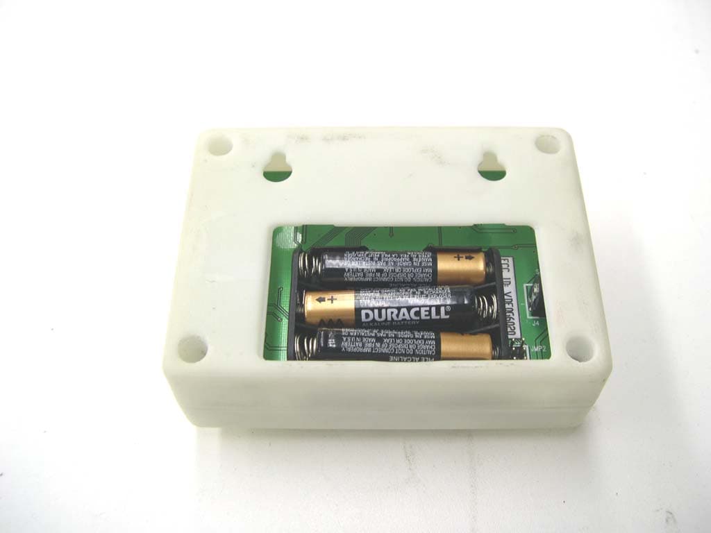
VDE0G6020
Sep 26, 20072.4GHz Wireless Transmitter
Equipment Class
DTS - Digital Transmission System