VDE0G60192.4GHz Wireless Transceiver
Generac Power Systems Inc.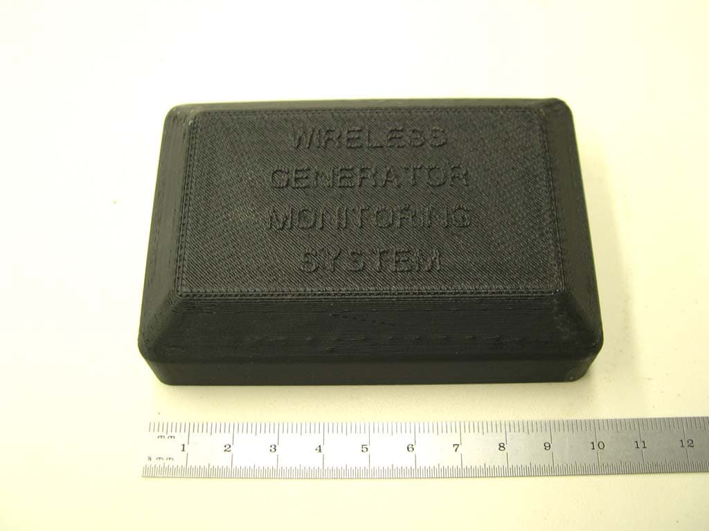
Click to zoom
Application Details
- Equipment Class
- DTS - Digital Transmission System
- Date of Grant
- Sep 26, 2007
- Application Purpose
- Original Equipment
- Date of Application
- Sep 26, 2007
- Equipment Note
- 2.4GHz Wireless Transceiver
- Frequency Range
- 2405.00000000 - 2480.00000000
- Company
- Generac Power Systems Inc.
- Country
- United States
Documents & Files
Document Text
Text extracted from the exhibit documents filed with the FCC. Open a document above to read the original.
Users Manual
Generac Wireless Display System Instruction Manual Preliminary Proof #2 07/20/07 TABLE OF CONTENTS SAFETY ...................................... Inside Front Cover Read This Manual Thoroughly ..................... IFC Operation and Maintenance ............................ 3 How to Obtain Service ..................................... 3 INTRODUCTION .................................................... 3 BATTERY OPERATION .......................................... 3 INSTALLATION ...................................................... 4 THE COMMUNICATIONS LED ............................... 5 GENERATOR COMMUNICATIONS ......................... 5 THE DISPLAY ........................................................ 5 Contrast Adjustment ....................................... 5 Backlight ......................................................... 5 Buttons............................................................ 5 Battery and Signal Strength Indicators............ 5 ALARM AND STATUS DISPLAY ............................. 6 THE MENU SYSTEM ............................................. 6 Status Menu .................................................... 6 Test Menu ........................................................ 6 History Menu ................................................... 7 Email Menu ..................................................... 7 SETTINGS MENU .................................................. 7 Adjust Contrast ............................................... 7 VAC Threshold ................................................ 7 Service Schedule ............................................. 7 EXERCISE MENU .................................................. 7 RADIO MENU......................................................... 8 Radio information ........................................... 8 Changing Channels .......................................... 8 Reset Radio ..................................................... 8 Add New Display ............................................. 8 Test Radio Link ............................................... 9 TIME & DATE MENU ............................................. 9 GRAPH MENU ....................................................... 9 MENU MAP ............................................ Back Cover SAFETY This device complies with Part 15 of the FCC Rules. Operation is subject to the following conditions: This device may not cause harmful interference. This device must accept any interference received, including interference that may cause undesired operation. READ THIS MANUAL THOROUGHLY If any portion of this manual is not understood, con- tact the nearest Authorized Service Dealer for start- ing, operating and servicing procedures. Throughout this publication, and on tags and decals affixed to the generator, DANGER, WARNING, CAUTION and NOTE blocks are used to alert person- nel to special instructions about a particular service or operation that may be hazardous if performed incorrectly or carelessly. Observe them carefully. Their definitions are as follows: DANGER After this heading, read instructions that, if not strictly complied with, will result in personal injury or property damage. After this heading, read instructions that, if not strictly complied with, may result in personal inju- ry or property damage. After this heading, read instructions that, if not strictly complied with, could result in damage to equipment and/or property. NOTE: After this heading, read explanatory statements that require special emphasis. These safety warnings cannot eliminate the hazards that they indicate. Common sense and strict compli- ance with the special instructions while performing the service are essential to preventing accidents. Four commonly used safety symbols accompany the DANGER, WARNING and CAUTION blocks. The type of information each indicates is as follows: This symbol points out important safety informa- tion that, if not followed, could endanger personal safety and/or property of others. This symbol points out potential explosion hazard. • • Table of Contents Wireless Display System 1 This symbol points out potential fire hazard. This symbol points out potential electrical shock hazard. Study these SAFETY RULES carefully before install- ing, operating or servicing this equipment. Become familiar with this Owner’s Manual and with the unit. The generator can operate safely, efficiently and reli- ably only if it is properly installed, operated and maintained. Many accidents are caused by failing to follow simple and fundamental rules or precautions. The manufacturer cannot anticipate every possible circumstance that might involve a hazard. The warn- ings in this manual, and on tags and decals affixed to the unit are, therefore, not all inclusive. If using a procedure, work method or operating technique that the manufacturer does not specifically recommend, ensure that it is safe for all personnel. Also make sure the procedure, work method or operating technique utilized does not render the generator unsafe. DANGER Despite the safe design of this generator, operating this equipment imprudently, neglect- ing its maintenance or being careless can cause possible injury or death. Permit only responsible and capable persons to install, operate or main- tain this equipment. Potentially lethal voltages are generated by these machines. Ensure all steps are taken to render the machine safe before attempting to work on the generator. Parts of the generator are rotating and/or hot during operation. Exercise care near running generators. GENERAL HAZARDS For safety reasons, the manufacuter recommends that this equipment be installed, serviced and repaired by an Authorized Service Dealer or other competent, qualified electrician or installation tech- nician who is familiar with applicable codes, stan- dards and regulations. The operator also must com- ply with all such codes, standards and regulations. Installation, operation, se…
Text truncated - open the document above for the full version.
Cover Letter(s)
FCC ID: Request for Confidentiality In accordance with 47 C.F.R. Section 0.459, we, Generac Power Systems Inc., hereby request confidentiality for the block diagram, schematic and product description presented for certification. In support of the Request for Confidentiality, the following is stated: Enclosed within this application is technical information which we deem to be trade secrets and proprietary. If made public, the information might be used to our disadvantage. To assist in assuring that we receive the full value of our product and protect its competitive posture, we respectfully request this grant of confidentiality. Steve Wilcox Generac Power Systems Inc.
External Photos
0G6019:Front view of case.
Internal Photos
0G6019: PCB assembly (component side).
Internal Photos
0G6019: PCB assembly (component side).
Internal Photos
0G6019: PCB assembly (non-component side).
Internal Photos
0G6019: PCB assembly (non-component side).
Internal Photos
0G6019: PCB mounted in case.
Internal Photos
0G6019: PCB mounted in case.
Test Report
Engineering Test Report No. 38338-02 Measurement of RF Interference from a Model No. 0G6019 End Unit Transceiver For : Generac Power Systems : PO Box 8 : Waukesha, WI P.O. No. : 70010 Date Received : May 29, 2007 Date Tested : May 29, 2007 through June 1, 2007 Test Personnel : Daniel E. Crowder Specification : FCC "Code of Federal Regulations" Title 47, Part 15, Subpart B and Subpart C, Section 15.247 for Digital Transmission Systems Operating within The band 2400- 2483.5MHz Industry Canada RSS-210 Industry Canada RSS-GEN Test Report By : Daniel E. Crowder Witnessed By : Steve Wilcox Generac Power Systems Approved By : Raymond J. Klouda Registered Professional Engineer of Illinois - 44894 Elite Electronic Engineering Inc. 1516 Centre Circle Downers Grove, IL 60515 Tel : (630) 495-9770 Fax: (630) 495-9785 www.elitetest.com Engineering Test Report No. 38338-02 THIS REPORT SHALL NOT BE REPRODUCED, EXCEPT IN FULL, WITHOUT THE WRITTEN APPROVAL OF ELITE ELECTRONIC ENGINEERING INCORPORATED. Page 2 of 53 TABLE OF CONTENTS PARAGRAPH DESCRIPTION OF CONTENTS PAGE NO. 1 INTRODUCTION ............................................................................................................................................... 5 1.1 Scope of Tests .......................................................................................................................................... 5 1.2 Purpose .................................................................................................................................................... 5 1.3 Deviations, Additions and Exclusions....................................................................................................... 5 1.4 EMC Laboratory Identification .................................................................................................................. 5 1.5 Laboratory Conditions .............................................................................................................................. 5 2 APPLICABLE DOCUMENTS ............................................................................................................................ 5 3 TEST ITEM SET-UP AND OPERATION .......................................................................................................... 6 3.1 General Description .................................................................................................................................. 6 3.1.1 Power Input .......................................................................................................................................... 6 3.1.2 Peripheral Equipment........................................................................................................................... 6 3.1.3 Interconnect Cables ............................................................................................................................. 6 3.1.4 Grounding............................................................................................................................................. 6 3.2 Operational Mode ..................................................................................................................................... 6 3.3 Test Item Modifications............................................................................................................................. 6 4 TEST FACILITY AND TEST INSTRUMENTATION.......................................................................................... 6 4.1 Shielded Enclosure................................................................................................................................... 6 4.2 Test Instrumentation ................................................................................................................................. 6 4.3 Calibration Traceability ............................................................................................................................. 7 4.4 Measurement Uncertainty ........................................................................................................................ 7 5 TEST PROCEDURES ....................................................................................................................................... 7 5.1 Powerline Conducted Emissions .............................................................................................................. 7 5.1.1 Receiver ............................................................................................................................................... 7 5.1.2 Transmitter ........................................................................................................................................... 7 5.2 Spurious Measurements........................................................................................................................... 7 5.2.1 Receiver ............................................................................................................................................... 7 5.2.2 Transmitter Antenna Conducted ............................................................................................ .............. 7 5.2.3 Transmitter Radiated Spurious Emissions ........................................................................................... 8 5.3 6dB Bandwidth and 99% Bandwidth ........................................................................................................ 9 5.3.1 Requirements ....................................................................................................................................... 9 5.3.2 Procedures ......................................................................................................................................... 10 5.3.3 Results................................................................................................................................................ 10 5.4 Peak Ou…
Text truncated - open the document above for the full version.
Contact Information
Applicant
Jeffrey Jonas(Senior Staff Engineer)
Test Firm
Elite Electronic Engineering Inc.Kevin Halpin
Technical Specifications
| # | Rule Parts | Frequency Range | Power Output |
|---|---|---|---|
| 1 | 15C | 2.40 GHz - 2.48 GHz | 4.00 mW |
Other Applications from Generac Power Systems Inc.
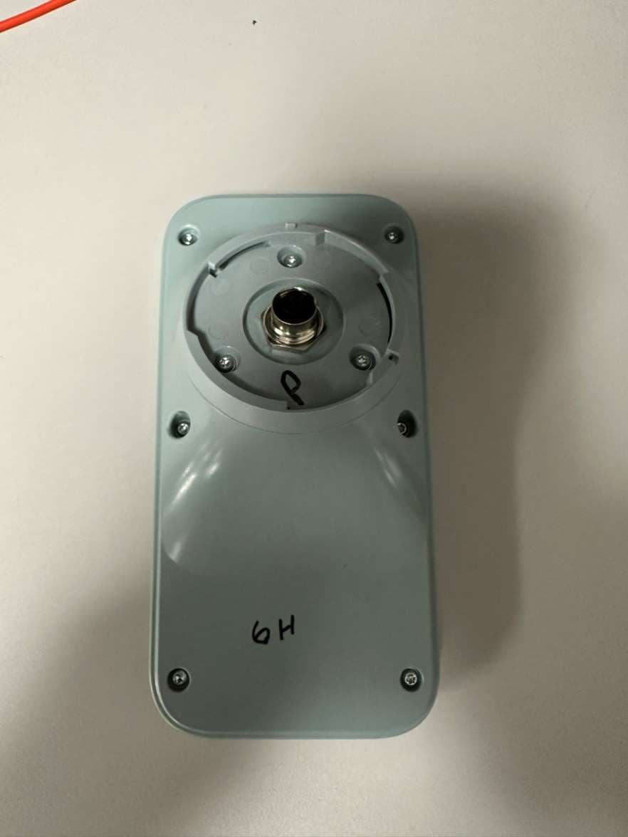
VDE-GGCAC
Apr 18, 2024Generator connectivity accessory
Equipment Class
PCB - PCS Licensed Transmitter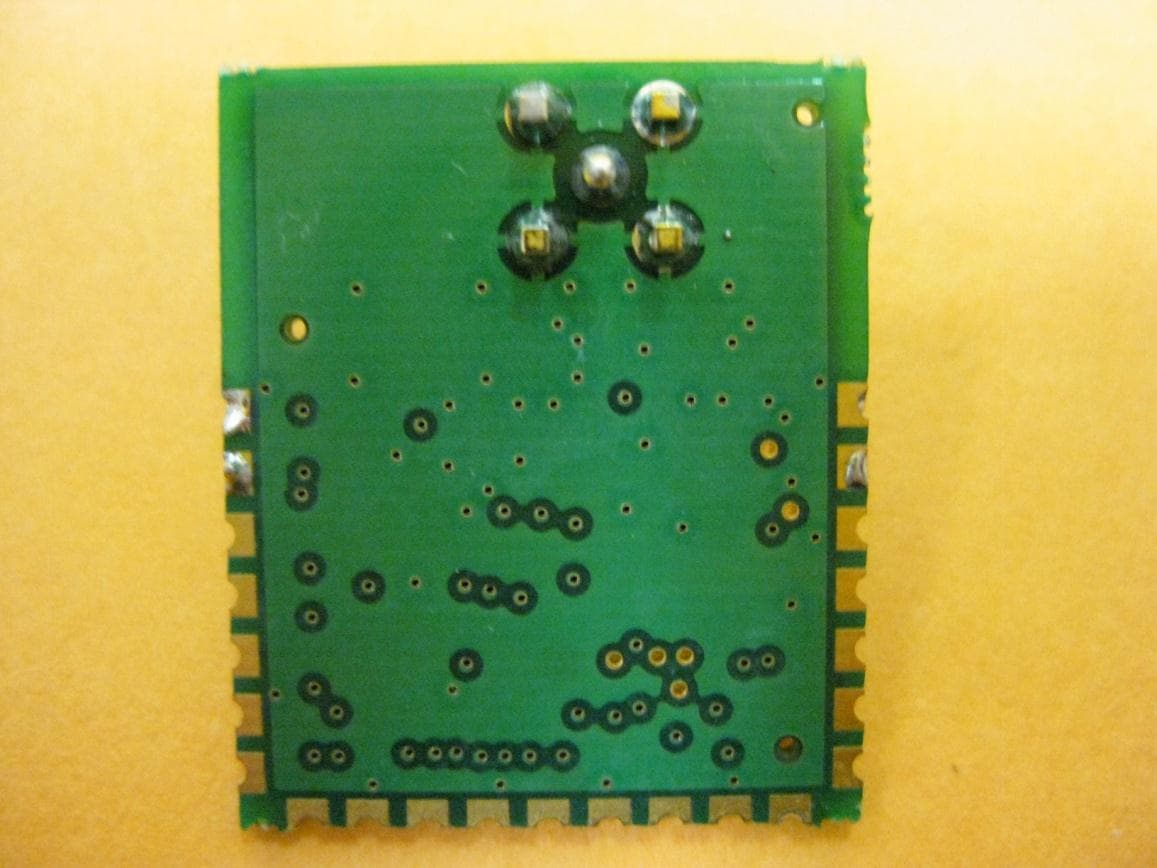
VDE-0H7699
Dec 08, 2010Generator Monitor Module
Equipment Class
DXX - Part 15 Low Power Communication Device Transmitter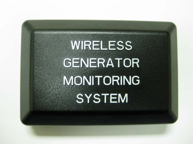
VDE-0G6019B
Feb 01, 2010Generator Transceiver
Equipment Class
DTS - Digital Transmission System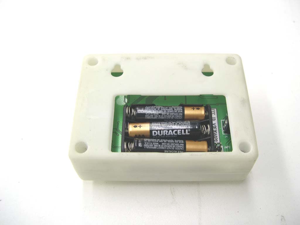
VDE0G6020
Sep 26, 20072.4GHz Wireless Transmitter
Equipment Class
DTS - Digital Transmission System