VEP-SCPCAM-TFTWifi Optical Scope Cam
K-Mark Industrial Limited.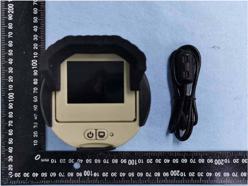
Click to zoom
Application Details
- Equipment Class
- DTS - Digital Transmission System
- Date of Grant
- Feb 17, 2020
- Application Purpose
- Original Equipment
- Date of Application
- Feb 17, 2020
- Equipment Note
- Wifi Optical Scope Cam
- Frequency Range
- 2412.00000000 - 2462.00000000
- Company
- K-Mark Industrial Limited.
- Country
- Hong Kong
Documents & Files
Document Text
Text extracted from the exhibit documents filed with the FCC. Open a document above to read the original.
Users Manual
1 SME-SCPCAM-TFT 2 Thank you for purchasing the WF Scope Camera with Screen In cluded: *Spotting S cope sold s eparately* Scope Camera Carry Bag1m Micro USB Cable 3 Attaching to Spotting Scope Make sure gr ips inside ro tating chucks are full open. Rot ate lower ro tating chuck count er- clockwise (when vi ewing fr om bot tom) to open gr ips. Place W FScope camera over eyepiece of spotting scope. SME Scope Cameras will fit eyepieces with diameters in range of 1” – 2.25 ” Rotate lower rotating chuck counter- clockwise (when viewing from top) to close grips. 4 Screen Adjustments To maximize screen vi sibi lit y in di fferent lig ht conditions, see below opt ions: Tilt screen downward upto 15⁰by pulling forwardfrom top of screen Use screen button to adjust screen brightness while unit is ON. Continue pressing button to cycle through the following levels: 100% > 75% > 50% > 25% > OFF Micro SD Card With a Micro SD Card installed, the Spot Shot Scope will save images and videos capture via the Spot Shot App on the Micro SD Card. Insert micro SD card while unit is OFF. Insert with bottom facing up and the notch facing the lef t. 5 Download the SME SpotShot APP Download the SME Spot Shot APP from the Apple App Store or Google Play Store Power on the Scope Camera Connect to the SpotShot network as youwould any other network. Go to the settings on your mobile device and select theSpot Shot SSID and Password are locatedon the bottom of the screen for 5 seconds afterthe unit is powered ON. (To change thepassword, hold the POWER and SCREEN buttonfor 5 seconds) Launch the App and select Connect Make sure you are connecting to correct network. If correct, select Proceed. If not, select Settings to change 6 RF exposure statement This equipment complies with the FCC RF radiation exposure limits set forth for an uncontrolled environment. This equipment should be installed and operated with a minimum distance of 20cm between the radiator and any part of your body. This equipment meets the exemption from the routine evaluation limits in section 2.5 of RSS-102. It should be installed and operated with a minimum distance of 20cm between the radiator and any part of your body. FCC Warning FCC ID: VEP-SCPCAM-TFT This device complies with Part 15 of the FCC Rules. Operation is subject to the following two conditions: (1) This device may not cause harmful interference, and (2) this device must accept any interference received, including interference that may cause undesired operation. NOTE 1: This equipment has been tested and found to comply with the limits for a Class B digital device, pursuant to part 15 of the FCC Rules. These limits are designed to provide reasonable protection against harmful interference in a residential installation. This equipment generates, uses and can radiate radio frequency energy and, if not installed and used in accordance with the instructions, may cause harmful interference to radio communications. However, there is no guarantee that interference will not occur in a particular installation. If this equipment does cause harmful interference to radio or television reception, which can be determined by turning the equipment off and on, the user is encouraged to try to correct the interference by one or more of the following measures: - Reorient or relocate the receiving antenna. - Increase the separation between the equipment and receiver. -Connect the equipment into an outlet on a circuit different from that to which the receiver is connected. -Consult the dealer or an experienced radio/TV technician for help. NOTE 2: Any changes or modifications to this unit not expressly approved by the party responsible for compliance could void the user's authority to operate the equipment. 7 IC WARNING IC: 11708A-SCPCAMTFT This device contains licence-exempt transmitter(s) that comply with Innovation, Science and Economic Development Canada’s licence-exempt RSS(s). Operation is subject to the following two conditions: (1) This device may not cause interference. (2) This device must accept any interference, including interference that may cause undesired operation of the device. L’émetteur/récepteur exempt de licence contenu dans le présent appareil est conforme aux CNR d’Innovation, Sciences et Développement économique Canada applicables aux appareils radio exempts de licence. L’exploitation est autorisée aux deux conditions suivantes: 1. L’appareil ne doit pas produire de brouillage; 2. L’appareil doit accepter tout brouillage radioélectrique subi, même si le brouillage est susceptible d’en compromettre le fonctionnement. Li mited Warranty SME Spot Shot Pro Wi-Fi Scope Cameras are covered by a One Year Limited Warranty. This Warranty covers rangefi nders with manufacture defects. Nor mal wear & tear as well as pro duct abuse are not covered by the warranty. This Warranty is valid only for the original owner of the Wi-Fi Scope Camera purchased from an authorized retailer. Tampering with or altering the unit will void the warr ant y. Any unauthorized serv ice will void the warr ant y. Ori gi nal sales receipt must be produced for any warr anty serv ice and a Return Authorization (RA) number must be obtained from cust omer serv ice at 877-269-8490 prior to re turning the pro duct. For more information go to: www.shootingmadeeasy .com Patent Pendin g
External Photos
Model: SME-SCPCAM-TFT Report No.: WTX19X12086015W Page 2 of 15 FCC Part 15.247 EXHIBIT 2 - EUT EXTERNAL PHOTOGRAPHS EUT View 1 EUT View 2 Model: SME-SCPCAM-TFT Report No.: WTX19X12086015W Page 3 of 15 FCC Part 15.247 EUT View 3 EUT View 4 Model: SME-SCPCAM-TFT Report No.: WTX19X12086015W Page 4 of 15 FCC Part 15.247 EUT View 5 EUT View 6 Model: SME-SCPCAM-TFT Report No.: WTX19X12086015W Page 5 of 15 FCC Part 15.247 EUT View 7 EUT View 8
ID Label/Location Info
Model: SME-SCPCAM-TFT Report No.: WTX19X12086015W Page 1 of 15 FCC Part 15.247 EXHIBIT 1 - PRODUCT LABELING Proposed FCC ID Label Format Specifications: Text is black in color and justified. Labels are printed in indelible ink on permanent adhesive silk-screened onto the EUT or shall be affixed at a conspicuous location on the EUT. Proposed Label Location on EUT FCC ID Label Location
Internal Photos
Model: SME-SCPCAM-TFT Report No.: WTX19X12086015W Page 6 of 16 FCC Part 15.247 EXHIBIT 3 - EUT INTERNAL PHOTOGRAPHS EUT Housing and Board View 1 EUT Housing and Board View 2 Model: SME-SCPCAM-TFT Report No.: WTX19X12086015W Page 7 of 16 FCC Part 15.247 Solder Board-Component View 1 Solder Board-Component View 2 Model: SME-SCPCAM-TFT Report No.: WTX19X12086015W Page 8 of 16 FCC Part 15.247 Solder Board-Component View 3 Solder Board-Component View 4 Model: SME-SCPCAM-TFT Report No.: WTX19X12086015W Page 9 of 16 FCC Part 15.247 Solder Board-Component View 5 Solder Board-Component View 6 Model: SME-SCPCAM-TFT Report No.: WTX19X12086015W Page 10 of 16 FCC Part 15.247 Solder Board-Component View 7 Solder Board-Component View 8 Model: SME-SCPCAM-TFT Report No.: WTX19X12086015W Page 11 of 16 FCC Part 15.247 Solder Board-Component View 9 Solder Board-Component View 10 Model: SME-SCPCAM-TFT Report No.: WTX19X12086015W Page 12 of 16 FCC Part 15.247 Antenna View WIFI Antenna
RF Exposure Info
1. MAXIMUM PERMISSIBLE EXPOSURE (MPE) FCC ID: VEP-SCPCAM-TFT 1.1 Product Description for Equipment Under Test (EUT) Client Information Applicant: K-Mark Industrial Limited. Address of applicant: Flat A, 7/F., Mai On Ind. Bldg 17-21 Kung Yip St., Kwai Chung Hong Kong Manufacturer: GSM, LLC Address of manufacturer: PO Box 535189, Grand Prairie, TX 75053-5189 General Description of EUT Product Name: Wifi Optical Scope Cam Trade Name: / Model No.: SME-SCPCAM-TFT Adding Model(s): / Rated Voltage: DC 3.7V Note: The test data is gathered from a production sample provided by the manufacturer. Technical Characteristics of EUT Support Standards: 802.11b, 802.11g, 802.11n Frequency Range: 2412-2462MHz for 802.11b/g/n-HT20 2422-2452MHz for 802.11n-HT40 RF Output Power: 6.39dBm (Conducted) Type of Modulation: DBPSK,BPSK,DQPSK,QPSK,16QAM,64QAM Data Rate: 1-11Mbps, 6-54Mbps, up to 150Mbps Quantity of Channels: 11 for 802.11b/g/n-HT20 7 for 802.11n-HT40 Channel Separation: 5MHz Type of Antenna: Integral Antenna Antenna Gain: 3.05dBi Note: The test data is gathered from a production sample provided by the manufacturer. 1.2 Standard Applicable According to §1.1307(b)(1) and KDB 447498 D01 General RF Exposure Guidance v06, system operating under the provisions of this section shall be operating in a manner that the public is not exposed to radio frequency energy level in excess limit for maximum permissible exposure. (a) Limits for Occupational / Controlled Exposure Frequency range (MHz) Electric Field Strength (E) (V/m) Magnetic Field Strength (H) (A/m) Power Density (S) (mW/cm 2 ) Averaging Times | E | 2 , | H | 2 or S (minutes) 0.3-3.0 614 1.63 (100)* 6 3.0-30 1842/f 4.89/f (900/f)* 6 30-300 61.4 0.163 1.0 6 300-1500 / / F/300 6 1500-100000 / / 5 6 (b) Limits for General Population / Uncontrolled Exposure Frequency range (MHz) Electric Field Strength (E) (V/m) Magnetic Field Strength (H) (A/m) Power Density (S) (mW/cm 2 ) Averaging Times | E | 2 , | H | 2 or S (minutes) 0.3-1.34 614 1.63 (100)* 30 1.34-30 824/f 2.19/f (180/f)* 30 30-300 27.5 0.073 0.2 30 300-1500 / / F/1500 30 1500-100000 / / 1 30 Note: f = frequency in MHz: * = Plane-wave equivalents power density 1.3 MPE Calculation Method S = (30*P*G) / (377*R 2 ) S = power density (in appropriate units, e.g., mw/cm 2 ) P = power input to the antenna (in appropriate units, e.g., mw) G = power gain of the antenna in the direction of interest relative to an isotropic radiator, the power gain factor is normally numeric gain. R = distance to the center of radiation of the antenna (in appropriate units, e.g., cm) 1.4 MPE Calculation Result Wi-Fi: Maximum Tune-Up output power: 6.5 (dBm) Maximum peak output power at antenna input terminal: 4.47mW) Prediction distance: >20(cm) Prediction frequency: 2462(MHz) Antenna gain: 3.05(dBi) Directional gain (numeric gain): 4.84 The worst case is power density at prediction frequency at 20cm: 0.043 (mw/cm 2 ) MPE limit for general population exposure at prediction frequency: 1 (mw/cm 2 ) Result: Pass
Test Report
Model: SME-SCPCAM-TFT Report No.: WTX19X12086015W-1 Page 1 of 62 FCC Part 15.247 FCC Part 15C Measurement and Test Report For K-Mark Industrial Limited. Flat A, 7/F., Mai On Ind. Bldg 17-21 Kung Yip St., Kwai Chung Hong Kong FCC ID: VEP-SCPCAM-TFT FCC Rule(s): FCC Part 15.247 Product Description: Wifi Optical Scope Cam Tested Model: SME-SCPCAM-TFT Report No.: WTX19X12086015W-1 Sample Receipt Date: Dec.10, 2019 Tested Date: Dec.10, 2019 to Jan.15, 2020 Issued Date: Jan.15, 2020 Tested By: Jack Huang / Engineer Reviewed By: Lion Cai / RF Manager Approved & Authorized By: Silin Chen / Manager Prepared By: Shenzhen SEM Test Technology Co., Ltd. 1/F, Building A, Hongwei Industrial Park, Liuxian 2nd Road, Bao'an District, Shenzhen, P.R.C.(518101) Tel.: +86-755-33663308 Fax.: +86-755-33663309 Website: www.semtest.com.cn Note: This test report is limited to the above client company and the product model only. It may not be duplicated without prior permitted by Shenzhen SEM Test Technology Co., Ltd. Model: SME-SCPCAM-TFT Report No.: WTX19X12086015W-1 Page 2 of 62 FCC Part 15.247 TABLE OF CONTENTS 1. GENERAL INFORMATION ................................................................................................................................... 4 1.1 PRODUCT DESCRIPTION FOR EQUIPMENT UNDER TEST (EUT) ............................................................................... 4 1.2 TEST STANDARDS ................................................................................................................................................... 5 1.3 TEST METHODOLOGY ............................................................................................................................................. 5 1.4 TEST FACILITY ....................................................................................................................................................... 5 1.5 EUT SETUP AND TEST MODE ................................................................................................................................. 6 1.6 MEASUREMENT UNCERTAINTY .............................................................................................................................. 7 1.7 TEST EQUIPMENT LIST AND DETAILS ..................................................................................................................... 8 2. SUMMARY OF TEST RESULTS ......................................................................................................................... 10 3. RF EXPOSURE ....................................................................................................................................................... 11 3.1 STANDARD APPLICABLE ....................................................................................................................................... 11 3.2 TEST RESULT........................................................................................................................................................ 11 4. ANTENNA REQUIREMENT ................................................................................................................................ 12 4.1 STANDARD APPLICABLE ....................................................................................................................................... 12 4.2 EVALUATION INFORMATION ................................................................................................................................ 12 5. POWER SPECTRAL DENSITY ........................................................................................................................... 13 5.1 STANDARD APPLICABLE ....................................................................................................................................... 13 5.2 TEST PROCEDURE ................................................................................................................................................. 13 5.3 SUMMARY OF TEST RESULTS/PLOTS .................................................................................................................... 13 6. DTS BANDWIDTH ................................................................................................................................................. 18 6.1 STANDARD APPLICABLE ....................................................................................................................................... 18 6.2 TEST PROCEDURE ................................................................................................................................................. 18 6.3 SUMMARY OF TEST RESULTS/PLOTS .................................................................................................................... 18 7. RF OUTPUT POWER ............................................................................................................................................ 23 7.1 STANDARD APPLICABLE ....................................................................................................................................... 23 7.2 TEST PROCEDURE ................................................................................................................................................. 23 7.3 SUMMARY OF TEST RESULTS/PLOTS .................................................................................................................... 23 8. FIELD STRENGTH OF SPURIOUS EMISSIONS ............................................................................................. 29 8.1 STANDARD APPLICABLE ....................................................................................................................................... 29 8.2 TEST PROCEDURE ................................................................................................................................................. 29 8.3 CORRECTED AMPLITUDE & MARGIN CALCULATION .......................................…
Text truncated - open the document above for the full version.
Test Setup Photos
Model: SME-SCPCAM-TFT Report No.: WTX19X12086015W Page 13 of 16 FCC Part 15.247 EXHIBIT 4 - TEST SETUP PHOTOGRAPHS Conducted Emission Test Setup Radiation Emission Test Setup (Below 30MHz) Model: SME-SCPCAM-TFT Report No.: WTX19X12086015W Page 14 of 16 FCC Part 15.247 Radiation Emission Test Setup (30MHz to 1GHz) Radiation Emission Test Setup (1GHz to 18GHz) Model: SME-SCPCAM-TFT Report No.: WTX19X12086015W Page 15 of 16 FCC Part 15.247 Radiation Emission Test Setup (Above 18GHz)
Contact Information
Applicant
Richard Tam(Project Manager)
Test Firm
Waltek Testing Group (Shenzhen) Co., Ltd.Jandy So
Technical Specifications
| # | Rule Parts | Frequency Range | Power Output |
|---|---|---|---|
| 1 | 15C | 2.41 GHz - 2.46 GHz | 4.36 mW |
Other Applications from K-Mark Industrial Limited.

VEPGL-PETCOLLAR
Dec 01, 2020Positive Pet collar
Equipment Class
DSC - Part 15 Security/Remote Control Transmitter
VEPGL-AHFMTRANT
Apr 14, 2020Feeder Meter with Antenna
Equipment Class
DTS - Digital Transmission System
VEPGL-AHFMTR
Apr 14, 2020Feeder Meter
Equipment Class
DTS - Digital Transmission System
VEPGL-AHACTIVATOR
Jan 02, 2020Remote Feeder Activator
Equipment Class
DSC - Part 15 Security/Remote Control Transmitter
VEPGL-GSMGXW01
Jul 08, 2015GXW Wireless Camera
Equipment Class
PCB - PCS Licensed Transmitter