VHH-TXV2428WIRELESS PC+A/V TRANSMITTER
QINGYUAN GADMEI ELECTRONICS TECHNOLOGY Co., Ltd.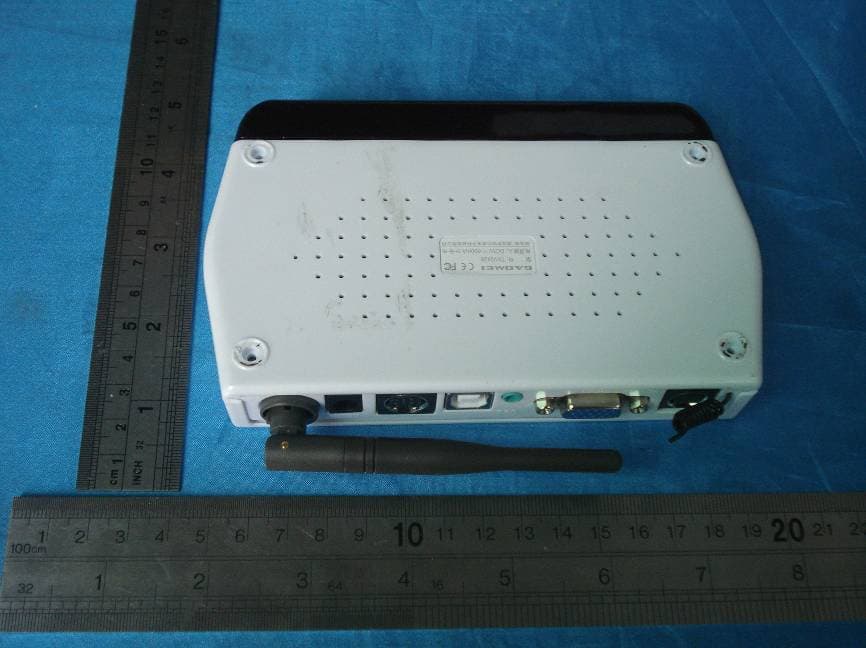
Click to zoom
Application Details
- Equipment Class
- DXX - Part 15 Low Power Communication Device Transmitter
- Date of Grant
- Jan 13, 2008
- Application Purpose
- Original Equipment
- Date of Application
- Jan 13, 2008
- Equipment Note
- WIRELESS PC+A/V TRANSMITTER
- Frequency Range
- 2412.00000000 - 2468.00000000
- Country
- China
Documents & Files
Document Text
Text extracted from the exhibit documents filed with the FCC. Open a document above to read the original.
Users Manual
2.4GHz A/V Receiver 2.4GHz PC+A/V Transmitter VC108VC108 User Manual WIRELESS PC+A/V TRANSMITTER RECEIVER Contents 121 IntroductionPrecautions 1. Introduction 1.1 Brief information VC108 wireless PC+A/V transmitter converts PC signal to video signal with built-in VGA TO VIDEO function. Adapting 2.4GHz wireless technic, it can realize long-range TV receiving. With PS/2 mouse, PC can be long-range operated easily. VC108 is to realize resources sharing through PC TO TV wireless transmission and movie appreciating from PC on TV without space limits. 1.2 Features 1) Wireless transmission function 2.4 GHz ISM frequency band with four optional channels. Support VIDEO TO VIDEO wireless transmission. 433MHz IR remote control re-transmission. 2) VGA TO VIDEO function Built-in VGA TO VIDEO function, convert VGA signal to standard NTSC or PAL video signal ( resizable image and adjustable brightness, contrast, tint, saturation, sharpness). Sensitive to VGA input with resolution up to 1024*768@75Hz. 3) Easy-to-operate Sameband transmitter and receiver pair using (one to multiple or multiple to multiple is available). Play & plug, no software needed. 1.3 Specification 1) TXV2428 Transmitter 4. Precautions 4.1 Normal phenomenon Interruption appears when moving. As adopting RF control technic , there will be momentary interruption in the picture when use remote control. The distance varies according to the surroundings, the ordinary house can reach about 10-20 meters. But if the wall is of iron and concrete, it will largely muffle the signal (may not receive signal or shorten receive distance) 4.2 Use precaution 2.4GHz domestic appliance (such as micro oven ,2.4GHz cordless phone, Bluetooth earphone, 802.11b/g wireless network) may affect the quality of receiving signal even no signal receiving. If affected by micro oven, the receiver can be put far away from it. As for other interruption, you can reset the signal channel of the transmitter and receiver. It is better for transmitting when placing the transmitter to a higher position and the antenna is not sheltered. So is it for the receiver. Power input: supplied by USB(DC 5V 600mA) 2.4GHz channel: 4 channels (2414, 2432, 2450, 2468MHz) Video input: 1Vp-p (PAL/NTSC) Audio input: 1.5Vp-p (L/R) Video output: 1Vp-p (PAL/NTSC) 211 Introduction 2) TRV2402 Receiver Power input: DC 5V 300mA 2.4GHz channel: 4 channels (2414, 2432, 2450, 2468MHz) Mouse type: PS/2 port Video output: 1Vp-p (PAL/NTSC) Audio output: 1.5Vp-p (L/R) 1.4 Resolution 640480 800600 1024768 60/75/85 Hz 60/75/85 Hz 60/75 Hz Resolution Refresh rate 1.5 Application 1.6 Accessories PC TO AV wireless transmission (PC resources sharing) AV TO AV wireless transmissionSTB sharing User manual----------------------------------------------1pcs Power adaptor--------------------------------------------1pcs USB cable------------------------------------------------1pcs AV cable--------------------------------------------------2pcs MMI AV cable-------------------------------------------1pcs Stereo audio cable---------------------------------------1pcs VGA cable-----------------------------------------------1pcs Remote control-------------------------------------------1pcs 1.7 Optional accessory 3) Image adjusting menu Press MENU on the remote control towards IR remote sensor, the following menu will appear: UP and DOWN to select the corresponding item, then press LEFT and RIGHT to reduce or increase corresponding parameter (the parameter will not be memorized after powering off). When the menu is not laid out, UP, DOWN, LEFT and RIGHT is to move the image to up, down, left and right. <HSIZE> <VSIZE> <BRIGHINESS> <CONTRAST> <HUE> <SATURATION> <FLICK> <SHARPNESS> <OSD BACKGROUND> Adjust image width Adjust image height Adjust image brightness Adjust image contrast Adjust image hue Adjust image saturation Adjust image flicking Adjust image sharpness Adjust OSD background color Operation illustration 103 Exterior illustration and installation IR R L VIDEO PS/2 MMI DC-IN 2.4G -ANT VGA-IN VGA-OUT PC-AUDIO USB MMI DC-IN 2.4G -ANT 2. Exterior illustration and installation 1) Transmitter TXV2428 panel and terminal illustration 2.1 Panel and terminal illustration Channel switch Power on/off Source switch VGA output VGA input 433MHz antenna 2.4GHz antenna MMI expansion AV input USB port Audio input(PC) ( Notice: USB connection can provide power supply to TXV2428, no power adaptor needed.) 2) Receiver TRV2402 panel and terminal illustration Channel switch Power on/off Source switch A/V output 433MHz antenna 2.4GHz antenna Power input (DC 5V) Power input (DC 5V) Mouse port 3.2 Remote control operation 1) Panel illustration 2) Function illustration PC/AV: Switch between PC and AV POWER: Enter or exit the standby status CH: Switch the four channels of receiver MENU: Open or close image menu : Select (up) : Select (down) : Select (left) : Select (right) PAL: Switch to PAL system NTSC: Switch to NTSC system Operation illustration 49 IR R L VIDEO PS/2 MMI DC-IN 2.4G -ANT VGA-IN VGA-OUT PC-AUDIO USB MMI DC-IN 2.4G -ANT VGA-IN VGA-OUT PC-AUDIO USB MMI DC-IN 2.4G -ANT 2.2 Connection 1) Transmitter TXV2428 connection PC connection: Notebook connection: Power adaptor AV Monitor Host V G A c a b l e S t e r e o a u d i o c a b l e U S B c a b l e Power adaptor AV USB cable Stereo audio cable VGA cable 2) Receiver TRV2402 connection 3) Channel selection Press channel switch to convert to four 2.4GHz channels. Notice: Only when the receiver and the transmitter in the same channel, can the A/V signal be normally transmitted. Channel selected status indicator as below: If wireless LAN like 802.11(WiFi device) is used in your house, please select channel1 or channel4 and adjust 2.4GHz antenna to avoid its interruption. Notice: Channel4 selected status Channel3 selected status Channel2 selected status Channel1 selected status Exterior illustration and installation Operation illustration 85 Operation illustration (STB/DVD...) 2.3 Product…
Text truncated - open the document above for the full version.
Block Diagram
EM78M611 EXAQ Frequency:12 MHz VX1973 Frequency:27 MHz 4053 2.4GHz Channel IR OUT 433MHz RX 2.4GHz Tx 5V 24C04 KEY LED I2C PC/AV TXV2428 AV R G B 74H C14 HS、VS HS-OUT、 VS-OUT video Video out 5V USB PC Audio
External Photos
DONGGUAN EMTEK CO.,LTD. REPORT NO:E0712714E FCC ID:VHH-TXV2428 DATE:01/04/2008
ID Label/Location Info
Proposed Label Location on EUT Proposed FCC Mark Location
ID Label/Location Info
FCC ID:VHH-TXV2428 This device complies with Part 15 of the FCC Rules. Operation is subject to the following two conditions: 1. This device may not cause harmful interference,and 2. This device must accept any interference received, including interference that may cause undesired operation.
Internal Photos
DONGGUAN EMTEK CO., LTD. REPORT NO:E0712714E FCC ID:VHH-TXV2428 DATE: 01/04/2008 Page 1 of 2 DONGGUAN EMTEK CO., LTD. REPORT NO:E0712714E FCC ID:VHH-TXV2428 DATE: 01/04/2008 Page 2 of 2
Operational Description
Circuit Description This passage is mainly on how TXV2428 wireless A/V transmitter works and is divided into two parts: The first part is on 2.4GHz A/V transmission: There are two kinds of signals input of TXV2428, one is AV signal from VGA signal that is output from PC and encoded by VX1937. The other is AV signal from external signal source. The two kinds of signals are transmitted to 2.4GHz transmitting module to demodulate via CD4053 controlled by MCU EM78M611 and then emitted. (If it is in the same time, you can only select one kind of signal. ) The second part is 433MHz ASK signal receiving: when ASK signal is received by 433MHz receiving module of TXV2428, it will be directly transmitted to MCU EM78M611 to recognize whether it is PS/2 mouse signal or remote control signal from signal source. If it is PS/2 signal, it will be decoded into USB data and transmitted to the mouse controlled by PC. If it is IR remote data, it will be decoded into IR signal and transmitted to IR emitting tube.
Schematics
1 2 3 4 5 6 7 8 9 10 11 12 ABCD 12 11 10 9 8 7 6 5 4 3 2 1 D CBA Title Number Revision Size A1 Date: 6-Dec-2007 Sheet of File: E:\Hard ware\ 无线影音 \VC108\TXV2428\TXV2428_V2.0.ddb Drawn By: AV1 IN +5V 12345678 910111213141516 B1B0C1C OUTC0INHVEEVSS VDD B OUT A OUT A1A0 S0S1S2 U2TC4053 SW_SOURCE AV1_Lin AV1_RinVIDEO_OUTPC_AUDIO_R PC_AUDIO_L PC_VIDEO R6910K R7010K 1 3 2 PJ5PH2 C60105 C41105 R681K R671K PC_AUDIO_L PC_AUDIO_R R2010K R5 10K AV1_Lin AV1_Rin 9 8 7 6 5 1 2 3 4 PJ4 MMI_B 5V1 C2105 C1105 AV1_Vin R264k7 R276K8 R25120R R283K3 PC_VIDEO EC110u/10V AV1_Vin CLKWECASRASA0A1A2A3A4A5A6A7A8A9A10A11 VS A9 DQM A0 D11 A4 D13D15 G-IN A7 A8 CAS D9 A11 A2 A6 A3 D8 A10 A1 D12 WERAS A5 D10D14 CS CLK P/N D4 D4 DQM CS D0 D0 D12D11D5 D5 D6 D6 D2 D2 D7 D7 D1 D1 D3 D3 D14D8D15D10D13D9 CLKDIV HS VGACLKIN 1 EXTVGASEL 2 VGACLKDIV 3 DVSS 4 DVSS 5 A11 6 A10 7 A9 8 A8 9 A7 10 A6 11 A5 12 A4 13 A3 14 A2 15 A1 16 A0 17 DVDD 18 DVDD 19 DVDD 20 AVDDPLL2 21 AVSSPLL2 22 DVSS 23 DVSS 24 XTALO 25 XTALI 26 DVDD 27 EXT81M 28 EXT81MSEL 29 RAM_CLK 30 DVDD 31 DVSS 32 CSB 33 RASB 34 CASB 35 WEB 36 D7 37 D6 38 D5 39 D4 40 D3 41 D2 42 D1 43 D0 44 DVSS 45 DQM 46 DVDD 47 D15 48 D14 49 D13 50 D12 51 D11 52 D10 53 D9 54 D8 55 ADDR_SEL_FREEZE 56 DVSS 57 DVDD 58 SCL 59 SDA 60 CSYNCIN 61 TVSTD2 62 TVSTD1 63 TVSTD0 64 DVDD 65 CVBS1 66 AVSSDAC 67 CVBS2/G/Y 68 AVDDDAC 69 RSET 70 C/B/U 71 AVDDDAC 72 Y/R/V 73 AVSSDAC 74 DVSS 75 DVDD 76 CSYNC 77 TV_VS 78 TV_HS 79 DVSS 80 YUV0_PWRDN 81 YUV1_OSDEN 82 YUV2_ZOOM 83 YUV3_MENU 84 DVDD 85 LLC_SIZE 86 YUV4_LEFT 87 YUV5_RIGHT 88 YUV6_UP 89 YUV7_DOWN 90 HREF_RGB 91 ODD_YUV 92 XRESET 93 DVSS 94 VS 95 HS 96 DVSS 97 BOUT 98 DVDD 99 AVDDADC 100 B 101 AVSSADC 102 AVSSADC 103 AVSSVGC 104 GOUT 105 VRB3 106 AVDDVGC 107 AVDDADC 108 G 109 AVSSADC 110 ROUT 111 AVDDADC 112 R 113 AVSSADC 114 VRB0 116 VTOP0 115 TEST_PAD 117 TAB 118 DVSS 119 GPLLCIN 120 AVSSPLL1 121 MUN5 122 MIVBP2 123 MINTCLK 124 MVCTR 125 R_PAD 126 AVDDPLL1 127 DVDD 128 U12 X427M C98 33P C9933P DQ0 2 DQ1 3 DQ2 5 DQ3 6 DQ4 8 DQ5 9 DQ6 11 DQ7 12 DQ8 39 DQ9 40 DQ10 42 DQ11 43 DQ12 45 DQ13 46 DQ14 48 DQ15 49 A0 21 A1 22 A2 23 A3 24 A4 27 A5 28 A6 29 A7 30 A8 31 A9 32 A10 20 A11 19 RASB 17 CASB 16 WEB 15 CLK 35 LDQM0 36 LDQM1 14 CKE 34 CSB 18 VSSQ0 4 VSSQ1 10 VSSQ2 41 VSSQ3 47 VSS0 26 VSS1 50 CDDQ0 44 CDDQ1 38 CDDQ2 13 CDDQ3 7 VDD0 25 VDD1 1 U13HY57V161610ET-6 C76104 VX1937 1 2 3 4 5 6 7 8 9 10 11 12 13 14 15 J1VGAOUT 1 2 3 4 5 6 7 8 J2S D12BAV99 D13BAV99 D14 BAV99 D15BAV99 D16BAV99 D11BAV99 PC_VS VGA_G PC_HS VGA_R VGA_B R-OUT G-OUT B-OUT VS OUTHS OUT A1 1 B1 2 A2 3 B2 4 A3 5 B3 6 GND 7 B4 8 A4 9 B5 10 A5 11 B6 12 A6 13 VCC 14 U1474HC14 B 2 C 3 E 1 Q171015 C102 104 R11675 R117150 VGA_R R-OUT +5V Q181015 R11875 R119150 VGA_G G-OUT +5V B 2 C 3 E 1 Q191015 R12075 R121150 VGA_B B-OUT +5V +5V PC_HSHS OUT PC_VSVS OUT R1014K7 R1024K7 R98150 HS VS +5V C73 82P C74 82P C75 82P B-INR-IN 3V3A3V3D 3V3A3V3A3V3D3V3A 3V3D 3V3D 3V3D3V3D 3V3D 3V3A 3V3A 3V3D 3V3D R1113K6 R10310K C72104 R110 4K7 R108 4K7 R106 4K7 R107 4K7 R105 4k7 R109 4K7 3V3A 3V3D 3V3D C103 104 C104 104 C101 104 C106 104 C108 104 C105 104 C110 104 C111 104 C112 104 C109 104 C114 104 C115 104 C116 104 C113 104 C118 104 C119 104 C89 104 C117 104 C91 104 C92 104 C93 104 C90 104 C96 104 C95 104 3V3A Q16 1015 R1151M ZD23V9 C65105 5V1 C79270P C80470P L6 1.2U 3V3D 3V3A 3V3D C88 104 C66100P C69104 R99150 C67100P C70104 R100150 C68100P C71104 VGA_RVGA_GVGA_B R-ING-INB-IN R112 75 C82100P C97100P R114150R R113150R D10BAV99 E 1 C 3 B 2 D3BAV99 R104 4K7 PC_VIDEO Q9 C1815 2 2 3 3 1 1 Q8C1815 IR6IR333-A R8310R EC17 220u/16v C28 104 +5V DATA_IR IR_OUT IR2IR333-A +5V 12345678 U10NT-R11A ANTGNDGNDVCCDATAGNDVCCDATA R9147R C29 104 L11 100uH EC13470U/16V PJ2DC EC18100U/16V R624K7 R634K7 IR_ANT2 C30 100P EC10 10u/10V R1710KR614K7 VIDEO_IN 2 2 3 3 1 1 Q5C1815 R481K VIDEO_OUT 5V2 E C B Q4S8550 2 2 3 3 1 1 Q6 C1815 R72680 R731K POWER 5V1 C27104 R8010R C24 20P C2320P 1234 SDA 5 SCL 6 GND 7 VCC 8 24C02 U724C04 DATA_IR TX VIDEO-in 1 GND 2 AUDIO-Rin 3 AUDIO-Lin 4 +5V 5 CH1 7 CH2 8 CH3 9 CH4 10 CH-UP 6 ANT 11 GND 12 E2ZT623TA/TB IR_C +5V 5V1 EC12470U/16V C14 105 EC1110u/10V R711M R3010K R2110K SW4 POWER R4010K SW_SOURCE R4210K R4410K R4510K SW5 SOURCE SW6 CH JK12LED R581K8 JK11LED R571K8 JK5LED R521K8 JK6LED R531K8 JK9LED R541K8 JK10LED R551K8 CH1_LEDCH2_LEDCH3_LEDCH4_LED AV2AV1 L3 100uH VIDEO_IN POWER P/N 5V2 5V2 MENU LEFT RIGHT UP DOWN LEFTRIGHTUPDOWNMENU R12.2K R21K R31K AV_V AV_L AV_R PC_A_L PC_A_R ANT_GND ANT_GND ANT_GND ANT_GND AUDIO-RinAUDIO-Lin R4BEAD P92/SE1 2 P93/SE2/PWM2 3 P94/VPP 4 P95 5 P96 6 VNN 7 P50/AD0 8 P51/AD1 9 P52/AD2 10 P53 11 P54/AD4 12 P55/AD5 13 P56/AD6 14 P57/AD7 15 P80/AD8 16 P81/AD9 17 P82/AD10 18 P83/AD11 19 P84/AD12 20 P85/AD13 21 P86/AD14 22 AD15 23 P60/AD16 24 P61/AD17 25 P62/AD18 26 P63/AD19 27 P64/AD20 28 P65/AD21 29 P66/AD22 30 P67/AD23 31 P72 32 P71 33 P70 34 P77 35 P76 36 VDD 37 OSCI 38 OSCO 39 VSS 40 V3.3 41 D+/CLK/P74 42 D-/DATA/P75 43 P90 44 P91 1 /PWM1/AD3 /P87 U1 EM78M611EXAQ X212MHZ 1234 56 Vcc GND D+ D- GNDGND J3 USB D+D- D- D+ +5V R61K BX 1 CH2 2 CH1 3 CH0 4 VCC 5 GND 6 VIDEO 7 GND 8 AUDIO_L 9 GND 10 AUDIO_R 11 2.4G TX E12.4G TX VIDEO_IN CH1CH2CH3 CH4CH1CH2CH3 5V2 EC2 100U 3V3A C3 104 ZD IN GND OUT U3 AS1117 L1BEAD EC3 220U C4 104 3V3D 5V1 2 2 3 3 1 1 Q7C1815 B 2 C 3 E 1 Q3 1015 R188K2 R198K2 R164K7 R151K ANT_GND ANT_GND ANT_VCC +5V R2210R EC410u/10V VPP DINCK DATAIN /PGM VNN OSCI VDD /OE R13100 123456789 J4 烧写座 VDDGNDOSCIVPPVNN/OE/PGMDATAINDINCK U15 C85 C94 C100104 V3.3 V3.3 EC5 10u/10V GND 1 TRIG 2 OUT 3 RST 4 CVOLT 5 THR 6 DISC 7 VCC 8 U4NE555 R91K5R8100k C6150p C5104 +5V R7 4k7 IR_OUTIR_C
Test Report
DONGGUAN EMTEK CO., LTD. REPORT NO:E0712714E FCC ID:VHH-TXV2428 DATE: 01/12/2008 Page 1 of 20 ELECTROMAGNETIC EMISSIONS COMPLIANCE REPORT INTENTIONAL RADIATOR CERTIFICATION TO FCC PART 15 SUBPART B &C REQUIREMENT OF Wireless PC+A/V Transmitter MODEL No.: TXV2428 Trademark:GADMEI FCC ID: VHH-TXV2428 REPORT NO: E0712714E ISSUE DATE: Jan 12, 2008 Prepared for GADMEI ELECTRONICS TECHNOLOGY CO., LTD. Yin Zhan Farm, Qing Cheng District, Qing Yuan City, Guangdong Province, China Prepared by DONGGUAN EMTEK CO., LTD No.281,Guantai Road,Nancheng District, Dongguan, Guangdong, China TEL: 86-769-22807078 FAX: 86-769-22807079 DONGGUAN EMTEK CO., LTD. REPORT NO:E0712714E FCC ID:VHH-TXV2428 DATE: 01/12/2008 Page 2 of 20 VERIFICATION OF COMPLIANCE Applicant: GADMEI ELECTRONICS TECHNOLOGY CO., LTD. Yin Zhan Farm, Qing Cheng District, Qing Yuan City, Guangdong Province, China Product Description: Wireless PC+A/V Transmitter Trademark: GADMEI Model Number: TXV2428 File Number: E0712714E Date of Test: Dec 26, 2007 to Jan 12, 2008 We hereby certify that: The above equipment was tested by DONGGUAN EMTEK CO., LTD. The test data, data evaluation, test procedures, and equipment configurations shown in this report were made in accordance with the procedures given in ANSI C63.4 (2003) and the energy emitted by the sample EUT tested as described in this report is in compliance with conducted and radiated emission limits of FCC Rules Part 15.249. The test results of this report relate only to the tested sample identified in this report. Approved By Nicol Lee / Q.A. Manager DONGGUAN EMTEK CO., LTD. DONGGUAN EMTEK CO., LTD. REPORT NO:E0712714E FCC ID:VHH-TXV2428 DATE: 01/12/2008 Page 3 of 20 Ta b l e o f C o n t e n t s 1. GENERAL INFORMATION ................................................................................................. 4 1.1 Product Description................................................................................................................................. 4 1.2 Related Submittal(s) / Grant (s)............................................................................................................... 4 1.3 Test Methodology ................................................................................................................................... 4 1.4 Special Accessories ................................................................................................................................. 4 1.5 Equipment Modifications ........................................................................................................................ 4 1.6 Test Facility............................................................................................................................................. 5 2. System Test Configuration......................................................................................................6 2.1 EUT Configuration.................................................................................................................................. 6 2.2 EUT Exercise .......................................................................................................................................... 6 2.3 Test Procedure......................................................................................................................................... 6 2.4 Limitation ................................................................................................................................................ 6 2.5 Configuration of Tested System.............................................................................................................. 8 3. Summary Of Test Results........................................................................................................9 4. Description of test modes......................................................................................................... 9 5. Conducted Emissions Test .................................................................................................... 10 5.1 Measurement Procedure:....................................................................................................................... 10 5.2 Test SET-UP (Block Diagram of Configuration).................................................................................. 10 5.3 Measurement Equipment Used: ............................................................................................................ 10 5.4 Measurement Result:............................................................................................................................. 11 5.5 Conducted Measurement Photos: .......................................................................................................... 12 6. Radiated Emission Test .........................................................................................................13 6.1 Measurement Procedure ........................................................................................................................ 13 6.2 Test SET-UP (Block Diagram of Configuration).................................................................................. 14 6.3 Measurement Equipment Used: ............................................................................................................ 15 6.4 Out of Band Radiated Measurement Result .......................................................................................... 15 6.5 Radiated Measurement Photos: ............................................................................................................. 19 7. Antenna Application ................................................................................................................. 20 7.1 Antenna requirement ............................................................................................................................... 20 7.2 Antenna construction and directional gain .........…
Text truncated - open the document above for the full version.
Test Setup Photos
DONGGUAN EMTEK CO.,LTD. REPORT NO:E0712714E FCC ID:VHH-TXV2428 DATE:01/12/2008 Radiated Emission Setup Photos: Conducted Measurement Photos:
Contact Information
Applicant
Victor Huang(Manager)
Test Firm
EMTEK (DONGGUAN) CO.,LTDSam Lv
Technical Specifications
| # | Rule Parts | Frequency Range | Power Output |
|---|---|---|---|
| 1 | 15C | 2.41 GHz - 2.47 GHz | - |
Other Applications from QINGYUAN GADMEI ELECTRONICS TECHNOLOGY Co., Ltd.

VHH-E8-3DTL803D
May 05, 2013Tablet, Tablet PC, Android Tablet PC
Equipment Class
DSS - Part 15 Spread Spectrum Transmitter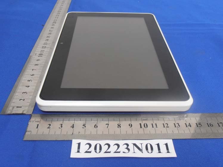
VHH-T860T863E8N8
Mar 27, 2012Tablet
Equipment Class
DTS - Digital Transmission System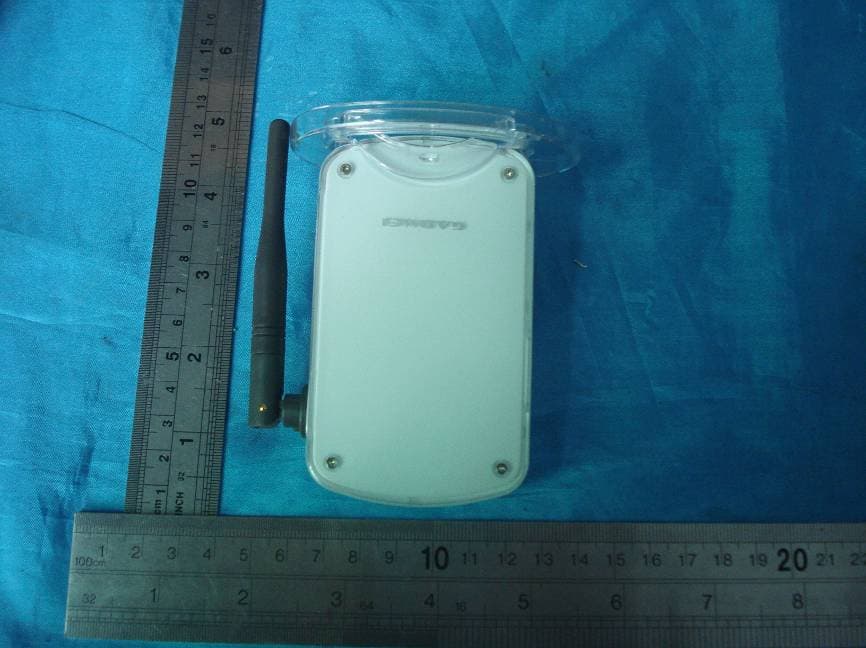
VHH-UTV324
Feb 19, 2008WIRELESS A/V RECEIVER-433 MHZ TX PORTION
Equipment Class
DXX - Part 15 Low Power Communication Device Transmitter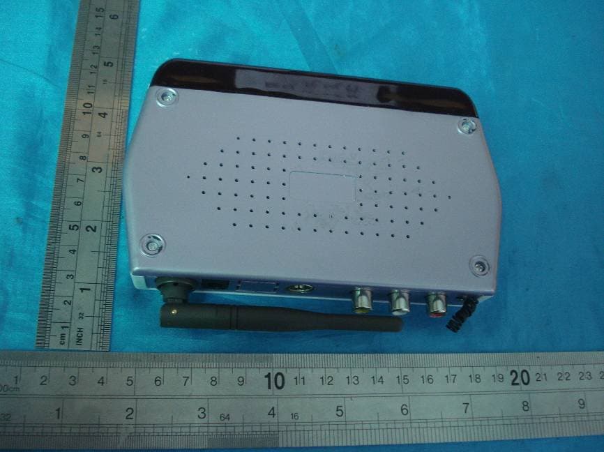
VHH-TXV2408
Jan 13, 2008WIRELESS A/V TRANSMITTER
Equipment Class
DXX - Part 15 Low Power Communication Device Transmitter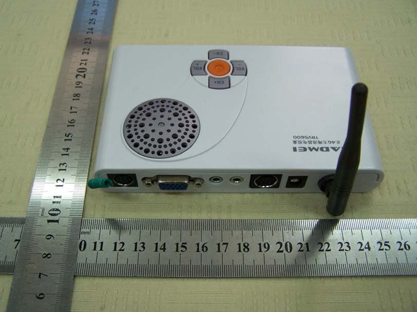
VHH-TV5600
Jul 26, 2007WIRELESS XGA TV BOX
Equipment Class
DXX - Part 15 Low Power Communication Device Transmitter