VHH-UTV324WIRELESS A/V RECEIVER-433 MHZ TX PORTION
QINGYUAN GADMEI ELECTRONICS TECHNOLOGY Co., Ltd.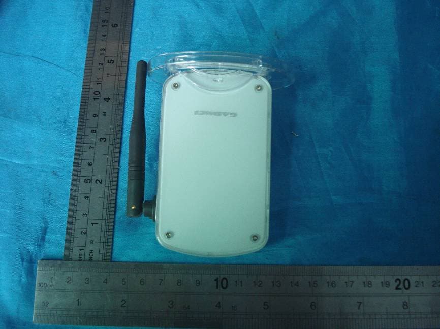
Click to zoom
Application Details
- Equipment Class
- DXX - Part 15 Low Power Communication Device Transmitter
- Date of Grant
- Feb 19, 2008
- Application Purpose
- Original Equipment
- Date of Application
- Feb 19, 2008
- Equipment Note
- WIRELESS A/V RECEIVER-433 MHZ TX PORTION
- Frequency Range
- 433.00000000 - 433.00000000
- Country
- China
Documents & Files
Document Text
Text extracted from the exhibit documents filed with the FCC. Open a document above to read the original.
Users Manual
User’s Manual 240240 2.4GHz Wireless TV Box Contents Contents 27 Precautions 7. Precautions 7.1 Normal phenomenon Interruption appears while moving. Please move to a fixed place to watch. As adopting RF control technic, there will be momentary interruption in the picture when using remote control. The transmission distance varies according to the surroundings; the distance of ordinary house is about 10-20 meters. But if the wall is of iron and concrete, it will largely muffle the signal (can not receive signal or shorten receiving distance) 7.2 Using precautions 2.4GHz domestic appliance (such as micro oven, 2.4GHz cordless phone, Bluetooth earphone, or 802.11b/g wireless network) may affect the quality of receiving even cause no signals receiving. If affected by micro oven, the receiver should be put far from it. As for other interruptions, you can reset the signal channel of the transmitter and receiver. The transmitter should be put on a higher place to get better transmission effect when there is no obstacle around the transmitting antenna, thereby the transmission distance will become longer. It can also reduce the interruption from our moving when the receiver is placed higher. 1 Introduction Combining 2.4GHz wireless technic and USB TV box technic, UTV240 is known as a Hi-Tech product. Advanced 2.4GHz wireless transmission technic effectively realizes CATV or A/V signal wireless transmission in your house. Connected to your laptop or PC via USB cable, you will be satisfied with enjoying your favorite channels and Hi-Fi A/V programs while using computer. Because of high speed USB2.0 port and progressive scanning technic, USB TV presents stable and sharp pictures. Full function remote control makes it easier to watch TV on computer. Attached with multi-function software, you can sequence and rename channels according to your favorite. What's more, some dynamic data can also be recorded on your computer from recorder, video camera, web camera or other video devices and stored onto the hard disc, to burn VCD, SVCD, and DVD disc via special software. With scheduled recording function, you will not miss any highlights. High-quality static picture capturing function converts every highlight into digital album, and you can share with your friends via uploading to the web. 1. Introduction 1.1 Brief introduction 1.2 Features There are 4 channels ,and the frequency scope ranges from 2.400GHz to 2.483GHz. To increase the flexibility and reliability,we prepare four selectable ch- annels (2.414GHZ, 2.432GHz, 2.450GHz, 2.468GHz). Support all frequency TV wireless transmission and VCD , DVD signal transmission. 433MHz IR remote return transmission, easy to operate. IR transmitting, no extension cable needed. Compatible with NTSC/PAL video transmission and stereo audio trans- mission. TV wall function to browse programs easily. Channel list to sequence and rename channels at will. Customizable brightness, contrast, sharpness, hue and saturation. Static picture capturing and real time recording function. Scheduled recording function to catch every highlight. MPEG1/MPEG2 compressed format, convenient for recording disc. Available shortcut key to control your TV like operating computer. 2 1.4 System requirements Operation system: Windows XP (SP2), Vista Pentium2.4G/ Centrino1.4G DirectX 9.0 VGA card or higher version (more than 64MB) Capacity of 512M or higher Hard disc capacity of 1G or higher USB2.0 extension port 1.5 Application TV/AV wireless transmission, connected to laptop and PC. Large-scale conference video system and multimedia teaching. Security system, real time spot wireless monitoring. Introduction 1) 1.3 Specifications TXV2408 wireless A/V transmitter: Power input: DC 5V 300mA Radio-frequency input: 47-870MHz Video input: 1Vp-p (PAL/NTSC) Audio input: 2Vp-p (L/R) 2.4GHz channel: Four channels (2414,2432,2450,2468MHz) UTV324 wireless USB TV box: USB2.0 port Video input: 1Vp-p (PAL/NTSC) Audio input: 1Vp-p (L/R) Audio output: 2Vp-p (L/R) 2.4GHz channel: Four channels (2414,2432,2450,2468MHz) 2) 243 1.6 Common accessories UTV240 user’s manual ---------------------------1pcs Remote control ------------------------------------1pcs Power adapter -------------------------------------1pcs MMI AV cable -------------------------------------1pcs AV cable -------------------------------------------1pcs MINI USB cable& audio cable ------------------1pcs Software disc --------------------------------------1pcs 1.7 Optional accessory MMI S-Video cable(DIN 200S) -----------------1pcs Method two: Use the rear IR transmitting device Put the transmitter in front of the A/V device and make the rear IR remote sensor right towards that of the A/V device. Make sure no obstacles between them. Vertical view Left view (STB/DVD...) (STB/DVD...) Note: If permitted, place like the above for better effects. 6.2 UTV324 placing Follow the connection illustration to connect USB cable and then you can use UTV324. Make sure the IR sensor is right towards the remote control. Introduction Product placing and retransmitting 2.4GHz AV Transmitter 2.4GHz AV Transmitter Power adapter AV output device Sound card Speaker AV output device Laptop 423 L IN E O U T U S B M M I 2 .4 G H z A N T Connection and operation Product placing and retransmitting 2. Connection and operation 2.1 UTV324 connection illustration Note: Refer to Part4 (software instruction) to get UTV324 operation manual. Antenna 2.2 TXV2408 connection illustration and panel operation instruction: Rear panel: Antenna Antenna Rear IR transmitting equipment 1) 2) (STB/DVD...) 6. Product placing and retransmitting 6.1 Transmitter TXV2408 placing CATV watching: When watching CATV, you only need to connect power to CATV signal and place the unit in the proper position. Make sure no obstacle around. A/V devices like DVD, STB watching: Method one: Use the front IR transmitting device Put the transmitter onto the A/V device and make sure IR transmitting sensor is 2-3 cm fo…
Text truncated - open the document above for the full version.
Block Diagram
UTV324 USB 5V 3V3 2V5 POWER Video_out S-Video + AV2(MMI) A V 2.4GHz RX 433MHz TX 2.4GHz Channel SAA7113H Frequency:24.5 76MHz (video) + EMP202 (audio) EM2860 Frequency : 12MHz 4052 LINE OUT USB IRLED EM78P447SAM Frequency:12MHz 4052 24c04 IR
External Photos
DONGGUAN EMTEK CO., LTD. REPORT NO:E0712623E FCC ID:VHH-UTV324 DATE: 01/04/2008 Page 1 of 1
ID Label/Location Info
Proposed Label Location on EUT Proposed FCC Mark Location
ID Label/Location Info
FCC ID:VHH-UTV324 This device complies with Part 15 of the FCC Rules. Operation is subject to the following two conditions: 1. This device may not cause harmful interference,and 2. This device must accept any interference received, including interference that may cause undesired operation.
Internal Photos
DONGGUAN EMTEK CO., LTD. REPORT NO:E0712623E FCC ID:VHH-UTV324 DATE: 01/04/2008 Page 1 of 3 DONGGUAN EMTEK CO., LTD. REPORT NO:E0712623E FCC ID:VHH-UTV324 DATE: 01/04/2008 Page 2 of 3 DONGGUAN EMTEK CO., LTD. REPORT NO:E0712623E FCC ID:VHH-UTV324 DATE: 01/04/2008 Page 3 of 3
Operational Description
Circuit Description This passage is mainly on how UTV324 wireless A/V receiver works and is divided into two parts: The first part is 2.4GHz A/V receiving: 2.4GHz receiving module of UTV324 demodulate 2.4GHz signal into A/V signal and output them to SAA7113 and EMP202, which convert them into digital signals. These digital signals are transmitted to EM2860 and then converted into USB data which is transferred to PC; The digital signal will be displayed via TRV PLUS software. The second part is 433MHz ASK signal transmitting: The remote signal from signal source is converted into digital signal via UTV324 remote receiver. After encoded by MCU EM78P447, the digital signal will be demodulated and emitted via 433MHz transmitting module.
Schematics
DVD.D1 XTL-IN XLX-OUT VDSS1 SDA-OUT BIT-CLK DVSS2 SDA DVD.D2 SYNC SESET PC-BEEP MONO OUTA.VDDHP.OUTHP.COMHP OUT RAVSS 2GP100GP101ID0ID1EAPDSPDIF.OUT LINE.IN-RLINE.IN-L MIC2MIC1CD-R CD GND CD-L TV-R TV-L AUX-R AUX-L PHONE-IN LINE.OUT-R LINE.OUT-L NC NC CAP2 NC AFILT2 AFILT1 VREF.OUT VREF AVSS1 AVDD1 1 2 3 4 5 6 7 8 9 10 11 12 131415161718192021222324 25 26 27 28 29 30 31 32 33 34 35 36 373839404142434445464748 U9 EMP202 1 43 74 402423 5 443132 2627252221201915141312 10 3 42 39 38 36 37 8 18 34 29 33 917 11 2 41 6 16 28 30 35 AI21AI12AI11CESCLSDAAI1DAI2DXTALXTAL1AI22 VSSA0 VSSA1 VSSA2 AGND VSSDE1 VSSD1 VSSDA VSSDE2 VP07VP06VP05VP04VP03VP02VP01VP00RTC0RTS1RTS0AOUTLCC VDDA0 VDDA1 VDDA2 TMS TD1 TDO TCK TRST VDDDE1 VDDDE2 VDDD1 VDDDA U8 SAA7113H R55 33 R56 33 R57 33 R610K R33100R34100 C51 473 C52 473 X1 24.576M C54 22P C6 102 C5522P L7 10uH 1 2 3 4 5 6 7 89 10 11 12 13 14 15 16 Y0 Y2 YOUT Y3 Y1 INH VEE VSS VDD X2 X1 XOUT X0 X3 A B U2 TC4052 R5118 R491K R5018 R47 1K R5356 R5256 R410K R510K C22 104 C23 104 C26 104 C24104 C25 104 D5BAV99 D6BAV99 3 2 1 PJ3 C27 104 C28104 R39 4K7 R38 4K7 R1710K R1810K R19 10K R2010K LED1LED R481K R710K R810K C46105 R46 1M R451M R2612K C48 10 C4910 Y1 12M C34 104 C56270 C57 270 C36 104 L4BEAD C29104 ZD IN GND OUT U5 AS1117-3V3 ZD IN GND OUT U4 AS1117-2V5 C37100U C8104 C9104 C16 104 IR1 R244K7 R32100 5V1 3V3 3V3 2V5 2V5 3V3 3V3 3V3 3V3 3V3 3V3 3V3 3V3 3V3 3V3 3V3 3V3 3V3 3V3 2V5 2V5 2V5 2V5 2V5 2V5 SDA SDA eSDA eSDA SCL SCL eSCL eSCL TV_V TV_V LINE_R LINE_L LINE_RLINE_L LINE_R LINE_L LINE_R LINE_L YIN VIDEOIN CIN 3V3 3V3 V08V09V10V11V12V13 V14 V15 VCLK HREF VREF V15V14V13V12V11V10V09V08 VREFHREFVCLK SDO BCLK SYNC AC97_RST SDOSYNCRNBCLK TV_L UTV 324.SCH 5V1 TV_AUDIO TV_AUDIO 24M 24M 24M 24M R54 33 D4BAV99 D3BAV99 12345678910111213141516 17 18 19 20 21 22 23 24 25 26 27 28 29 30 31 32 33343536373839404142434445464748 49 50 51 52 53 54 55 56 57 58 59 60 61 62 63 64 NCNCNCNCAVCC3AGNDNCDGNDVID(0)VCC2VID(1)VID(2)VID(3)DGNDVID(4)VID(5) VID(6) VCC3 VID(7) VCLK XCLK HREF VREF SCL SDA DGND PI00 PI01 PI02 PI03 SDI VCC3 IR BCLKSYNC SD0 PIO4 DGND PIO5GNDPIO6 VCC2 PIO7 FID RN SANPLED PW_DOW DP DM RREF AGND VCC3 XSCO XSC1 DGND VCC2 UCLKI CLKINT VCC3 ESTPHY TEST WSEL DGND U7EM2860 GPIO0 GPIO1 GPIO2 GPIO3 REM REM 1 2 3 45 6 7 8 GND GND GND GNDGND 5V1 SCL SDA U324C04 5V1 eSCLeSDA L3 15uH C30 104 C31 104 C32 104 C35104 eSCLeSDA PW_DOW C410u C43105 1 2 3 4 5 6 7 89 10 11 12 13 14 15 16 Y0 Y2 YOUT Y3 Y1 INH VEE VSS VDD X2 X1 XOUT X0 X3 A B U1 TC4052 eSCL eSDAPW_DOWSDA SCL R374K7 R364K7 eSCL C3 10u SCLSDAPW_DOWESDA 1 2 3 4 5 6 PJ2 C10104 C11104 C18104 C19104 C20104 C21104 OUT_R OUT_L OUT_L OUT_R D1 BAV99 D2BAV99 5V1 OUT_L OUT_R C58104 C59104 R5810K R211K R31M C2 105 Q2 A1015 PW_DOW 3V3 R21K AC97_RST L1 100uH EC9 220u/16V TV_LTV_R 5V1 CH1CH2CH3 123456789 10 111213 BXCH3CH2CH1GNDVCCAUDIO_L AUDIO_R VIDEOGND GNDGNDGNDGNDGND ANT RX1 16PIN TV_R DATA_IR 1 2 3 4 5 U6NT-T03A ANT GND GND VCC DATA R110R 0805 C5100P C1 104 EC3100U/16V IR_ANT1 TV_V C14105 12 X212MHZ C1215PC715P TCC 3 VDD 4 NC 5 VSS 6 /INT 7 SOURCE 8 KEY0 9 KEY1 10 KEY2 11 LED0 12 LED1 13 LED2 14 P63 15 RE_IN/OUT 16 P65 17 P66 18 DATA_IR 19 P70 20 SYS_VGA 21 CH1 22 CH2 23 CH3 24 CH4 25 SDA_EEP 26 SCL_EEP 27 OSCO 28 OSCI 29 /RESET 30 P55 1 P54 2 P56 32 P57 31 U10 EM78P447SAM R91M R1110K R10 10K R1510K R22 10K D71N4148 C13 105 R1610 REM CH1 CH2 CH3 DATA_IR R1410K R1210K R1310K SDASCL R23 4K7 5V1 5V1 R27 18R R2556R C17104 9 6 5 2 4 1 8 3 7 10 U11MMI-C C33 22uF C15105 P63 P63 R284K7 5V1 C39 104 C38104 R29 NC R30 NC
Test Report
DONGGUAN EMTEK CO., LTD. REPORT NO:E0712623E FCC ID:VHH-UTV324 DATE: 02/13/2008 Page 1 of 24 ELECTROMAGNETIC EMISSIONS COMPLIANCE REPORT INTENTIONAL RADIATOR CERTIFICATION TO FCC PART 15 SUBPART B &C REQUIREMENT OF Wireless A/V Receiver MODEL No.: UTV324 Tr a d e m a r k : G A D M E I FCC ID: VHH-UTV324 REPORT NO: E0712623E ISSUE DATE: Feb 13, 2008 Prepared for GADMEI ELECTRONICS TECHNOLOGY CO., LTD. Yin Zhan Farm, Qing Cheng District, Qing Yuan City, Guangdong Province, China Prepared by DONGGUAN EMTEK CO., LTD No.281,Guantai Road,Nancheng District, Dongguan, Guangdong, China TEL: 86-769-22807078 FAX: 86-769-22807079 DONGGUAN EMTEK CO., LTD. REPORT NO:E0712623E FCC ID:VHH-UTV324 DATE: 02/13/2008 Page 2 of 24 VERIFICATION OF COMPLIANCE Applicant: GADMEI ELECTRONICS TECHNOLOGY CO., LTD. Yin Zhan Farm, Qing Cheng District, Qing Yuan City, Guangdong Province, China Product Description: Wireless A/V Receiver Trademark: GADMEI Model Number: UTV324 File Number: E0712623E Date of Test: Dec 23, 2007 to Feb 12, 2008 We hereby certify that: The above equipment was tested by DONGGUAN EMTEK CO., LTD. The test data, data evaluation, test procedures, and equipment configurations shown in this report were made in accordance with the procedures given in ANSI C63.4 (2003) and the energy emitted by the sample EUT tested as described in this report is in compliance with conducted and radiated emission limits of FCC Rules Part 15.231. The test results of this report relate only to the tested sample identified in this report. Approved By Nicol Lee / Q.A. Manager DONGGUAN EMTEK CO., LTD. DONGGUAN EMTEK CO., LTD. REPORT NO:E0712623E FCC ID:VHH-UTV324 DATE: 02/13/2008 Page 3 of 24 Ta b l e o f C o n t e n t s 1. GENERAL INFORMATION ................................................................................................. 5 1.1 Product Description................................................................................................................................. 5 1.2 Related Submittal(s) / Grant (s)............................................................................................................... 5 1.3 Test Methodology ................................................................................................................................... 5 1.4 Special Accessories ................................................................................................................................. 5 1.5 Equipment Modifications ........................................................................................................................ 5 1.6 Test Facility............................................................................................................................................. 6 2. System Test Configuration......................................................................................................7 2.1 EUT Configuration.................................................................................................................................. 7 2.2 EUT Exercise .......................................................................................................................................... 7 2.3 Test Procedure......................................................................................................................................... 7 2.4 Limitation ................................................................................................................................................ 7 2.5 Configuration of Tested System.............................................................................................................. 9 3. Summary Of Test Results...................................................................................................... 10 4. Description of test modes.......................................................................................................10 5. Conducted Emissions Test .................................................................................................... 11 5.1 Measurement Procedure:....................................................................................................................... 11 5.2 Test SET-UP (Block Diagram of Configuration).................................................................................. 11 5.3 Measurement Equipment Used: ............................................................................................................ 11 5.4 Measurement Result:............................................................................................................................. 12 5.5 Conducted Measurement Photos: .......................................................................................................... 13 6. Radiated Emission Test .........................................................................................................14 6.1 Measurement Procedure ........................................................................................................................ 14 6.2 Test SET-UP (Block Diagram of Configuration).................................................................................. 15 6.3 Measurement Equipment Used: ............................................................................................................ 16 6.4 Out of Band Radiated Measurement Result .......................................................................................... 16 6.5 Radiated Measurement Photos: ............................................................................................................. 19 7. ACTIVATION TESTING ..................................................................................................... 20 7.1 Requirement .......................................................................................................................................... 20 7.2 Test SET-UP .......................................................…
Text truncated - open the document above for the full version.
Test Setup Photos
DONGGUAN EMTEK CO.,LTD. REPORT NO:E0712623E FCC ID:VHH-UTV324 DATE:02/13/2008 Radiated Emission Setup Photos: Conducted Measurement Photos:
Contact Information
Applicant
Victor Huang(Manager)
Test Firm
EMTEK (DONGGUAN) CO.,LTDSam Lv
Technical Specifications
| # | Rule Parts | Frequency Range | Power Output |
|---|---|---|---|
| 1 | 15C | 433 MHz - 433 MHz | - |
Other Applications from QINGYUAN GADMEI ELECTRONICS TECHNOLOGY Co., Ltd.

VHH-E8-3DTL803D
May 05, 2013Tablet, Tablet PC, Android Tablet PC
Equipment Class
DSS - Part 15 Spread Spectrum Transmitter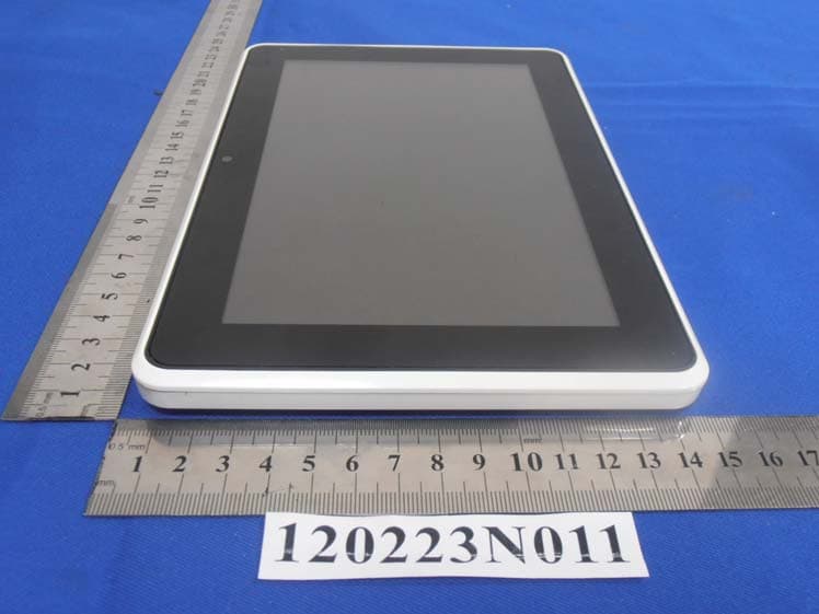
VHH-T860T863E8N8
Mar 27, 2012Tablet
Equipment Class
DTS - Digital Transmission System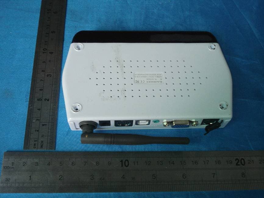
VHH-TXV2428
Jan 13, 2008WIRELESS PC+A/V TRANSMITTER
Equipment Class
DXX - Part 15 Low Power Communication Device Transmitter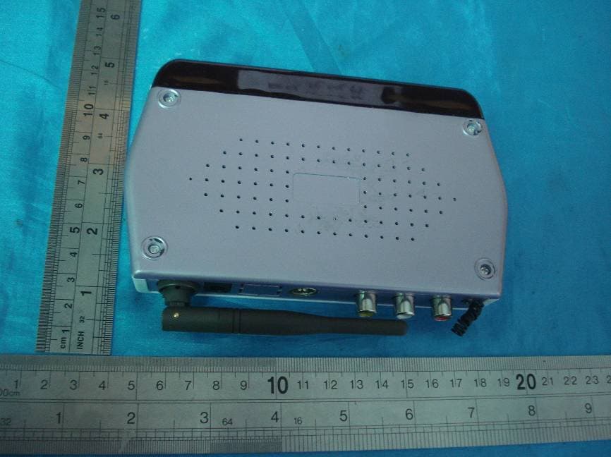
VHH-TXV2408
Jan 13, 2008WIRELESS A/V TRANSMITTER
Equipment Class
DXX - Part 15 Low Power Communication Device Transmitter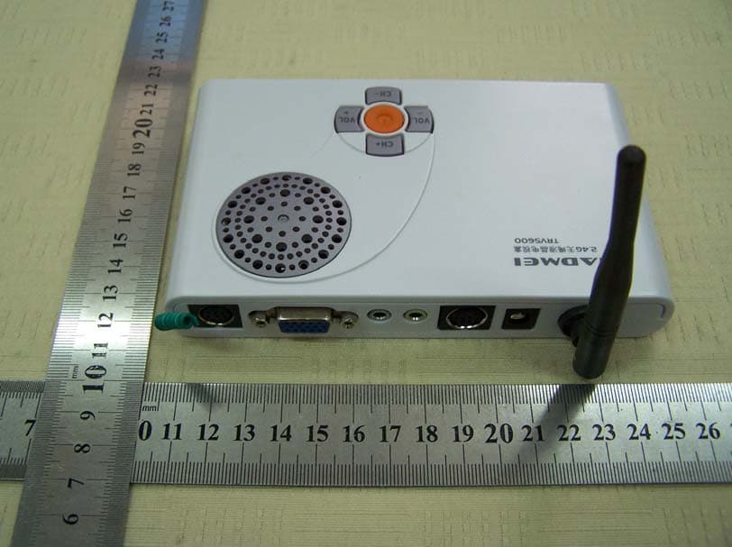
VHH-TV5600
Jul 26, 2007WIRELESS XGA TV BOX
Equipment Class
DXX - Part 15 Low Power Communication Device Transmitter