VJS-MA5000Wireless AirPlay Speaker with 802.11b/g
Altec Lansing, LLC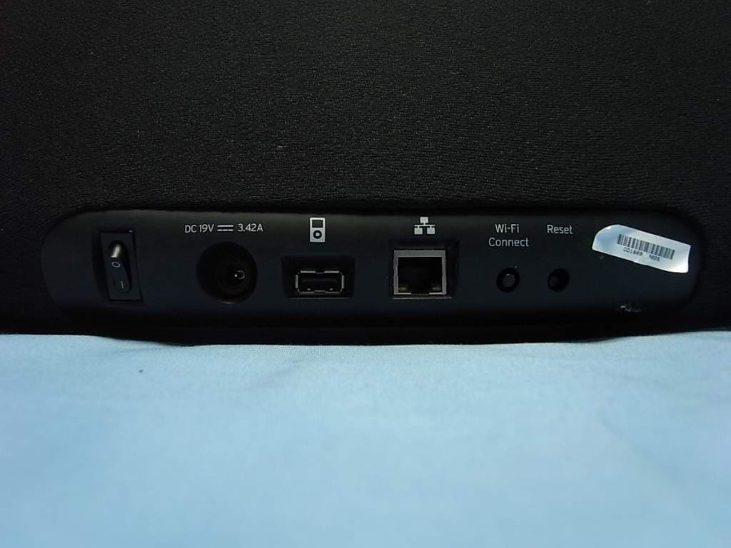
Click to zoom
Application Details
- Equipment Class
- DTS - Digital Transmission System
- Date of Grant
- Oct 25, 2011
- Application Purpose
- Original Equipment
- Date of Application
- Oct 24, 2011
- Equipment Note
- Wireless AirPlay Speaker with 802.11b/g
- Frequency Range
- 2412.00000000 - 2462.00000000
- Company
- Altec Lansing, LLC
- Country
- United States
Documents & Files
Document Text
Text extracted from the exhibit documents filed with the FCC. Open a document above to read the original.
Users Manual
inAir™ 5000 QUICK CONNECT GUIDE Model: MA5000 Recommended Setup 1 Before we begin You should have a Wi-Fi network in your home. A current iOS device (iPad, iPhone, or iPod toch) with iOS 4.2 or later. Make sure your iTunes is running the latest version 10.1 (Mac and PC). Download the inAir Guide application for your iOS device. Have your Wi-Fi network name and password ready for reference. The contents in your box should be accessible and ready to go. iPhone®, iPod®, iPad® and iTunes® are trademarks of Apple Inc., registered in the U.S. and other countries. Wi-Fi is a registered trademark of the Wi-Fi Alliance. Recommended Setup 2 Connect your devices Attach your iOS device to the inAir 5000 with your USB cable. Connect your device to power with the supplied AC adapter. Power On your device. Recommended Setup 3 Launch the app The app will auto-launch or you will be prompted to download. Follow the inAir Guide application to setup your device. Recommended Setup 4 Start playing music You can now enjoy beautiful, crisp, and powerful sound by sending music from your iOS device or PC/Mac computer to your inAir 5000. Conveniently control your inAir 5000 with the supplied remote control. For additional information, please visit: http://www.alteclansing.com 5 LED Indicator Chart Color Meaning Flashing Blue Blue Connecting On / Connected Wi-Fi Setup Configure Mode Firmware Update Available Firmware Error Flashing Orange Flashing Green Flashing White Flashing Red 6 Troubleshooting TBD: Based on user feedback from Beta testing. inAir™ 5000 QUICK CONNECT GUIDE Model: MA5000 Wi-Fi Setup 1 Before we begin You should have a Wi-Fi network in your home. A current iOS device (iPad, iPhone, or iPod toch) with iOS 4.2 or later. Make sure your iTunes is running the latest version 10.1 (Mac and PC). Download the Altec Lansing Quick Connect App for your iOS device. Have your Wi-Fi network name and password ready for reference. The contents in your box should be accessible and ready to go. iPhone®, iPod®, iPad® and iTunes® are trademarks of Apple Inc., registered in the U.S. and other countries. Wi-Fi is a registered trademark of the Wi-Fi Alliance. Wi-Fi Setup 2 Connect to Wi-Fi Disconnect any ethernet or power cables. Then connect the power cable and power On your inAir 5000. Wait for LED to start flashing orange. This will take approximately 40 seconds. Flashing Orange Wi-Fi Setup 3 Select Altec Setup Network From your iOS device or PC/Mac computer, enter your Wi-Fi Settings and select the Altec Setup Network. Wait for the LED to start flashing green. This will indicate that you have entered the Altec Setup Network. Flashing Green Wi-Fi Setup 4 Launch your browser Launch your web browser from your preferred device and enter http://169.254.1.1 into the adress bar. Wi-Fi Setup 5 Name and Join Enter a name for your device and press the button Apply. Choose your home network and enter passkey. Press the button Join Networks Wi-Fi Setup 5 Rejoin your Wi-Fi network Enter your Settings and choose your home network. This will disconnect the temporary Altec Setup Network. Your device LED should display as solid blue. You are now ready to play music from your iOS device or PC/Mac to your inAir 5000! Wi-Fi Setup Blue
Users Manual
inAir™ 5000 Saftey and Warranty Model: MA5000 12 p Note: The manufacturer is not responsible for any radio or TV interference caused by unauthorized modifications to this equipment. Such modifications could void the user’s authority to operate the equipment. www.alteclansing.com Regulation Information ALTEC LANSING ONE-YEAR LIMITED WARRANTY What Does the Warranty Cover? Altec Lansing warrants that its products shall be free from defects in materials or workmanship, with the exceptions stated below. What Is the Period of Coverage? This warranty runs for one year from the date of purchase. The term of any warranties implied by law shall expire when your limited warranty expires. Some states and/or Member States in the European Union do not allow limitations on how long an implied warranty lasts, so the above limitation may not apply to you. What Does the Warranty Not Cover? This warranty does not cover any defect, malfunction or failure that occurs as a result of: improper installation; misuse or failure to follow the product directions; abuse; or use with improper, unintended or faulty equipment. (For information on proper installation, operation and use consult the manual supplied with the product. If you require a replacement manual, you may download a manual from www.alteclansing.com.) Also, consequential and incidental damages are not recoverable under this warranty. Some states do not allow the exclusion or limitation of incidental or consequential damages, so the above limitation or exclusion may not apply to you. What Will Altec Lansing Do to Correct the Problem? Altec Lansing will, at its option, repair or replace any product that proves to be defective in material or workman- ship. If your product is no longer being manufactured, or is out of stock, at its option, Altec Lansing may replace your product with a similar or better Altec Lansing product. How to Get Warranty Service To get a covered product repaired or replaced, you must contact Altec Lansing during the warranty period by email ([email protected]). You must include in your email, your name, address, email address, telephone number, date of purchase and a complete description of the problem you are experiencing. In the United States, you may alternatively contact Altec Lansing by telephone at 1-800-ALTEC88 – please be prepared to provide the same information. If the problem appears to be related to a defect in material or workmanship, upon proof of purchase Altec Lansing will provide you a return authorization and instructions for return shipment. Return shipments shall be at the customer’s expense. You should insure the shipment as appropriate because you are responsible for the product until it arrives at Altec Lansing. Warranty How Will State Law Affect Your Rights? This warranty gives you specific legal rights, and you may also have other rights which vary from state to state. Please note that in the European Union, you as a consumer might have other legal rights under national legislation of European Union Member States governing the sale of Altec Lansing’s goods. Those rights are not affected by this guarantee. The above limited warranties and remedies are sole warranties and remedies available to purchaser, if, and to the extent, valid and enforceable under the applicable law. www.alteclansing.com Warranty To get a covered product repaired or replaced, you must contact Altec Lansing during the warranty period by email ([email protected]). You must include in your email, your name, address, email address, telephone number, date of purchase and a complete description of the problem you are experiencing. In the United States, you may alternatively contact Altec Lansing by telephone at 1-800-ALTEC88 – please be prepared to provide the same information. If the problem appears to be related to a defect in material or workmanship, upon proof of purchase Altec Lansing will provide you a return authorization and instructions for return shipment. Return shipments shall be at the customer’s expense. You should insure the shipment as appropriate because you are responsible for the product until it arrives at Altec Lansing. Warranty How Will State Law Affect Your Rights? This warranty gives you specific legal rights, and you may also have other rights which vary from state to state. Please note that in the European Union, you as a consumer might have other legal rights under national legislation of European Union Member States governing the sale of Altec Lansing’s goods. Those rights are not affected by this guarantee. The above limited warranties and remedies are sole warranties and remedies available to purchaser, if, and to the extent, valid and enforceable under the applicable law. This symbol on the product or on its packaging indicates that this product shall not be treated as household waste. Instead it shall be handed over to the applicable collection point for the recycling of electrical and electronic equipment. By ensuring this product is disposed of correctly, you will help prevent potential negative consequences for the environment and human health, which could otherwise be caused by inappropriate waste handling of this product. The recycling of materials will help to conserve natural resources. For more detailed information about recycling of this product, please contact your local city office or your household waste disposal service. www.alteclansing.com Warranty Service Disposal of Old Electrial and Electronic Equipment
External Photos
FIGURE 1 WIRELESS AIRPLAY SPEAKER (M/N: MA5000) GENERAL APPEARANCE (FRONT VIEW) F IGURE 2 WIRELESS AIRPLAY SPEAKER (M/N: MA5000) GENERAL APPEARANCE (BACK VIEW) FIGURE 3 WIRELESS AIRPLAY SPEAKER (M/N: MA5000) GENERAL APPEARANCE (BOTTOM VIEW) F IGURE 4 WIRELESS AIRPLAY SPEAKER (M/N: MA5000) L ABEL FIGURE 5 WIRELESS AIRPLAY SPEAKER (M/N: MA5000) SIDE PORTS F IGURE 6 WIRELESS AIRPLAY SPEAKER (M/N: MA5000) BACK PORTS FIGURE 7 WIRELESS AIRPLAY SPEAKER (M/N: MA5000) LAN CABLE
ID Label/Location Info
Label Location Information Refer to the below red arrow: (For example)
Internal Photos
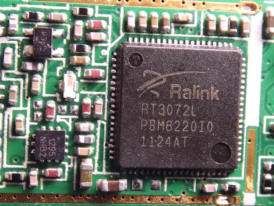
FIGURE 1 WIRELESS AIRPLAY SPEAKER (M/N: MA5000) COVER REMOVED #1 F IGURE 2 WIRELESS AIRPLAY SPEAKER (M/N: MA5000) COVER REMOVED #2 FIGURE 3 WIRELESS AIRPLAY SPEAKER (M/N: MA5000) MAIN BOARD (GENERAL APPEARANCE) FIGURE 4 WIRELESS AIRPLAY SPEAKER (M/N: MA5000) MAIN BOARD (COMPONENT SIDE) F IGURE 5 WIRELESS AIRPLAY SPEAKER (M/N: MA5000) MAIN BOARD (SOLDERED SIDE) FIGURE 6 WIRELESS AIRPLAY SPEAKER (M/N: MA5000) RF BOARD (COMPONENT SIDE) F IGURE 7 WIRELESS AIRPLAY SPEAKER (M/N: MA5000) RF BOARD (SHIELDED COVER REMOVED #1) FIGURE 8 WIRELESS AIRPLAY SPEAKER (M/N: MA5000) RF BOARD (SHIELDED COVER REMOVED #2) F IGURE 9 WIRELESS AIRPLAY SPEAKER (M/N: MA5000) RF BOARD (SOLDERED SIDE) FIGURE 10 WIRELESS AIRPLAY SPEAKER (M/N: MA5000) A NTENNA BOARD FIGURE 11 WIRELESS AIRPLAY SPEAKER (M/N: MA5000) BUTTON BOARD #1 (COMPONENT SIDE) F IGURE 12 WIRELESS AIRPLAY SPEAKER (M/N: MA5000) BUTTON BOARD #1 (SOLDERED SIDE) FIGURE 13 WIRELESS AIRPLAY SPEAKER (M/N: MA5000) BUTTON BOARD #2 (COMPONENT SIDE) F IGURE 14 WIRELESS AIRPLAY SPEAKER (M/N: MA5000) BUTTON BOARD #2 (SOLDERED SIDE) FIGURE 15 WIRELESS AIRPLAY SPEAKER (M/N: MA5000) ADAPTER (GENERAL APPEARANCE) F IGURE 16 WIRELESS AIRPLAY SPEAKER (M/N: MA5000) ADAPTER (AC PORT) FIGURE 17 WIRELESS AIRPLAY SPEAKER (M/N: MA5000) ADAPTER (LABEL) FIGURE 18 WIRELESS AIRPLAY SPEAKER (M/N: MA5000) CONTROLLER (GENERAL APPEARANCE – FRONT VIEW) F IGURE 19 WIRELESS AIRPLAY SPEAKER (M/N: MA5000) CONTROLLER (GENERAL APPEARANCE – BACK VIEW) FIGURE 20 WIRELESS AIRPLAY SPEAKER (M/N: MA5000) CONTROLLER (COVER REMOVED) F IGURE 21 WIRELESS AIRPLAY SPEAKER (M/N: MA5000) CONTROLLER (BOARD – COMPONENT SIDE) F IGURE 22 WIRELESS AIRPLAY SPEAKER (M/N: MA5000) C ONTROLLER (BOARD – SOLDERED SIDE)
RF Exposure Info
Altec Lansing, LLC FCC ID: VJS-MA5000 Page 1 of 7 Audix Technology (Shanghai) Co., Ltd. Report No.: ACI-F11130 Prepared For : Altec Lansing, LLC 9330 Scranton Road, Suite 600, San Diego, CA 92121, USA Prepared By : Audix Technology (Shanghai) Co., Ltd. 3F 34Bldg 680 Guiping Rd., Caohejing Hi-Tech Park, Shanghai 200233, China Tel: +86-21-64955500 Fax: +86-21-64955491 Report No. : ACI-F11130 Date of Test : Sep. 05, 2011 Date of Report : Sep. 21, 2011 Application for FCC Certification On behalf of Altec Lansing, LLC Product Name: Wireless AirPlay Speaker Model No.: MA5000 Serial No.: DD1809M00033 FCC ID: VJS-MA5000 (MPE Calculation) Altec Lansing, LLC FCC ID: VJS-MA5000 Page 2 of 7 Audix Technology (Shanghai) Co., Ltd. Report No.: ACI-F11130 TABLE OF CONTENTS Page 1 GENERAL INFORMATION .......................................................................................................... 4 1.1 Description of Equipment Under Test ........................................................................................ 4 1.2 Description of Test Facility ........................................................................................................ 5 1.3 Measurement Uncertainty .......................................................................................................... 5 2 SUMMARY OF STANDARDS AND RESULTS .......................................................................... 6 2.1 Applicable Standard ................................................................................................................... 6 2.2 Specification Limits ................................................................................................................... 6 2.3 MPE Calculation Method ........................................................................................................... 6 2.4 Calculated Result ........................................................................................................................ 7 Altec Lansing, LLC FCC ID: VJS-MA5000 Page 3 of 7 Audix Technology (Shanghai) Co., Ltd. Report No.: ACI-F11130 TEST REPORT FOR FCC CERTIFICATE Applicant : Altec Lansing, LLC Manufacturer : Inventec Appliances (Pudong) Corporation EUT Description : Wireless AirPlay Speaker (A) Model No. : MA5000 (B) Serial No. : DD1809M00033 (C) Test Voltage : AC 120V/60Hz Test Procedure Used: FCC OET Bulletin 65 August 1997 The device described above is tested by Audix Technology (Shanghai) Co., Ltd. to determine the maximum emission levels emanating from the device. The maximum emission levels are compared to the FCC OET Bulletin 65. The test results are contained in this test report and Audix Technology (Shanghai) Co., Ltd. is assumed full responsibility for the accuracy and completeness of these measurements. This report also shows that the EUT (M/N: MA5000, S/N: DD1809M00033), which was tested on Sep. 05, 2011 is technically compliance with the FCC limits. This report applies to above tested sample only. This report shall not be reproduced in part without written approval of Audix Technology (Shanghai) Co., Ltd. This report must not be used by the client to claim product certification, approval, or endorsement by NVLAP, NIST, or any agency of the federal government. Date of Test : Sep. 05, 2011 Date of Report : Sep. 21, 2011 Producer : KATHY WANG / Assistant Review : DIO YANG / Assistant Manager Signatory : BYRON KWO/ Senior Manager Altec Lansing, LLC FCC ID: VJS-MA5000 Page 4 of 7 Audix Technology (Shanghai) Co., Ltd. Report No.: ACI-F11130 1 GENERAL INFORMATION 1.1 Description of Equipment Under Test Description : Wireless AirPlay Speaker Type of EUT ; Production Pre-product Pro-type Model Number : MA5000 Serial Number : DD1809M00033 Radio Tech : IEEE 802.11b/g Freq. Band : 2412 MHz - 2462 MHz Total 11 Channels in 5 MHz Separation Tested Freq. : 2412 MHz (Channel 01) 2437 MHz (Channel 06) 2462 MHz (Channel 11) Modulation : DSSS for 802.11b OFDM for 802.11g Transmit data rate: 802.11b: 1, 2, 5.5, 11, 22 Mbps 802.11g: 6, 9, 12, 18, 24, 36, 48, 54 Mbps After testing, the highest average output power of the EUT was at 1 Mbps in 802.11b mode and 12 Mbps in 802.11g mode. So 1 Mbps and 12 Mbps mode were representative selected to test in this report. Antenna Gain : 4.59 dBi Applicant : Altec Lansing, LLC 9330 Scranton Road, Suite 600, San Diego, CA 92121, USA Manufacturer : Inventec Appliances (Pudong) Corporation No. 789 Pu Xing Road, Shanghai, PRC Altec Lansing, LLC FCC ID: VJS-MA5000 Page 5 of 7 Audix Technology (Shanghai) Co., Ltd. Report No.: ACI-F11130 1.2 Description of Test Facility Site Description : Sept. 17, 1998 file on (Semi-Anechoic Chamber) Apr 29, 2009 Renewed Federal Communications Commission FCC Engineering Laboratory 7435 Oakland Mills Road Columbia, MD 21046, USA Name of Firm : Audix Technology (Shanghai) Co., Ltd. Site Location : 3 F 34 Bldg 680 Guiping Rd., Caohejing Hi-Tech Park, Shanghai 200233, China FCC registration Number : 91789 Accredited by NVLAP, Lab Code : 200371-0 1.3 Measurement Uncertainty Output Power Expanded Uncertainty : U = 0.30 dB Altec Lansing, LLC FCC ID: VJS-MA5000 Page 6 of 7 Audix Technology (Shanghai) Co., Ltd. Report No.: ACI-F11130 2 SUMMARY OF STANDARDS AND RESULTS 2.1 Applicable Standard FCC OET Bulletin 65:1997 2.2 Specification Limits Limits for General Population/Uncontrolled Exposure Frequency Range (MHz) Electric Field Strength (E) (V/m) Magnetic Field Strength (H) (A/m) Power Density (S) (mW/cm 2 ) Averaging Time |E| 2 , |H| 2 or S (minutes) 0.3-1.34 614 1.63 (100)* 30 1.34-30 824/f 2.19/f (180/f2)* 30 30-300 27.5 0.073 0.2 30 300-1500 -- -- f/150 30 1500-100,000 -- -- 1.0 30 f = frequency in MHz *Plane-wave equivalent power density NOTE: General population/uncontrolled exposures apply in situations in which the general public may be exposed, or in which persons that are exposed as a consequence of their employment may not be fully aware of the potential for exposure or can not exercise control…
Text truncated - open the document above for the full version.
Test Report
Altec Lansing, LLC FCC ID: VJS-MA5000 Page 1 of 57 Audix Technology (Shanghai) Co., Ltd. Report No.: ACI-F11129 Prepared For : Altec Lansing, LLC 9330 Scranton Road, Suite 600, San Diego, CA 92121, USA Prepared By :Audix Technology (Shanghai) Co., Ltd. 3F 34Bldg 680 Guiping Rd., Caohejing Hi-Tech Park, Shanghai 200233, China Tel: +86-21-64955500 Fax: +86-21-64955491 Report No. : ACI-F11129 Date of Test : Sep. 05 - 09, 2011 Date of Report : Sep. 20, 2011 Application for FCC Certification On behalf of Altec Lansing, LLC Product Name: Wireless AirPlay Speaker Model No.: MA5000 Serial No.: DD1809M00033 FCC ID: VJS-MA5000 Altec Lansing, LLC FCC ID: VJS-MA5000 Page 2 of 57 Audix Technology (Shanghai) Co., Ltd. Report No.: ACI-F11129 TABLE OF CONTENTS Page 1 SUMMARY OF STANDARDS AND RESULTS .......................................................................... 5 1.1 Description of Standards and Results ......................................................................................... 5 2 GENERAL INFORMATION .......................................................................................................... 6 2.1 Description of Equipment Under Test ........................................................................................ 6 2.2 Description of Test Facility ........................................................................................................ 7 2.3 Measurement Uncertainty .......................................................................................................... 7 3 CONDUCTED EMISSION TEST .................................................................................................. 8 3.1 Test Equipment ........................................................................................................................... 8 3.2 Block Diagram of Test Setup ..................................................................................................... 8 3.3 Conducted Emission Limits [FCC Part 15 Subpart C 15.207] ................................................... 8 3.4 Test Configuration ...................................................................................................................... 8 3.5 Operating Condition of EUT ...................................................................................................... 9 3.6 Test Procedures .......................................................................................................................... 9 3.7 Test Results ................................................................................................................................ 9 4 RADIATED EMISSION TEST ..................................................................................................... 11 4.1 Test Equipment ......................................................................................................................... 11 4.2 Block Diagram of Test Setup ................................................................................................... 11 4.3 Radiated Emission Limit [FCC Part 15 Subpart C 15.209] ..................................................... 12 4.4 Test Configuration .................................................................................................................... 12 4.5 Operating Condition of EUT .................................................................................................... 12 4.6 Test Procedures ........................................................................................................................ 12 4.7 Test Results .............................................................................................................................. 14 5 6 dB BANDWIDTH MEASUREMENT ....................................................................................... 38 5.1 Test Equipment ......................................................................................................................... 38 5.2 Block Diagram of Test Setup ................................................................................................... 38 5.3 Specification Limits (§15.247(a)(2)) ........................................................................................ 38 5.4 Operating Condition of EUT .................................................................................................... 38 5.5 Test Procedure .......................................................................................................................... 38 5.6 Test Results .............................................................................................................................. 38 6 MAXIMUM PEAK OUTPUT POWER MEASUREMENT ...................................................... 43 6.1 Test Equipment ......................................................................................................................... 43 6.2 Block Diagram of Test Setup ................................................................................................... 43 6.3 Specification Limits ((§15.247(b)(3)) ...................................................................................... 43 6.4 Operating Condition of EUT .................................................................................................... 43 6.5 Test Procedure .......................................................................................................................... 43 6.6 Test Results .............................................................................................................................. 43 7 EMISSION LIMITATIONS MEASUREMENT ......................................................................... 44 7.1 Test Equipment ......................................................................................................................... 44 7.2 Block Diagram of Test Setup ...................................................................................…
Text truncated - open the document above for the full version.
Test Setup Photos
Test Set-Up Photos 1. Conducted Emission Test 2. Radiated Electromagnetic Emission Test FRONT VIEW OF RADIATED EMISSION TEST (B ELOW 1GHZ) BACK VIEW OF RADIATED EMISSION TEST (BELOW 1GHZ) FRONT VIEW OF RADIATED EMISSION TEST (ABOVE 1GHZ) BACK VIEW OF RADIATED EMISSION TEST (ABOVE 1GHZ) 3. RF Test
Contact Information
Applicant
David Zepp(Electrical & Firmware/Senior Technologist)
Technical Contact
Audix Technology (Shanghai) Co., Ltd.Byron Kwo
[email protected]+86-21-64955500
3F 34Bldg 680 Guiping Rd., Caohejing Hi-Tech Park · Shanghai · China
Non-Technical Contact
Audix Technology (Shanghai) Co., Ltd.Alan He
[email protected]+86-21-64955500
Test Firm
Audix Technology ( Shanghai ) Co., Ltd.Byron Kwo
Technical Specifications
| # | Rule Parts | Frequency Range | Power Output |
|---|---|---|---|
| 1 | 15C | 2.41 GHz - 2.46 GHz | 95.70 mW |
Other Applications from Altec Lansing, LLC
VJS-MN5000
Mar 25, 2012Wireless 2T2R Module
Equipment Class
DTS - Digital Transmission System
VJS-A13998
Nov 09, 2010Dongle iMW725
Equipment Class
DSS - Part 15 Spread Spectrum Transmitter
VJS-IMW725
Nov 09, 2010inMotion Air
Equipment Class
DSS - Part 15 Spread Spectrum Transmitter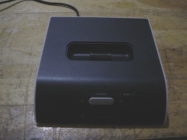
VJS-M812
Jan 08, 2008Wireless Speaker System
Equipment Class
DSS - Part 15 Spread Spectrum Transmitter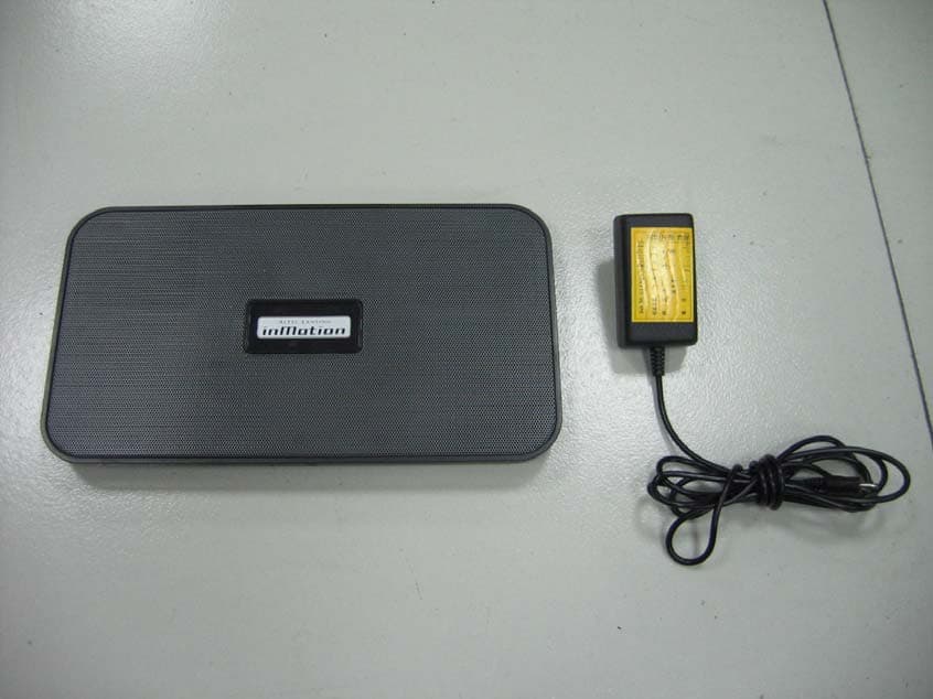
VJS-IMT525
Oct 09, 2007Bluetooth Speaker
Equipment Class
DSS - Part 15 Spread Spectrum Transmitter