VLUST500RFID Reader
Advanced ID Asia Engineering Co. Ltd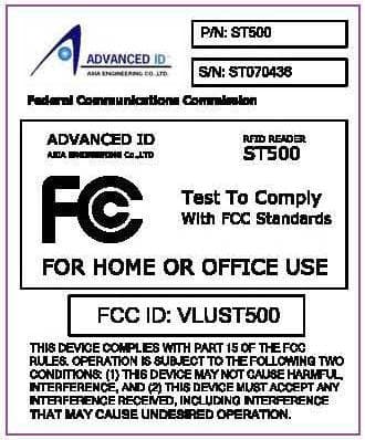
Click to zoom
Application Details
- Equipment Class
- DSS - Part 15 Spread Spectrum Transmitter
- Date of Grant
- Mar 25, 2008
- Application Purpose
- Original Equipment
- Date of Application
- Mar 25, 2008
- Equipment Note
- RFID Reader
- Frequency Range
- 902.30000000 - 927.70000000
- Country
- Thailand
Documents & Files
Document Text
Text extracted from the exhibit documents filed with the FCC. Open a document above to read the original.
Users Manual
Annex No.5 Page 1 of 15 Functional description RFID Reader ST 500 (Users Interface Description) Stand Alone READER ST500 Users Interface Description AFG ASIA ENGINEERING CO.LTD. 65/12 M.10 T.Tonpao A.Sankumpang Chiangmai, Thailand 50130 Tel: +66 53 390 909 Fax: +66 53 390 910 Website : WWW.AAE.CO.TH 2 Contents : 1. Pictures of UHF RFID Stand Alone Reader ST500 ........................................... 3 2. Pre-installation Precautions ............................................................................... 3 3. Abstract .............................................................................................................. 4 4. General descr iption ........................................................................................... 4 5. Operation ........................................................................................................... 4 5.1 Read Tags ................................................................................................... 4 5.2 Writing data to Tag ...................................................................................... 5 5.3 Downloading records fr om the reader ......................................................... 5 5.3.1 Downloading thr ough RS232 ................................................................ 5 5.3.2 Other download po ssibilitie s ................................................................. 5 6. Configuration ..................................................................................................... 5 6.1 Data length and Start address ..................................................................... 5 6.2 Read mode .................................................................................................. 5 6.3 Reader Timeout ........................................................................................... 5 6.4 Operation mode ........................................................................................... 6 6.5 Communication mode .................................................................................. 6 6.6 LED .............................................................................................................. 6 6.7 Date format .................................................................................................. 6 7. Support software (PC Applications)................................................................... 6 7.1 Dot Net Frame work 2 (m anual installation) ................................................ 7 7.2 RFID Note (manual installation) ................................................................... 7 7.2.1 Installation RF ID Note ........................................................................... 7 7.2.2 Start RFID Note .................................................................................... 8 7.2.3 Connection tab (checking Re ader connection) ..................................... 8 7.2.4 Download tab ........................................................................................ 9 7.2.5 Reader Setti ng tab .............................................................................. 10 7.2.5.1 Clock .............................................................................. 10 7.2.5.2 Data length and Start address ......................................... 10 7.2.5.3 Owner and Reader ID ..................................................... 10 7.2.5.4 Control functions ................................................................ 10 7.2.6 Write EPC ta g tab ............................................................................... 11 7.2.6.1 Set data length and start address ..................................... 11 7.2.6.2 Program EPC number ..................................................... 11 7.2.6.3 Write memory data ......................................................... 11 7.2.6.4 Unlock and kill tag ......................................................... 11 7.2.7 Write ISO ta g tab ................................................................................ 12 7.2.7.1 Set data length and start address ..................................... 12 7.2.7.2 Write memory data ......................................................... 12 7.2.8 Tag Note Tab ...................................................................................... 13 7.2.9 Help tab ............................................................................................... 13 8. FCC Statement ................................................................................................ 13 Revision Index Revision Date A uthor Change Record 1_00 2008-01-08 Saran Yimsricharoenkit - 1_01 2008-03-13 Soemsak Lpps - FCC Statement 3 1. Pictures of UHF RFID Stand Alone Reader ST500 2. Pre-installation Precautions Take note of the following precautions before you connect the RFID Reader components together or change any RFID Reader setting precautions before you connect the RFID Reader components together or change any RFID Reader setting • Don’t open any of the components. Opening them may cause severe damage to the reader and components. • Hold or fix Stand Alone reader tightly and don’t drop any components ( they are breakable ). • Set OWNER ID first and be sure the owner ID is NOT NULL .( see owner ) • “Configuration Setting” is ONLY for advanced users. Users who want to use these features MUST follow instructions carefully and take responsibility for any damages that may result. “Use it at your own risk”. Front of Stand Alone Reader and components DC power connector DB9 connector Antenna Status LED Package Contents 1. Stand Alone Reader ST500 ( please see left pictures ) 2. RS232 Communication cable 3. Switching Power supply 4. Support CD 4 • Default setting: Owner ID / Physical Location data entry is ASCII, reading type is ISO and EM. 3. Abstract This document describes the user inte rface of the Stand Alone RFID reader ST500 for release 1.03 and further. 4. Gen…
Text truncated - open the document above for the full version.
Cover Letter(s)
FCC, Request for non-disclosure Date: 21-07-05 RF_501, Issue 3 Page 1 of 1 m.dudde hochfrequenz-technik Rottland 5a 51429 Bergisch Gladbach Germany +49-2207-9689-0 +49-2207-9689-20 [email protected] http://www.dudde.com To: Telefication B.V. Attn: Dept. FCC TCB Edisonstraat 12A 6902 PK ZEVENAAR The Netherlands Subject: Request for confidentiality FCC ID: VLUST500 Reference number: Aee07/242 Dear FCC TCB, Persuant to 47 CFR Section 0.459(a) & (b), m.dudde hochfrequenz-technik hereby requests non- disclosure and confidential treatment of the following materials submitted in support of FCC certification application for FCC ID: VLUST500 Block Diagrams Schematic Diagrams Technical description Antenna description Above materials contain secrets, proprietary and technical information, which would customarily be quarded from competitors under 47 CFR, section 0.457(d)(2). Disclosure or publication or any portion of this company confidential material to other parties could cause substantial competitive harm and provide unjustified benefits for competitors. m.dudde hochfrequenz-technik understands that pursuant to 47 CFR section 0.457(d)(1)(ii) disclosure of the applicant and all accompanying documentation will not be made before the date of the grant. 03.01.2008 Bergisch Gladbach Ralf Trepper
External Photos
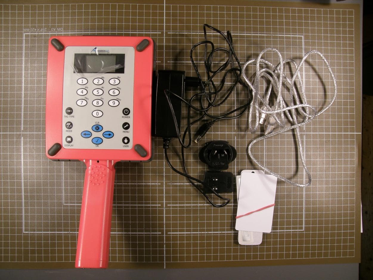
Annex No.1 Page 1 of 2 External photographs of the Equipment Under Test EXTERNAL FRONT VIEW PHOTO Annex No.1 Page 2 of 2 EXTERNAL REAR VIEW PHOTO
ID Label/Location Info
Annex No.4 Page 1 of 2 Sketch of label location Annex No.4 Page 2 of 2 Label sample
Internal Photos
Annex No.2 Page 1 of 5 Internal photographs of the Equipment Under Test Annex No.2 Page 2 of 5 Annex No.2 Page 3 of 5 Annex No.2 Page 4 of 5 Photographs of SkyeModule M9 Annex No.2 Page 5 of 5
RF Exposure Info
MPE calculation RFID Reader ST 500 Regulation 15.247(b) The maximum peak conducted output power of the intentional radiator shall not exceed the following: (4) The conducted output power limit specified in paragraph (b) of this section is based on the use of antennas with directional gains that do not exceed 6 dBi. Except as shown in paragraph (c) of this section, if transmitting antennas of directional gain greater than 6 dBi are used, the conducted output power from the intentional radiator shall be reduced below the stated values in paragraphs (b)(1), (b)(2), and (b)(3) of this section, as appropriate, by the amount in dB that the directional gain of the antenna exceeds 6 dBi. Result The EUT will only be used with a separation of 20 centimetres or greater between the antenna and the body of the user. The MPE calculation for this exposure is shown below. The peak radiated output power (EIRP) is calculated as follows: EIRP = P + G Where, EIRP = 27.1 dBm P = Power input to the antenna (mW) G = Power gain of the antenna (dBi) The numeric gain (G) of the antenna with a gain specified in dB is determined by: G = Log -1 (dB antenna gain / 10) G = Log -1 (xx / 10) G = xx Power density at the specific separation: S = PG/(4R 2 π) Where, S = Maximum power density (mW/cm 2 ) S = (512.86) / (4 * 20 2 * π) P = Power input to the antenna (mW) G = Numeric power gain of the antenna S = 0.102 mW/cm 2 R = Distance to the center of the radiation of the antenna (20cm = limit for MPE) The maximum permissible exposure (MPE) for the general population is 1 mW/cm 2 . The power density at 20cm does not exceed the 1 mW/cm 2 limit. Estimated safe separation: R = √(PG/4л) Where, P = Power input to the antenna (mW) R = √(512.86/4л) G = Numeric power gain of the antenna) R = 6.39 cm R = Distance to the center of the radiation of the antenna (20cm = limit for MPE) R = 2.02 cm R = Distance to the backside of the radiation of the antenna (EIRP 10 dB below the center of radiation) (20cm = limit for MPE)
Test Report
Test report no. 07004490 Page 1 of 40 EUT: RFID Reader ST 500 FCC ID: VLUST500 Date of issue: 2007-12-11 m. dudde hochfrequenz-technik Rottland 5a Vers. no. 1.07 D-51429 Bergisch Gladbach Tel.: +49 2207-9689-0 Fax: +49 2207 9689-20 e-mail: [email protected] http://www.dudde.com DAT-P-225/96-02 Test Report acc. to the relevant standard 47 CFR Part 15 C – Intentional Radiators Measurement Procedure: ANSI C63.4 - 1992 relating to Advanced ID Asia Engineering Co. Ltd. RFID Reader ST 500 Measurement of Radio- Noise Emissions from Low- Voltage Electrical and Electronic Equipment Technical characteristics and test methods for radio equipment in the frequency range 9 kHz to 40 GHz Test report no. 07004490 Page 2 of 40 EUT: RFID Reader ST 500 FCC ID: VLUST500 Date of issue: 2007-12-11 m. dudde hochfrequenz-technik Rottland 5a Vers. no. 1.07 D-51429 Bergisch Gladbach Tel.: +49 2207-9689-0 Fax: +49 2207 9689-20 e-mail: [email protected] http://www.dudde.com Manufacturer’s details Manufacturer Advanced ID Asia Engineering Co. Ltd. Manufacturer’s grantee code VLU 65/12 Moo 10 T. Sankumpang A. Sankumpang Chiang Mai 501030 Thailand +66 53 39 09 09 +66 53 39 09 10 Manufacturer’s address [email protected] 47 CFR Part 15C - Intentional Radiators Relevant standard used ANSI C63.4-1992 Test Report prepared by Ralf Trepper m.dudde hochfrequenz-technik (laboratory) Rottland 5a 51429 Bergisch Gladbach Germany Phone: +49 2207 96890 Fax: +49 2207 968920 Technical engineer E-mail: [email protected] Equipment Under Test (EUT) Equipment category RFID reader Trade name Advanced ID Corporation Type designation RFID Reader ST 500 Serial no. 376597 --- Variants Test report no. 07004490 Page 3 of 40 EUT: RFID Reader ST 500 FCC ID: VLUST500 Date of issue: 2007-12-11 m. dudde hochfrequenz-technik Rottland 5a Vers. no. 1.07 D-51429 Bergisch Gladbach Tel.: +49 2207-9689-0 Fax: +49 2207 9689-20 e-mail: [email protected] http://www.dudde.com 1. Test results CFR Section Report Chapter Requirements Headline Test result 15.203 11.1 Antenna requirement pass fail n.t. 15.205(a) 11.2 Operation in the restricted bands pass fail n.t. 15.207 11.3 Conducted emissions pass fail n.t. 15.209(a) 11.4 Radiated emissions pass fail n.t. 15.247(a)(1)(i) 11.5 Channel occupancy / bandwidth pass fail n.t. 15.247(b)(2) 11.6 Peak output power pass fail n.t. 15.247(b)(4) 11.7 Radio frequency hazard pass fail n.t. 15.247(d) 11.8 Out of band emissions pass fail n.t. Test requirements kept yes no Signature (Technical engineer) Ralf Trepper Signature (Manager) Manfried Dudde Test report no. 07004490 Page 4 of 40 EUT: RFID Reader ST 500 FCC ID: VLUST500 Date of issue: 2007-12-11 m. dudde hochfrequenz-technik Rottland 5a Vers. no. 1.07 D-51429 Bergisch Gladbach Tel.: +49 2207-9689-0 Fax: +49 2207 9689-20 e-mail: [email protected] http://www.dudde.com List of contents Page 1. Test results....................................................................................................................................................3 2. Test laboratory ..............................................................................................................................................6 3. Introduction..................................................................................................................................................6 4. Product.........................................................................................................................................................7 5. Test schedule ................................................................................................................................................7 6. Product and measurement documentation......................................................................................................8 7. Observations and comments..........................................................................................................................8 8. Summary ......................................................................................................................................................8 9. Conclusions .................................................................................................................................................9 10. Operation description..................................................................................................................................10 11.1 Antenna requirement ................................................................................................................................11 11.1.1 Regulation .......................................................................................................................................11 11.1.2 Result...............................................................................................................................................11 11.2 Operation in the restricted bands .............................................................................................................12 11.2.1 Regulation .......................................................................................................................................12 11.2.2 Result...............................................................................................................................................14 11.3 Conducted emissions ...............................................................................................................................15 11.3.1 Regulation .......................................................................................................................................15 11.3.2 Test equipment ................................................................................................................................16 11.3.3 Test procedures ...................................................................................…
Text truncated - open the document above for the full version.
Test Report
Annex No.3 Page 1 of 4 Channel occupancy / bandwidth plots Annex No.3 Page 2 of 4 Annex No.3 Page 3 of 4 Annex No.3 Page 4 of 4
Test Setup Photos
Annex No.6 Page 1 of 2 Test setup photos Annex No.6 Page 2 of 2
Contact Information
Applicant
Gottfried Auer
Technical Contact
m.dudde hochfrequenz-technikRalf Trepper
[email protected]+49 (0)2207 9789-0
Rottland 5a · Bergisch Gladbach · Germany
Test Firm
m. dudde hochfrequenz-technikManfred Dudde
Technical Specifications
| # | Rule Parts | Frequency Range | Power Output |
|---|---|---|---|
| 1 | 15C | 902.3 MHz - 927.7 MHz | 510.00 mW |
Other Applications from Advanced ID Asia Engineering Co. Ltd
VLUST110
Mar 10, 2010RFID Reader
Equipment Class
DSS - Part 15 Spread Spectrum Transmitter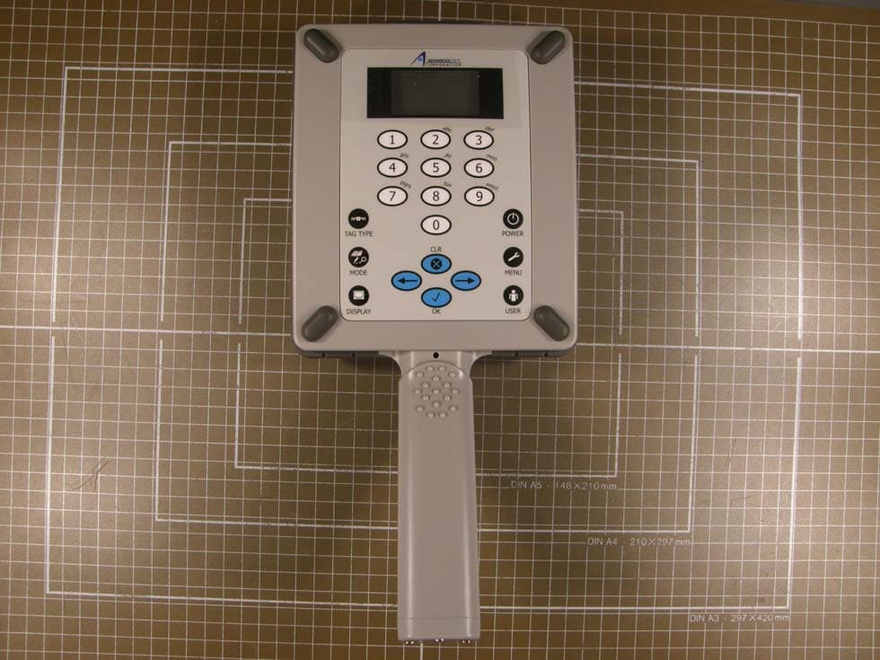
VLUST510
Mar 07, 2010RFID Reader
Equipment Class
DSS - Part 15 Spread Spectrum Transmitter
VLUHH500
Mar 25, 2008RFID Reader HH 500 / PR 500
Equipment Class
DSS - Part 15 Spread Spectrum Transmitter