VLUST510RFID Reader
Advanced ID Asia Engineering Co. Ltd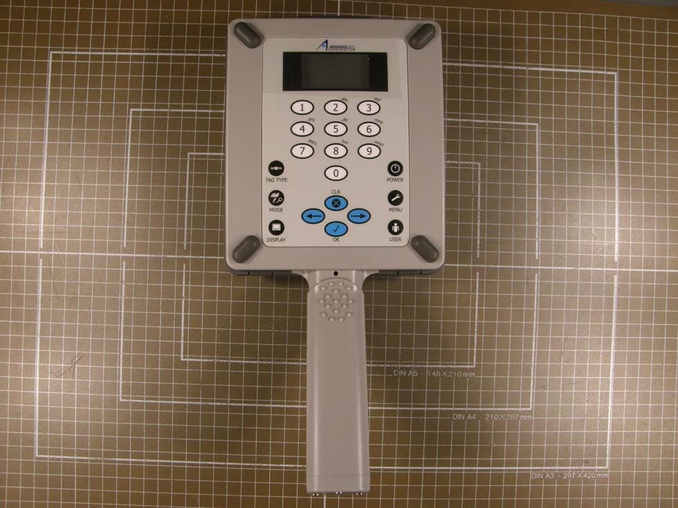
Click to zoom
Application Details
- Equipment Class
- DSS - Part 15 Spread Spectrum Transmitter
- Date of Grant
- Mar 07, 2010
- Application Purpose
- Original Equipment
- Date of Application
- Mar 07, 2010
- Equipment Note
- RFID Reader
- Frequency Range
- 902.50000000 - 927.00000000
- Country
- Thailand
Documents & Files
Document Text
Text extracted from the exhibit documents filed with the FCC. Open a document above to read the original.
Users Manual
Annex No.5 Page 1 of 90 Functional description / User manual PR110/PR510 ST110/ST510 PR110 PR510 USER MANUAL Rev 1 .02 1/ 21/2009 2 Contents Contents .......................................................................................................................... 2 Revision Index .................................................................................................................. 4 About This Manual ........................................................................................................... 5 Service Information ......................................................................................................... 5 Product Overview ............................................................................................................ 5 Getting Start .................................................................................................................... 6 Wake Up Reader .......................................................................................................... 6 Change Reading/Writing Mode .................................................................................... 6 Change Reading/Writing Memory Bank ....................................................................... 6 Change Reading/Writing Memory Offset ..................................................................... 6 Change Settings ........................................................................................................... 7 Communication to PC ...................................................................................................... 8 Physical layer ............................................................................................................... 8 Data Link Layer ............................................................................................................. 8 Command structure ..................................................................................................... 9 Command Descriptions .................................................................................................. 10 Error Message (FF) ..................................................................................................... 10 Get Firmware Version (00) ......................................................................................... 11 Get Hardware Version (01) ........................................................................................ 12 Get Reader ID (02) ..................................................................................................... 13 Get Reader Model (03)............................................................................................... 14 Get Reader Status (04) ............................................................................................... 15 Set Tag Type (10) ....................................................................................................... 17 Set Bank (11) .............................................................................................................. 19 Set Start Address (12) ................................................................................................ 21 3 Set Data Length (13) .................................................................................................. 23 Get Tag Type (20) ....................................................................................................... 25 Get Bank (21) ............................................................................................................. 26 Get Start Address (22) ................................................................................................ 28 Set Data Length (23) .................................................................................................. 30 Stop operation (30) .................................................................................................... 32 Start Auto-Reading (31) ............................................................................................. 33 Polling Read (32) ........................................................................................................ 35 Write Data or ID (40) .................................................................................................. 37 Lock (50) .................................................................................................................... 40 Kill (51) ....................................................................................................................... 42 Support Software for PR110 and PR510 ......................................................................... 44 Software requirement ................................................................................................ 44 ST-PR Demo Software ................................................................................................ 44 1. Installation ST-PR Demo Software ...................................................................... 44 2. Using ST-PR Demo Software ............................................................................... 45 3. Readers Connection ........................................................................................... 46 4. Read tag data using Log tab ............................................................................... 47 5. Write data to a tag using Writing tab ................................................................. 48 6. Download data from Reader’s memory using Download tab ............................. 49 FCC Statement ............................................................................................................... 51 FCC Radiation Exposure Statement: ........................................................................... 52 Declaration of Conformity for USA ............................................................................. 52 4 Revision Index …
Text truncated - open the document above for the full version.
Cover Letter(s)
m. dudde hochfrequenz-technik Rottland 5a, D-51429 Bergisch-Gladbach DIN EN ISO/IEC 17025 zertifiziert Akkreditiertes Testhaus- Reg.-Nr.: DAT-P-225/96-02 Tel. : +49 22 07 - 96 89 - 0 Fax : +49 22 07 - 96 89 - 20 email: [email protected] www.dudde.com PHOENIX TEST-LAB GmbH Product Certification Königswinkel 10 D 32825 Blomberg Date: 2010-02-22 FCC ID: VLUST510 Subject: Attestation Letter “Declaration of Conformity” Dear Sirs, The products with the above FCC ID are defined as composite device. The transmitter is authorized under the “Certification” procedure. The device is also defined as “PC Periphery” acc to §15.101 Equipment authorization of unintentional radiators, where we hereby declare on behalf of our customer Advanced ID Asia Engineering Co. Ltd., that we apply and follow the “Declaration of Conformity” procedure. If you have any questions, please feel free to contact me at the address shown below. Yours sincerely, Andreas Morsbach Assistant Manager m. dudde hochfrequenz-technik Rottland 5a 51429 Bergisch Gladbach Tel.: +49 (0) 2207/9689-18 Fax: +49 (0) 2207/9689-20 E-Mail: [email protected]
Cover Letter(s)
m. dudde hochfrequenz-technik Rottland 5a, D-51429 Bergisch-Gladbach DIN EN ISO/IEC 17025 zertifiziert Akkreditiertes Testhaus- Reg.-Nr.: DAT-P-225/96-02 Tel. : +49 22 07 - 96 89 - 0 Fax : +49 22 07 - 96 89 - 20 email: [email protected] www.dudde.com Request for Confidentiality Date: 2010-02-09 RE: Certification Application FCC ID: VLUST510 Confidentiality Request To whom it may concern: Persuant to Sections 0.457 (d) (1) (ii) and 0.459 of the Commission’s Rules, our customer hereby requests confidential treatment of information accompanying as outlined below: Operational description Schematics Parts list Block diagram The above materials contain trade secrets and proprietary information not customarily released to the public. The public disclosure of these matters might be harmful to our customer and provide unjustified benefits to their competitors. Thank you for your attention in this matter. m. dudde hochfrequenz-technik Andreas Morsbach Assistant Manager
External Photos
Annex No.1 Page 1 of 5 External photographs of the Equipment Under Test EXTERNAL FRONT VIEW PHOTO PR510 Annex No.1 Page 2 of 5 EXTERNAL REAR VIEW PHOTO PR510 Annex No.1 Page 3 of 5 EXTERNAL SIDE VIEW PHOTO PR510 Annex No.1 Page 4 of 5 EXTERNAL FRONT VIEW PHOTO ST510 Annex No.1 Page 5 of 5 EXTERNAL REAR VIEW PHOTO ST510
Internal Photos
Annex No.2 Page 1 of 7 Internal photographs of the Equipment Under Test INTERNAL UPPER SIDE PHOTO PR510 Annex No.2 Page 2 of 7 INTERNAL LOWER SIDE PHOTO PR510 Annex No.2 Page 3 of 7 INTERNAL SIDE PHOTOS PR510 transmitter front Annex No.2 Page 4 of 7 INTERNAL SIDE PHOTOS PR510 transmitter rear Annex No.2 Page 5 of 7 INTERNAL SIDE PHOTOS ST510 Antenna Annex No.2 Page 6 of 7 INTERNAL SIDE PHOTOS ST510 transmitter front Annex No.2 Page 7 of 7 INTERNAL SIDE PHOTOS ST510 transmitter rear
RF Exposure Info
MPE calculation Page 1 of 1 EUT: RFID Reader ST510 Date of issue: 2010-02-10 m. dudde hochfrequenz-technik Rottland 5a Vers. no. 1.10 D-51429 Bergisch Gladbach Tel.: +49 2207-9689-0 Fax: +49 2207 9689-20 e-mail: [email protected] http://www.dudde.com MPE calculation to the FCC ID: VLUST510 These equations are generally accurate in the far field of an antenna but will over predict power density in the near field, where they could be used for making a “worst case” prediction. S = PG/4πR 2 where S = power density ( in appropriate units, e.g. mW/cm2) P = power input to the antenna (in appropriate units e.g. mW) G = power gain of the antenna in the direction of interest relative to the isotropic radiator R = distance to the center of radiation of the antenna (appropriate units e.g. cm) Or S = EIRP/4πR 2 where EIRP = equivalent isotropically radiated power Calculation: (Calculated for max. EIRP) EIRP: 28.5 dBm = 707.9 mW calculated at distance of 20 cm: power density = 707.9 /4π20 2 = 0.1408 mW/ cm 2 Limit: Signature (Technical engineer) Ralf Trepper 0.6 mW/cm 2 is the reference level for general public exposure according to the OET Bulletin 65, Edition 97-01 Table 1.
Test Report
Test report no. 10005932a Page 1 of 43 EUT: RFID Reader ST510 / PR510 FCC ID: VLUST510 Date of issue: 2010-02-03 m. dudde hochfrequenz-technik Rottland 5a Vers. no. 1.07 D-51429 Bergisch Gladbach Tel.: +49 2207-9689-0 Fax: +49 2207 9689-20 e-mail: [email protected] http://www.dudde.com DAT-P-225/96-02 Test Report acc. to the relevant standard 47 CFR Part 15 C – Intentional Radiators Measurement Procedure: ANSI C63.4 - 2003 relating to Advanced ID Asia Engineering Co. Ltd RFID Reader ST510 / PR510 Measurement of Radio- Noise Emissions from Low- Voltage Electrical and Electronic Equipment Technical characteristics and test methods for radio equipment in the frequency range 9 kHz to 40 GHz Test report no. 10005932a Page 2 of 43 EUT: RFID Reader ST510 / PR510 FCC ID: VLUST510 Date of issue: 2010-02-03 m. dudde hochfrequenz-technik Rottland 5a Vers. no. 1.07 D-51429 Bergisch Gladbach Tel.: +49 2207-9689-0 Fax: +49 2207 9689-20 e-mail: [email protected] http://www.dudde.com Manufacturer’s details Manufacturer Advanced ID Asia Engineering Co. Ltd. Manufacturer’s grantee code VLU Manufacturer’s address 116 Moo 3 T. Maekhue, A. Doisaket Chiang Mai 50220 Thailand Mr. Gottfried Auer Phone: +66 811738779 Fax: +66 53387319 E-mail: [email protected] Relevant standard used 47 CFR Part 15C - Intentional Radiators ANSI C63.4-2003 Test Report prepared by Technical engineer Ralf Trepper m.dudde hochfrequenz-technik (laboratory) Rottland 5a 51429 Bergisch Gladbach Germany Phone: +49 2207 96890 Fax: +49 2207 968920 E-mail: [email protected] Equipment Under Test (EUT) Equipment category FHSS Transceiver Trade name ADVANCED ID Type designation ST510USB / PR510 Serial no. 20522300911000002 / 3052300911000002 Variants USB Reader (ST510USB) Pocket Reader (PR510) Test report no. 10005932a Page 3 of 43 EUT: RFID Reader ST510 / PR510 FCC ID: VLUST510 Date of issue: 2010-02-03 m. dudde hochfrequenz-technik Rottland 5a Vers. no. 1.07 D-51429 Bergisch Gladbach Tel.: +49 2207-9689-0 Fax: +49 2207 9689-20 e-mail: [email protected] http://www.dudde.com 1. Test results CFR Section Report Chapter Requirements Headline Test result 15.203 11.1 Antenna requirement pass fail n.t. 15.205(a) 11.2 Operation in the restricted bands pass fail n.t. 15.209(a) 11.4 Radiated emissions pass fail n.t. 15.247(a)(1)(i) 11.5 Channel occupancy / bandwidth pass fail n.t. 15.247(b)(2) 11.6 Peak output power pass fail n.t. 15.247(b)(4) 11.7 Radio frequency hazard pass fail n.t. 15.247(d) 11.8 Out of band emissions pass fail n.t. 15.207 11.9 Conducted limits pass fail n.t. Test requirements kept yes no Signature (Technical engineer) Ralf Trepper Signature (Manager) Manfried Dudde Test report no. 10005932a Page 4 of 43 EUT: RFID Reader ST510 / PR510 FCC ID: VLUST510 Date of issue: 2010-02-03 m. dudde hochfrequenz-technik Rottland 5a Vers. no. 1.07 D-51429 Bergisch Gladbach Tel.: +49 2207-9689-0 Fax: +49 2207 9689-20 e-mail: [email protected] http://www.dudde.com List of contents Page 1. Test results ................................................................................................................................................... 3 2. Test laboratory ............................................................................................................................................. 6 3. Introduction .................................................................................................................................................. 6 4. Product ......................................................................................................................................................... 7 5. Test schedule ................................................................................................................................................ 7 6. Product and measurement documentation .................................................................................................... 8 7. Observations and comments ......................................................................................................................... 8 8. Summary ...................................................................................................................................................... 8 9. Conclusions ................................................................................................................................................. 9 10. Operation description ................................................................................................................................. 10 11.1 Antenna requirement ................................................................................................................................ 11 11.1.1 Regulation ....................................................................................................................................... 11 11.1.2 Result ............................................................................................................................................... 11 11.2 Operation in the restricted bands ............................................................................................................. 12 11.2.1 Regulation ....................................................................................................................................... 12 11.2.2 Result ............................................................................................................................................... 14 11.3 Radiated emissions .................................................................................................................................. 15 11.3.1 Regulation ....................................................................................................................................... 15 11.3.2 Test equipment .............................................................................................…
Text truncated - open the document above for the full version.
Test Report
Annex No.3 Page 1 of 1 Occupied bandwidth plot
Test Report
Annex No.11 Page 1 of 4 Channel occupancy 50 hopping channels between 902.5 MHz and 927.0 MHz with a channel spacing of 500 kHz Annex No.11 Page 2 of 4 Lowest Channel 902.500 MHz maximum 1 hops in a 20 sec period shortest single hop measured longest single hop measured Annex No.11 Page 3 of 4 Middle Channel 914.500 MHz maximum 1 hops in a 20 sec period shortest single hop measured longest single hop measured Annex No.11 Page 4 of 4 Highest Channel 927.000 MHz maximum 1 hops in a 20 sec period shortest single hop measured longest single hop measured
Test Report
Annex No. 12 Page 1 of 3 Antenna Description ST510 / PR510 Annex No. 12 Page 2 of 3 Antenna for UHF RFID reader ST 510; PR 510 1 Antenna type: circular patch antenna 5x5 inch outline dimension with two quadrature inputs. 2 Electrical characteristics: Impedance: 50 Ohm matched for a frequency range of 900 to 930 MHz; or alternatively for 850 to 880 MHz VSWR: less than 1:1,5 Gain: 5 dBi Directivity: at 7,5 dBi 3 Radiation pattern: 4 Schematic: see PDF file enclosed 5 Mechanical construction: see pictures below The main elements are a steel brass frame which is the carrier for the antenna and ground; a Styrofoam distance holder between the brass frame and the FR4 PCB antenna. The coupling device is directly soldered onto the brass frame and the antenna is connected with 2 steel PIN’s through the brass frame and distance holder to the PCB antenna. Annex No. 12 Page 3 of 3 Antenna explosion view Antenna back view Top view,
Test Setup Photos
Annex No.6 Page 1 of 12 Test setup photos ST510 Annex No.6 Page 2 of 12 ST510 Annex No.6 Page 3 of 12 ST510 Annex No.6 Page 4 of 12 ST510 Annex No.6 Page 5 of 12 ST510 Annex No.6 Page 6 of 12 ST510 Annex No.6 Page 7 of 12 PR510 Annex No.6 Page 8 of 12 PR510 Annex No.6 Page 9 of 12 PR510 Annex No.6 Page 10 of 12 PR510 Annex No.6 Page 11 of 12 PR510 Annex No.6 Page 12 of 12 PR510
Contact Information
Applicant
Gottfried Auer
Test Firm
m. dudde hochfrequenz-technikManfred Dudde
Technical Specifications
| # | Rule Parts | Frequency Range | Power Output |
|---|---|---|---|
| 1 | 15C | 902.5 MHz - 927 MHz | 708.00 mW |
Other Applications from Advanced ID Asia Engineering Co. Ltd
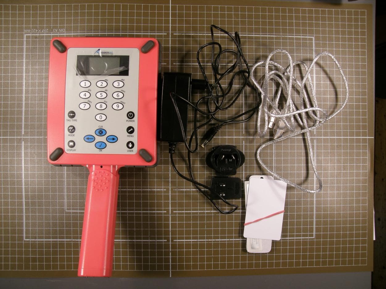
VLUST110
Mar 10, 2010RFID Reader
Equipment Class
DSS - Part 15 Spread Spectrum Transmitter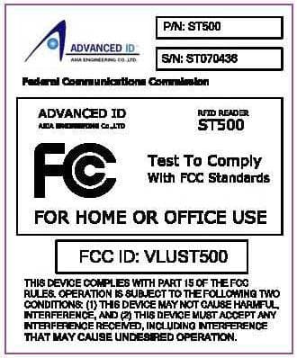
VLUST500
Mar 25, 2008RFID Reader
Equipment Class
DSS - Part 15 Spread Spectrum Transmitter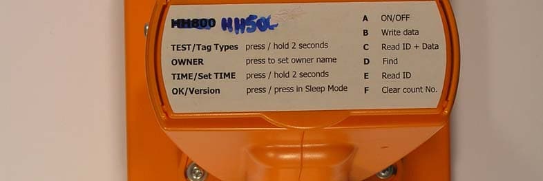
VLUHH500
Mar 25, 2008RFID Reader HH 500 / PR 500
Equipment Class
DSS - Part 15 Spread Spectrum Transmitter