VOI-ANMKNN3RTR-01Mobile Router
Autonet MobileApplication Details
- Equipment Class
- DSS - Part 15 Spread Spectrum Transmitter
- Date of Grant
- Aug 18, 2014
- Application Purpose
- Original Equipment
- Date of Application
- Aug 18, 2014
- Equipment Note
- Mobile Router
- Frequency Range
- 2402.00000000 - 2480.00000000
- Company
- Autonet Mobile
- Country
- United States
Documents & Files
Document Text
Text extracted from the exhibit documents filed with the FCC. Open a document above to read the original.
Users Manual
Stewart, User’s Guide, Autonet Document Number 186-1100-001 Date Effective: May 21, 2009 Rev: 04 Page 1 of 46 CONFIDENTIAL 186_1100_001_04.doc 1. PURPOSE The purpose of this document is to provide specifications for the CarFi User’s guide for the Stewart Autonet branded router. 2. SCOPE This document applies to the fabrication and assembly of the Stewart CarFi User’s guide. 3. RESPONSIBILITIES It is the responsibility of contract manufacturer/packaging supplier to follow this document, or create an approved internal document. 4. DEFINITIONS 4.1. Stewart: Internal name for the second generation Autonet router. 5. APPLICABLE DOCUMENTS All data is included in this file. 6. DIMENSIONS OD height: 5 inches OD Width: 5 inches 7. MATERIALS/PROCESS Cover: Base material: 100 lb Hammermill Gloss Cover Color: Black Pages included: Front/blank page, Back/inside of page Inside content: 28lb Hammermill Text Color: Black Pages included: 1 thru page 40 (not numbered pages but actual pages) Fabrication: Book style, folded and stapled-2 places Note, first 2 pages of this document are not printed in guide-reference only on fabrication Stewart, User’s Guide, Autonet Document Number 186-1100-001 Date Effective: May 21, 2009 Rev: 04 Page 2 of 46 CONFIDENTIAL 186_1100_001_04.doc 8. TESTING TBD 9. REVISION SYNOPSIS Name Description Revision Date dbl Initial release 01 May 21, 2009 dbl Updated content, format, etc. 02 April 22, 2010 dbl Updated content, format, etc. 03 December 16, 2010 dbl Updated page 1 and 44 04 January 12, 2011 10. Approvals Approval Name Date Title CarFi Users Guide Introducing the Autonet Mobile CarFi Hotspot Thank you for purchasing Autonet Mobile’s CarFi hotspot, designed specifically for the stringent demands of mobile vehicles. The advantages of Autonet Mobile are reliable seamless internet connections wherever you are and whenever you need them most, in your car. Whether it’s the patent-pending TRU Technology keeping your connections from losing signals between cell towers, tunnels, or areas of poor reception, or the dedicated and diligent customer service providing support for your network, devices or billing in our centralized local call center, Autonet Mobile is dedicated in providing you world class and unparalleled service and products. Autonet Mobile CarFi: “It’s the Internet on Wheels” CarFi Overview 1 Quickstart guide 5 Configuring the CarFi 6 Configuring Wireless Settings 7 Configuring Security Settings 10 Disabling Login Screen 11 Changing the password 11 Checking Connection status 12 Troubleshooting guide 13 Service Information 15 Technical Specifications 16 Installation Instructions 18 Care and Maintenance 21 Regulatory Information 22 Safety Information 23 Accepted Use Policy 28 Autonet Software License 32 Limited Warranty 35 Legal Disclosure 37 Table of contents The Autonet Mobile CarFi Hotspot Overview Package Contents: CarFi Unit and docking station User’s guide included in the package Installation kit or installation cable Activation guide Snapshot of features Reliable TRU technology yielding maximum connection uptime Maximum reliability, featuring ruggedized device designed specifically for automotive applications Docking station for vehicle-vehicle mobility (must purchase additional dock for this application) I/O’s: 2 x USB ports, Ethernet port Memory-1G internal, CF slot for additional memory FCC compliant & OEM Automotive approved Remote administration monitoring, configuring and firmware updates Compatible with all major OS: Windows, OSX, Linux, Solaris Device compatibility: works with any WiFi device such as desktops, laptops, handset, s, servers, POS systems, ATM machines, remote security, sensing/metering devices 1 About your CarFi 1. External cellular antenna-TNC 2. Complete unit with dock 5. Power cable/harness 3. Blue indicator LED 1 2 3 5 2 4 4. Pushbutton for undocking CarFi USB About your CarFi continued 1 2 3 1. Ethernet port 2. (2) USB ports 4 4. TNC antenna connector 3. Compact Flash slot 5 6 5. Dock mounting holes (4) 6. Pushbutton for undocking CarFi 3 4 For technical support please call Autonet Mobile customer service center: 1-800-977-2107 Autonet Mobile assumes no responsibility for the configurations, security, or data files on your wireless device resulting from connection to Autonet Mobile’s network. Anti-virus, privacy and security protection is the responsibility of the user. Do not operate CarFi while driving or perform any function that takes your attention away from safely operating your vehicle. Any function that requires prolonged attention should be performed after coming to a complete stop. Always stop the vehicle in a safe location before performing these functions. Failure to do so may result in an accident. If CarFi is found, please call: 1-800-977-2107. The CarFi is automatically disabled if reported lost or stolen. Step 4 Happy Surfing! (Please note: You must complete an Autonet service agreement in order to activate CarFi. The Autonet service agreement can be found at: https://www.autonetmobile.com/signup 5 Quickstart Guide Step 1 Turn your car to the Acc position to power up Autonet Mobile’s CarFi. Step 2 Open your wireless network list and connect to “autonet-XXXX”. (The last 4 digits will be the same as your last 4 digits of CarFi serial number). Step 3 Open your web browser. Click on the login button. 6 Configuring CarFi It is highly recommended to enable “encryption type/key security” and change the default password for CarFi Configuring CarFi’s settings Step 1 Locate CarFi’s ten digit serial number located on the back side of CarFi, or in front of the User’s guide included in the package. (If you have trouble locating the serial number of the CarFi, please call our customer support line at 1-800-977-2107 for assistance) Step 2: Open a web browser and go to: http://www.autonetrouter.com/admin Login with username “autonet” and use CarFi’s serial number as the password (e.g. 0024C76258). Click on the l…
Text truncated - open the document above for the full version.
Users Manual
Important Product Information GuideAut onet Mobile customer support line: 1-800-977-2107 © 2014 Aut onet Mobile, Inc. P/N: 186-1100-001 Rev. 06 Important Product Information Guide Welcome Quickstart Guide Configuring the In-Car Router Configuring Wireless Settings Configuring Wireless Security Settings Configuring Login Screen Changing the Password on Your In-Car Router Checking the Connection Status of the In-Car Router Troubleshooting Guide Safety Policy Acceptable Use Policy Autonet Mobile Software License Autonet Mobile Limited Warranty and Liability Legal Disclosure 2 4 5 6 9 10 11 12 13 14 20 24 26 27 23 Welcome to Autonet Mobile To activate your account with Autonet Mobile, please submit a completed service agreement online or by fax. Online Go to https://signup.autonetmobile.com Fax Download the service agreement from: https://signup autonetmobile.com and fax the completed agreement to 415-840-1725. If you have any questions please call 1-800-977-2107. For technical support call the Autonet Mobile customer service center: 1-800-977-2107. Autonet Mobile assumes no responsibility for the configurations, security, or data files on your wireless device resulting from connection to Autonet Mobile’s network. Anti-virus, privacy and security protection is the responsibility of the user. Do not operate the In- Car Router while driving or perform any function that takes your attention away from safely driving your vehicle. Any function that requires prolonged attention should be performed after coming to a complete stop. Always stop the vehicle in a safe location before performing these functions. Failure to do so may result in an accident. If the In-Car Router is found, please call: 1-800-977-2107. The router is automatically disabled if lost. 45 Quickstart Guide Step 1 Turn your car to power up Autonet Mobile. Shortly “autonet” will appear in your wireless network list. Step 2 In your wireless network list connect to the wireless network that contains the name “autonet”. Step 3 Open your web browser. Click on the login button. Step 4 Happy surfing! Configuring the In-Car Router It is highly recommended that the user enable WEP security and change the default password on the Autonet Mobile In-Car Router. Configuring the WiFi interface on your In-Car Router The unit’s serial number is is a ten digit hexadecimal number located in 2 places. It is located: 1. On the back of the In-Car Router 2. On the front of the quickstart guide. If you have trouble locating the serial number of the router please call our customer support line at 1-800-977-2107 for assistance. Open a web browser and go to the URL: http://www. autonetrouter.com/admin login as username “autonet” and use the unit’s serial number as the password. (e.g. 0024C76258 ) and click on the “login” button. or 67 Configuring Wireless Settings Click on “Wireless Settings” ESSID Extended Service Set ID. The ESSID is the identifying name of a wireless network - strictly it is the identifying name of a wireless access point. It allows one wireless network to be clearly distinguishable from another. The default ESSID is autonet- XXXX, where XXXX is the last 4 digits of the In-Car Router’s serial number. It is recommended that you keep this ESSID in order to distinguish your router from other routers that may be in the area. WEP key The WEP key is not shown if it is set. You do not have to set it, if you want it to remain the same. To set the current encryption key, just enter the key in hex digits as XXXXXXXXXX. The key must be 10 hex digits, (e.G. 1234567890 ) You can also enter the key as an ASCII string by using the s: prefix. The ASCII string must be five characters, (e.g. s:smile ). To disable WEP, enter “off” as the WEP key. Radio Mode This allows you to select whether the radio is in 802.11b, 802.11g and 802.11a mode. Not all routers support all modes, so only the supported modes for your In-Car Router are shown. Channel Direct communication between an 802.11 Radio card and an access point occurs over a common channel frequency. The FCC allows channels 1 through 11 within the U.S. An important concept to note regarding channel assignments is that the channel actually represents the center frequency that the transceiver within the radio and access point uses (e.g., 2.412 GHz for channel 1 and 2.417 GHz for channel 2). There is only 5 MHz separation between the center frequencies, and an 802.11b signal occupies approximately 30 MHz of the frequency spectrum. The signal falls within about 15 MHz of each side of the center frequency. As a result, an 802.11b signal overlaps with several adjacent channel frequencies. This leaves you with only three channels (channels 1, 6, and 11 for the U.S.) That you can use without causing interference between access points. 89 Bit rate This allows you to set the bit rate in Mbs. The bit rate is the speed at which bits are transmitted over the medium. The user speed of the link is lower due to medium sharing and various overhead. Select a value to lock the card to a particular bit rate. If you specify auto, the driver will use all bit rates to find an optimum rate. RTS threshold RTS/CTS adds a handshake before each packet transmission to make sure that the channel is clear. This adds overhead, but Increases performance in case of hidden nodes or a large number of active nodes. This parameter sets the size of the smallest packet for which the node sends rts; a value equal to the maximum packet size disables the mechanism. You may also set this parameter to off. Fragmentation threshold Fragmentation allows to split an IP packet in a burst of smaller fragments transmitted on the medium. In most cases this adds overhead, but in a very noisy environment this reduces the error penalty and allow packets to get through interference bursts. This parameter sets the maximum fragment size. You may also set this to off to disable the mechanism. TxPower This allows you to set the transmit power of the radio. Setting a…
Text truncated - open the document above for the full version.
Cover Letter(s)
Autonet Mobile, Inc. 1700 Montgomery Ste. 111, San Francisco, CA 94111 Support - 1-800-977-2107 [email protected] www.autonetmobile.com 06/26/2014 MET Laboratories, Inc. 914 West Patapsco Ave. Baltimore, MD 21230 RE: CONFIDENTIALITY REQUEST FOR modem AS-HLRTR-01 with FCC ID VOI-‐ ANMKNN3RTR-‐01 To Whom it May Concern: This letter serves as an official request under FCC Rule Sections 0.457 & 0.459. We have requested that the schematics, BOM, parts list, block diagram of all component, operational description, tune up procedures and all photos of internal components required to be submitted with this application be withheld from public view. The documents are company proprietary information that could never get into the pocession of our competition. Please contact me if there is any information you need. Sincerely, Doug Moeller Chief Technology Officer
Cover Letter(s)
Autonet Mobile, Inc. 1700 Montgomery Ste. 111, San Francisco, CA 94111 Support - 1-800-977-2107 [email protected] www.autonetmobile.com 08/13/14 MET Laboratories, Inc. 914 West Patapsco Ave. Baltimore, MD 21230 RE: DECLARATION FOR modem AS-HLRTR-01 with FCC ID VOI-‐ANMKNN3RTR-‐01 To Whom it May Concern: This letter serves as an official statement that the above mentioned product is compliant with FCC Specifications 15.247g and 15.247h. 15.247 (g) Frequency hopping spread spectrum systems are not required to employ all available hopping channels during each transmission. However, the system, consisting of both the transmitter and the receiver, must be designed to comply with all of the regulations in this section should the transmitter be presented with a continuous data (or information) stream. In addition, a system employing short transmission bursts must comply with the definition of a frequency hopping system and must distribute its transmissions over the minimum number of hopping channels specified in this section. 15.247 (h) The incorporation of intelligence within a frequency hopping spread spectrum system that permits the system to recognize other users within the spectrum band so that it individually and independently chooses and adapts its hopsets to avoid hopping on occupied channels is permitted. The coordination of frequency hopping systems in any other manner for the express purpose of avoiding the simultaneous occupancy of individual hopping frequencies by multiple transmitters is not permitted. Please contact me if there is any information you need. Sincerely, Doug Moeller Chief Technology Officer
RF Exposure Info
Ethertronics, Inc. 1 Prestta Antenna Application Note CONFIDENTIAL AND PROPRIETARY Preliminary Release 5/4/2010 Antenna Application Note Prestta TM Standard Penta- Band Cellular Embedded Antenna P522304 Applications: M2M Automotive Automatic Meter Reading Healthcare Point of Sale Tracking 9605 Scranton Road, Suite 300 San Diego, CA 92121 USA Ph: +(1) 858.550.3820 Fx: +(1) 858.550.3821 Email: [email protected] PROPRIETARY INFORMATION Preliminary Release May 4, 2010 Product specifications subject to change without notice. Ethertronics, Inc. 2 Prestta Antenna Application Note CONFIDENTIAL AND PROPRIETARY Preliminary Release 5/4/2010 Table of Contents 1 PURPOSE 4 2 OVERVIEW 4 3 DESIGN GUIDELINES 7 3.1 Introduction 7 3.2 Antenna Pad Layout 7 3.3 PCB Land Pattern 7 3.4 Antenna Location 8 3.5 Antenna Tuning Guidelines 13 3.6 Varying The Board Size 16 4 ANTENNA COMPONENTS 20 5 MATERIAL SPECIFICATIONS 21 6 PRODUCT TESTING 21 7 MANUFACTURING AND ASSEMBLY GUIDELINES 23 8 GLOSSARY OF TERMS 24 9 APPENDIX 1 P522304 Prestta Penta-Band Cellular Antenna 25 Ethertronics, Inc. 3 Prestta Antenna Application Note CONFIDENTIAL AND PROPRIETARY Preliminary Release 5/4/2010 RESTRICTED PROPRIETARY INFORMATION The information disclosed herein is the exclusive property of Ethertronics Inc. and is not to be disclosed without the written consent of Ethertronics Inc. No part of this publication may be reproduced or transmitted in any form or by any means including electronic storage, reproduction, execution or transmission without the prior written consent of Ethertronics Inc. The recipient of this document by its retention and use agrees to respect the security status of the information contained herein. Ethertronics may make changes to specifications and product descriptions at any time, without notice. Ethertronics, Inc. assumes no responsibility or liability for any errors or inaccuracies that may appear in this document. Copies of documents that are referenced in this document or other Ethertronics literature may be obtained by calling (858) 550-3820, email at [email protected] or the website www.ethertronics.com . Contact your local sales office or manufacturers’ representative to obtain the latest specifications. © 2010 Ethertronics. All rights reserved. The Ethertronics logo; shaping antenna technology, Isolated Magnetic Dipole, and Savvi are trademarks of Ethertronics. All other trademarks are the property of their respective owners. Product specifications subject to change without notice. Antenna Application Note Ethertronics, Inc. 4 Prestta Antenna Application Note CONFIDENTIAL AND PROPRIETARY Preliminary Release 5/4/2010 Antenna Application Note 1. Purpose This document provides information for incorporating Ethertronics’ Prestta™ standard embedded cellu- lar antennas into wireless products. Specifications, design recommendations, board layout, packaging and manufacturing recommendations are included. This document is divided into two parts: a main section and appendices. The main section addresses points and issues common to all products. The appendices provide product-specific information. 2. Overview The Prestta Standard Penta-Band antenna, listed below, represents a new category of internal IMD an- tennas. Ethertronics antennas utilize proprietary and patented Isolated Magnetic Dipole (IMD) technol- ogy to meet the needs of device designers for higher performance; providing greater than 50% average efficiency across all five bands. Standard, off-the-shelf, antennas lower total costs, enable quicker time- to-market and work with a variety of designs. Product Selector Guide Additional antennas are under development, please see Ethertronics’ Website, or ask your Ethertronics salesperson about additional products to meet your needs. Product specifications subject to change without notice. Antenna PN Application Type Typical Deliverable Size P522304 Cellular 850, 900 MHz 1800, 1900 MHz 2100 MHz • Partial Ground • Flexible antenna placement • SMT mountable antenna assembly • 35.0 x 9.0 x 3.2 mm P522304-01 Cellular 850, 900 MHz 1800, 1900 MHz 2100 MHz • Demo Board • Antenna Assembly on PCB board • 50 x 110 mm Ethertronics, Inc. 5 Prestta Antenna Application Note CONFIDENTIAL AND PROPRIETARY Preliminary Release 5/4/2010 Antenna Application Note Feature Advantage Benefits High performance High efficiency Meet and exceed design performance specs. Lower design risks. Enhance end- user satisfaction. Potential for additional device sales. High isolation Less interaction with surrounding compo- nents. Smallest effective antenna size when component keep-out areas are in- cluded. Resists de-tuning due to orienta- tion on circuit board. Lowers design risk and time-to-market. One antenna part number can serve multiple designs. Sim- plifies design and ordering. High selectivity Eliminates need for additional band-pass filters and other circuitry. Saves cost and space. Superior RF Field Containment Virtually eliminates detuning due to device handling during use. Better performance. Higher end-user sat- isfaction. Potential for higher sales. IMD Technology Advantages Real-World Performance and Implementation Ethertronics continues to set the standard for antenna performance with its award-winning IMD technol- ogy, which uses patented design configurations to confine the current flow to the antenna element rather than exciting the main circuit board. Other antennas may contain simple PiFA or monopole designs that interact with their surroundings, complicating layout or changing performance with user position. Ether- tronics’ antennas utilize patented IMD technology to deliver a unique size and performance combination. IMD technology offers important real-world advantages over other approaches. Please see our white paper and Website www.ethertronics.com for a full explanation. Ethertronics, Inc. 6 Prestta Antenna Application Note CONFIDENTIAL AND PROPRIETARY Preliminary Release 5/4/2010 Antenna Application Note P…
Text truncated - open the document above for the full version.
RF Exposure Info
MET Laboratories, Inc. Safety Certification - EMI - Telecom Environmental Simulation 914 WEST PATAPSCO AVENUE • BALTIMORE, MARYLAND 21230-3432 • PHONE (410) 354-3300 • FAX (410) 354-3313 33439 WESTERN AVENUE • UNION CITY, CALIFORNIA 94587 • PHONE (510) 489-6300 • FAX (510) 489-6372 3162 BELICK STREET • SANTA CLARA, CA 95054 • PHONE (408) 748-3585 • FAX (510) 489-6372 13301 MCCALLEN PASS • AUSTIN, TEXAS 78753 • PHONE (512) 287-2500 • FAX (512) 287-2513 DOC-EMC700 9/17/2007 Electromagnetic Compatibility MPE Calculation For the Autonet Mobile Kanaan3 Tested under Title 47 of the Code of Federal Regulations (CFR), Part 15 Subpart C MET Report: EMCS42492-MPE Rev. 1 July 11, 2014 Prepared For: Autonet Mobile 1700 Montgomery St., Suite 11 San Francisco, CA 94111 Prepared By: MET Laboratories, Inc. 3162 Belick Street Santa Clara, CA 95054 Electromagnetic Compatibility Autonet Mobile MPE Calculation Kanaan3 CFR Title 47, Part 15, Subpart C MET Report: EMCS42492-MPE Rev. 1 © 2014, MET Laboratories, Inc. Page 2 of 6 Electromagnetic Compatibility MPE Calculation For the Autonet Mobile Kanaan3 Tested under Title 47 of the Code of Federal Regulations (CFR), Part 15 Subpart C MET Report: EMCS42492-MPE Rev. 1 Ajaz Khan, Project Engineer Jennifer Warnell Electromagnetic Compatibility Lab Documentation Department Engineering Statement: The measurements shown in this report were made in accordance with the procedures indicated, and the emissions from this equipment were found to be within the applicable limits. I assume full responsibility for the accuracy and completeness of these measurements, and for the qualifications of all persons taking them. It is further stated that upon the basis of the measurements made, the equipment tested is capable of operation in accordance with the requirements of Title 47 of the CFR, Part 15, Subpart C under normal use and maintenance. Asad Bajwa, Director, Electromagnetic Compatibility Lab Electromagnetic Compatibility Autonet Mobile MPE Calculation Kanaan3 CFR Title 47, Part 15, Subpart C MET Report: EMCS42492-MPE Rev. 1 © 2014, MET Laboratories, Inc. Page 3 of 6 Electromagnetic Compatibility Criteria for Intentional Radiators § 15.247(b) Peak Power Output and RF Exposure Test Purpose: Co-location of two radios; WiFi/BT radio and Telit, FCC ID: R17DE910- DUAL. RF Exposure Requirements: §1.1307(b)(1) and §1.1307(b)(2): Systems operating under the provisions of this section shall be operated in a manner that ensures that the public is not exposed to radio frequency energy levels in excess of the Commission’s guidelines. RF Radiation Exposure Limit: §1.1310: As specified in this section, the Maximum Permissible Exposure (MPE) Limit shall be used to evaluate the environmental impact of human exposure to radiofrequency (RF) radiation as specified in Sec. 1.1307(b), except in the case of portable devices which shall be evaluated according to the provisions of Sec. 2.1093 of this chapter. Electromagnetic Compatibility Autonet Mobile MPE Calculation Kanaan3 CFR Title 47, Part 15, Subpart C MET Report: EMCS42492-MPE Rev. 1 © 2014, MET Laboratories, Inc. Page 4 of 6 MPE Calculation – WiFi/BT: 2.4GHz, Equation from page 18 of OET 65, Edition 97-01 S = PG / 4R 2 or R = √PG / 4S MPE Limit Calculation: EUT’s operating frequency band is 2400 – 2483.5MHz; highest conducted power = 15.69dBm (peak) at 2437MHz therefore, Limit for Uncontrolled exposure: 1 mW/cm 2 or 10 W/m 2 EUT maximum antenna gain = 1.88 dBi. where, S = Power Density (mW/cm 2 ) P = Power Input to antenna (37.068mW) G = Antenna Gain (1.542 numeric) S = (37.068*1.542/ 4*3.14*20.0 2 ) = (57.159 / 5024) = 0.011mW/cm 2 @ 20cm separation Electromagnetic Compatibility Autonet Mobile MPE Calculation Kanaan3 CFR Title 47, Part 15, Subpart C MET Report: EMCS42492-MPE Rev. 1 © 2014, MET Laboratories, Inc. Page 5 of 6 MPE Calculation - Telit Module: 824.7 – 848.31MHz & 1851.25-1908.75MHz (FCC ID: RI7DE910-DUAL) Equation from page 18 of OET 65, Edition 97-01 S = PG / 4R 2 or R = √PG / 4S MPE Limit Calculation: EUT’s operating frequencies @ 824.7 – 848.31MHz; highest conducted power = 24.77dBm (peak) therefore, Limit for Uncontrolled exposure: 0.56 mW/cm 2 or 5.6 W/m 2 EUT maximum antenna gain = 1.4 dBi. where, S = Power Density (mW/cm 2 ) P = Power Input to antenna (300 mW) G = Antenna Gain (1.38 numeric) S = (300*1.38/ 4*3.14*20.0 2 ) = (414 / 5026) = 0. 08 mW/cm 2 @ 20cm separation MPE Limit Calculation: EUT’s operating frequencies @ 1851.25 – 1908.75MHz; highest conducted power = 24.37 dBm (peak) therefore, Limit for Uncontrolled exposure: 1 mW/cm 2 or 10 W/m 2 EUT maximum antenna gain = 1.1 dBi. where, S = Power Density (mW/cm 2 ) P = Power Input to antenna (274 mW) G = Antenna Gain (1.29 numeric) S = (274*1.29/ 4*3.14*20.0 2 ) = (353.46 / 5026) = 0.07 mW/cm 2 @ 20cm separation Electromagnetic Compatibility Autonet Mobile MPE Calculation Kanaan3 CFR Title 47, Part 15, Subpart C MET Report: EMCS42492-MPE Rev. 1 © 2014, MET Laboratories, Inc. Page 6 of 6 MPE Calculation – Co-Location MPE Summary: Frequency Range MPE Result (mW/cm 2 ) Limit (mW/cm 2 ) 2.4GHz 0.011 1 824.7 – 848.31MHz 0.08 0.56 1851.25 – 1908.75MHz 0.07 1 Test Requirements: [MPE(f1) / limit(f1) + MPE(f2) / limit(f2)] < 1 Test Results: MPE(f1) MPE(f2) Calculation [MPE(f1) / limit(f1) + MPE(f2) / limit(f2)] MPE Result (mW/cm 2 ) Frequency (MHz) Frequency (MHz) 2400 824.7 – 848.31 0.011 / 1 + 0.08 / 0.56 = (0.011+ 0.143) 0.154 2400 1851.25 – 1908.75 0.011 / 1 + 0.07 / 1 0.081 Therefore, the combined total power density is less than 1 mW/cm 2 at 20cm.
Test Report
MET Laboratories, Inc. Safety Certification - EMI - Telecom Environmental Simulation 914 WEST PATAPSCO AVENUE • BALTIMORE, MARYLAND 21230-3432 • PHONE (410) 354-3300 • FAX (410) 354-3313 33439 WESTERN AVENUE • UNION CITY, CALIFORNIA 94587 • PHONE (510) 489-6300 • FAX (510) 489-6372 3162 BELICK STREET • SANTA CLARA, CA 95054 • PHONE (408) 748-3585 • FAX (510) 489-6372 13301 MCCALLEN PASS • AUSTIN, TEXAS 78753 • PHONE (512) 287-2500 • FAX (512) 287-2513 The Nation’s First Licensed Nationally Recognized Testing Laboratory August 4, 2014 Autonet Mobile 1700 Montgomery Suite 111 San Francisco, CA 94111 Dear Doug Moeller, Enclosed is the EMC Wireless test report for compliance testing of the Autonet Mobile, HELIO as tested to the requirements of Title 47 of the CFR, Ch. 1 (10-1-06 ed.), Part 15, Subpart B for a Class B Digital Device and FCC Part 15 Subpart C for Intentional Radiators. Thank you for using the services of MET Laboratories, Inc. If you have any questions regarding these results or if MET can be of further service to you, please feel free to contact me. Sincerely yours, MET LABORATORIES, INC. Jennifer Warnell Documentation Department Reference: (\Autonet Mobile\EMCS42492B-FCC247) Certificates and reports shall not be reproduced except in full, without the written permission of MET Laboratories, Inc. Electromagnetic Compatibility Autonet Mobile Cover Page HELIO CFR Title 47, Part 15B, 15.247 MET Report: EMCS42492B-FCC247 © 2014, MET Laboratories, Inc. Page ii of viii DOC-EMC702 6/18/2009 Electromagnetic Compatibility Criteria Test Report for the Autonet Mobile HELIO Tested under the FCC Certification Rules contained in Title 47 of the CFR, Parts 15 Subpart B for Class B Digital Devices & 15.247 Subpart C for Intentional Radiators MET Report: EMCS42492B-FCC247 August 4, 2014 Prepared For: Autonet Mobile 1700 Montgomery Suite 111 San Francisco, CA 94111 Prepared By: MET Laboratories, Inc. 3162 Belick St. Santa Clara, CA 95054 Electromagnetic Compatibility Autonet Mobile Cover Page HELIO CFR Title 47, Part 15B, 15.247 MET Report: EMCS42492B-FCC247 © 2014, MET Laboratories, Inc. Page iii of viii DOC-EMC702 6/18/2009 Electromagnetic Compatibility Criteria Test Report for the Autonet Mobile HELIO Tested under the FCC Certification Rules contained in Title 47 of the CFR, Parts 15 Subpart B for Class B Digital Devices & 15.247 Subpart C for Intentional Radiators Ajaz Khan, Project Engineer Jennifer Warnell Electromagnetic Compatibility Lab Documentation Department Engineering Statement: The measurements shown in this report were made in accordance with the procedures indicated, and the emissions from this equipment were found to be within the limits applicable. I assume full responsibility for the accuracy and completeness of these measurements, and for the qualifications of all persons taking them. It is further stated that upon the basis of the measurements made, the equipment tested is capable of operation in accordance with the requirements of the FCC Rules Parts 15B, 15.247 under normal use and maintenance. Asad Bajwa, Director, Electromagnetic Compatibility Lab Electromagnetic Compatibility Autonet Mobile Report Status HELIO CFR Title 47, Part 15B, 15.247 MET Report: EMCS42492B-FCC247 © 2014, MET Laboratories, Inc. Page iv of viii DOC-EMC702 6/18/2009 Report Status Sheet Revision Report Date Reason for Revision August 4, 2014 Initial Issue. Electromagnetic Compatibility Autonet Mobile Table of Contents HELIO CFR Title 47, Part 15B, 15.247 MET Report: EMCS42492B-FCC247 © 2014, MET Laboratories, Inc. Page v of viii DOC-EMC702 6/18/2009 Table of Contents I. Executive Summary .................................................................................................................................................1 A. Purpose of Test ..........................................................................................…
Text truncated - open the document above for the full version.
Contact Information
Applicant
Doug Moeller(CTO)
Technical Contact
Autonet MobileDoug Moeller
[email protected]415-223-0316
1700 Montgomery Ste. 111 · San Francisco, California · United States
Test Firm
EUROFINS ELECTRICAL AND ELECTRONIC TESTING NA, INCGreg Kovolenko
Technical Specifications
| # | Rule Parts | Frequency Range | Power Output |
|---|---|---|---|
| 1 | 15C | 2.40 GHz - 2.48 GHz | 1.22 mW |
Other Applications from Autonet Mobile
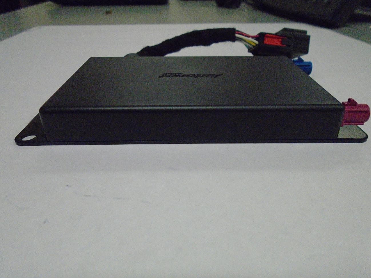
VOI-ANMKNN4RTR-01
May 27, 2015Telematics Control Unit
Equipment Class
DTS - Digital Transmission System
VOI-ANMRHLTCU-01
Mar 17, 2013GPS Tracker
Equipment Class
PCB - PCS Licensed Transmitter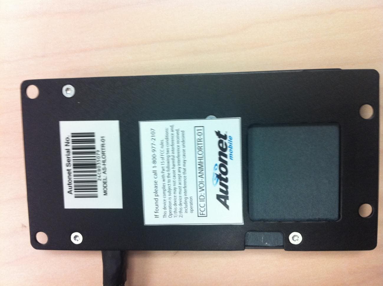
VOI-ANMHLORTR-01
Apr 23, 2012Mobile Router
Equipment Class
PCB - PCS Licensed Transmitter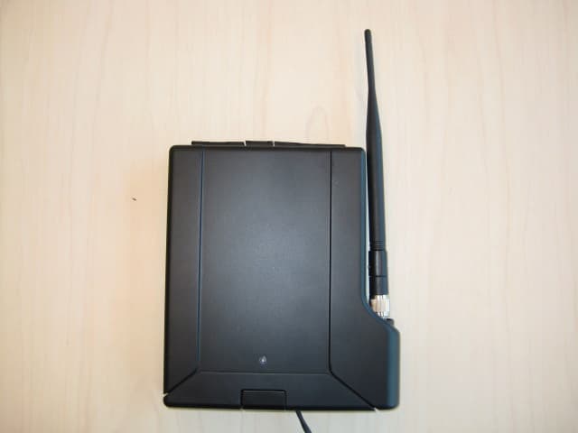
VOI-ANMSTWRTR-02
Oct 18, 2011Mobile Router
Equipment Class
DTS - Digital Transmission System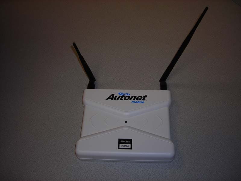
VOI-ANMASPLS-02
Apr 14, 2008Mobile Router
Equipment Class
PCB - PCS Licensed Transmitter