VOI-ANMKNN4RTR-01Telematics Control Unit
Autonet Mobile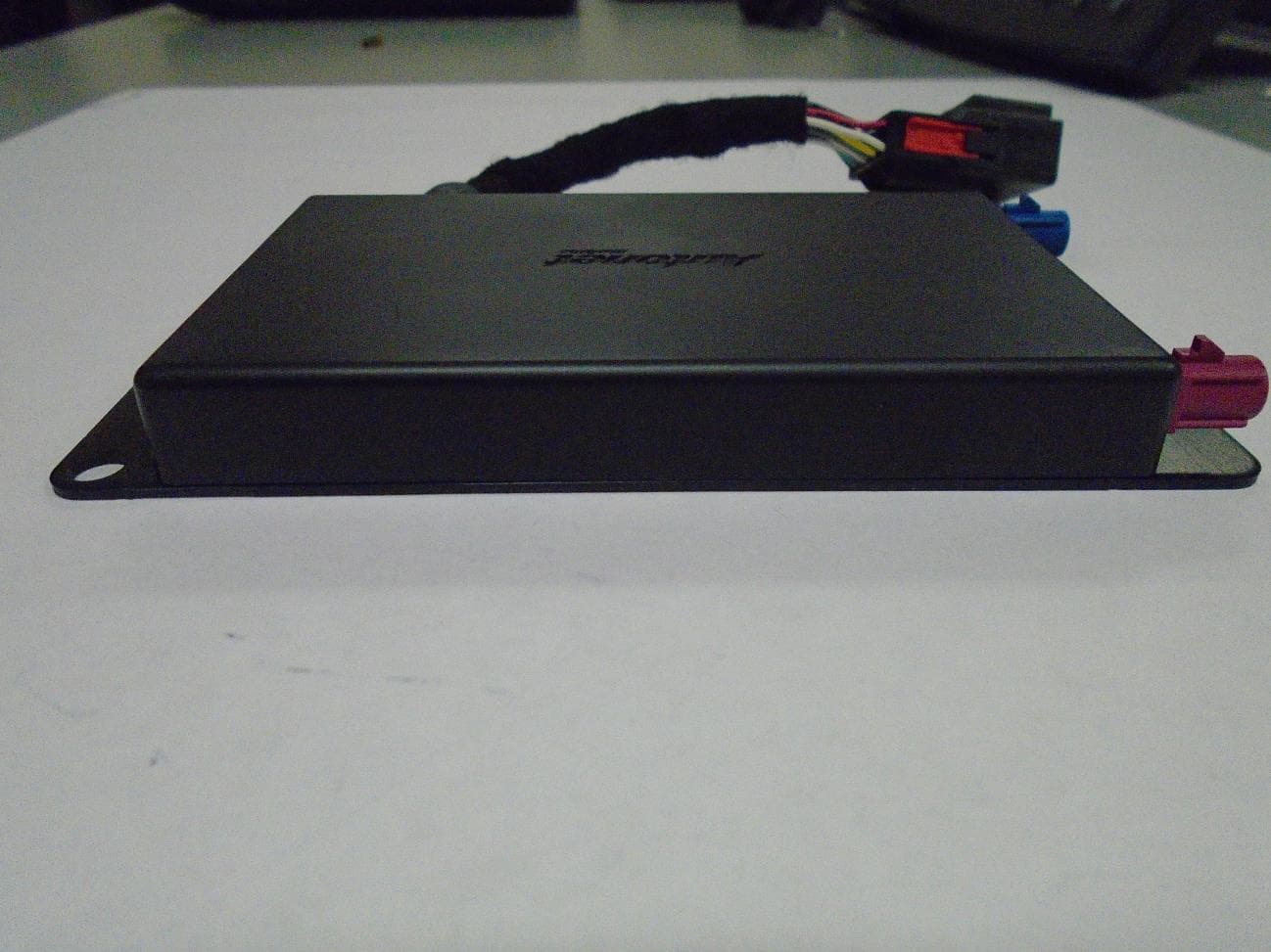
Click to zoom
Application Details
- Equipment Class
- DTS - Digital Transmission System
- Date of Grant
- May 27, 2015
- Application Purpose
- Original Equipment
- Date of Application
- May 27, 2015
- Equipment Note
- Telematics Control Unit
- Frequency Range
- 2412.00000000 - 2462.00000000
- Company
- Autonet Mobile
- Country
- United States
Documents & Files
Document Text
Text extracted from the exhibit documents filed with the FCC. Open a document above to read the original.
Users Manual
Important Product Information GuideAut onet Mobile customer support line: 1-800-977-2107 © 2014 Aut onet Mobile, Inc. P/N: 186-1100-001 Rev. 06 Important Product Information Guide Welcome Quickstart Guide Configuring the In-Car Router Configuring Wireless Settings Configuring Wireless Security Settings Configuring Login Screen Changing the Password on Your In-Car Router Checking the Connection Status of the In-Car Router Troubleshooting Guide Safety Policy Acceptable Use Policy Autonet Mobile Software License Autonet Mobile Limited Warranty and Liability Legal Disclosure 2 4 5 6 9 10 11 12 13 14 20 24 26 27 23 Welcome to Autonet Mobile To activate your account with Autonet Mobile, please submit a completed service agreement online or by fax. Online Go to https://signup.autonetmobile.com Fax Download the service agreement from: https://signup autonetmobile.com and fax the completed agreement to 415-840-1725. If you have any questions please call 1-800-977-2107. For technical support call the Autonet Mobile customer service center: 1-800-977-2107. Autonet Mobile assumes no responsibility for the configurations, security, or data files on your wireless device resulting from connection to Autonet Mobile’s network. Anti-virus, privacy and security protection is the responsibility of the user. Do not operate the In- Car Router while driving or perform any function that takes your attention away from safely driving your vehicle. Any function that requires prolonged attention should be performed after coming to a complete stop. Always stop the vehicle in a safe location before performing these functions. Failure to do so may result in an accident. If the In-Car Router is found, please call: 1-800-977-2107. The router is automatically disabled if lost. 45 Quickstart Guide Step 1 Turn your car to power up Autonet Mobile. Shortly “autonet” will appear in your wireless network list. Step 2 In your wireless network list connect to the wireless network that contains the name “autonet”. Step 3 Open your web browser. Click on the login button. Step 4 Happy surfing! Configuring the In-Car Router It is highly recommended that the user enable WEP security and change the default password on the Autonet Mobile In-Car Router. Configuring the WiFi interface on your In-Car Router The unit’s serial number is is a ten digit hexadecimal number located in 2 places. It is located: 1. On the back of the In-Car Router 2. On the front of the quickstart guide. If you have trouble locating the serial number of the router please call our customer support line at 1-800-977-2107 for assistance. Open a web browser and go to the URL: http://www. autonetrouter.com/admin login as username “autonet” and use the unit’s serial number as the password. (e.g. 0024C76258 ) and click on the “login” button. or 67 Configuring Wireless Settings Click on “Wireless Settings” ESSID Extended Service Set ID. The ESSID is the identifying name of a wireless network - strictly it is the identifying name of a wireless access point. It allows one wireless network to be clearly distinguishable from another. The default ESSID is autonet- XXXX, where XXXX is the last 4 digits of the In-Car Router’s serial number. It is recommended that you keep this ESSID in order to distinguish your router from other routers that may be in the area. WEP key The WEP key is not shown if it is set. You do not have to set it, if you want it to remain the same. To set the current encryption key, just enter the key in hex digits as XXXXXXXXXX. The key must be 10 hex digits, (e.G. 1234567890 ) You can also enter the key as an ASCII string by using the s: prefix. The ASCII string must be five characters, (e.g. s:smile ). To disable WEP, enter “off” as the WEP key. Radio Mode This allows you to select whether the radio is in 802.11b, 802.11g and 802.11a mode. Not all routers support all modes, so only the supported modes for your In-Car Router are shown. Channel Direct communication between an 802.11 Radio card and an access point occurs over a common channel frequency. The FCC allows channels 1 through 11 within the U.S. An important concept to note regarding channel assignments is that the channel actually represents the center frequency that the transceiver within the radio and access point uses (e.g., 2.412 GHz for channel 1 and 2.417 GHz for channel 2). There is only 5 MHz separation between the center frequencies, and an 802.11b signal occupies approximately 30 MHz of the frequency spectrum. The signal falls within about 15 MHz of each side of the center frequency. As a result, an 802.11b signal overlaps with several adjacent channel frequencies. This leaves you with only three channels (channels 1, 6, and 11 for the U.S.) That you can use without causing interference between access points. 89 Bit rate This allows you to set the bit rate in Mbs. The bit rate is the speed at which bits are transmitted over the medium. The user speed of the link is lower due to medium sharing and various overhead. Select a value to lock the card to a particular bit rate. If you specify auto, the driver will use all bit rates to find an optimum rate. RTS threshold RTS/CTS adds a handshake before each packet transmission to make sure that the channel is clear. This adds overhead, but Increases performance in case of hidden nodes or a large number of active nodes. This parameter sets the size of the smallest packet for which the node sends rts; a value equal to the maximum packet size disables the mechanism. You may also set this parameter to off. Fragmentation threshold Fragmentation allows to split an IP packet in a burst of smaller fragments transmitted on the medium. In most cases this adds overhead, but in a very noisy environment this reduces the error penalty and allow packets to get through interference bursts. This parameter sets the maximum fragment size. You may also set this to off to disable the mechanism. TxPower This allows you to set the transmit power of the radio. Setting a…
Text truncated - open the document above for the full version.
Cover Letter(s)
Autonet Mobile, Inc. 1700 Montgomery Ste. 111, San Francisco, CA 94111 Support - 1-800-977-2107 [email protected] www.autonetmobile.com 04/17/2015 MET Laboratories, Inc. 914 West Patapsco Ave. Baltimore, MD 21230 RE: CONFIDENTIALITY REQUEST FOR modem AS-KNNRTR-01 with FCC ID VOI-‐ ANMKNN4RTR-‐01 To Whom it May Concern: This letter serves as an official request under FCC Rule Sections 0.457 & 0.459. We have requested that the schematics, BOM, parts list, block diagram of all component, operational description, tune up procedures and all photos of internal components required to be submitted with this application be withheld from public view. The documents are company proprietary information that could never get into the pocession of our competition. Please contact me if there is any information you need. Sincerely, Doug Moeller Chief Technology Officer
RF Exposure Info
§ 15.247(i) Maximum Permissible Exposure RF Exposure Requirements: §1.1307(b)(1) and §1.1307(b)(2): Systems operating under the provisions of this section shall be operated in a manner that ensures that the public is not exposed to radio frequency energy levels in excess of the Commission’s guidelines. RF Radiation Exposure Limit: §1.1310: As specified in this section, the Maximum Permissible Exposure (MPE) Limit shall be used to evaluate the environmental impact of human exposure to radiofrequency (RF) radiation as specified in Sec. 1.1307(b), except in the case of portable devices which shall be evaluated according to the provisions of Sec. 2.1093 of this chapter. MPE Limit Calculation: EUT’s operating frequencies @ 2400-2483.5 MHz; highest conducted power = 15.69 dBm (peak) therefore, Limit for Uncontrolled exposure: 1 mW/cm 2 or 10 W/m 2 EUT maximum antenna gain = 1.88 dBi. Equation from page 18 of OET 65, Edition 97-01 S = PG / 4R 2 or R = √PG / 4S where, S = Power Density (1 mW/cm 2 ) P = Power Input to antenna (37.068mW) G = Antenna Gain (1.542 numeric) R = Minimum Distance between User and Antenna (20 cm) S = (37.068*1.542)/(4*3.14*20 2 ) = 57.159/5024 = 0.011 mW/cm 2 Since S < 1 mW/cm 2 , the minimum distance (R) is 20cm
Test Report
MET Laboratories, Inc. Safety Certification - EMI - Telecom Environmental Simulation 914 WEST PATAPSCO AVENUE ! BALTIMORE, MARYLAND 21230-3432 ! PHONE (410) 354-3300 ! FAX (410) 354-3313 33439 WESTERN AVENUE ● UNION CITY, CALIFORNIA 94587 ● PHONE (510) 489-6300 ● FAX (510) 489-6372 3162 BELICK STREET ● SANTA CLARA, CALIFORNIA 95054 ● PHONE (408 748-3585 ● FAX (510) 489-6372 The Nation’s First Licensed Nationally Recognized Testing Laboratory May 13, 2015 Autonet Mobile 1700 Montgomery Suite 111 San Francisco, CA 94111 Dear Doug Moeller, Enclosed is the EMC Wireless test report for compliance testing of the Autonet Mobile, Kanaan4 as tested to the requirements of Title 47 of the CFR, Ch. 1 (10-1-06 ed.), Part 15, Subpart B for a Class B Digital Device and FCC Part 15 Subpart C for Intentional Radiators. Thank you for using the services of MET Laboratories, Inc. If you have any questions regarding these results or if MET can be of further service to you, please feel free to contact me. Sincerely yours, MET LABORATORIES, INC. Jennifer Warnell Documentation Department Reference: (\Autonet Mobile\EMCS42581A-FCC247 Rev. 1) Certificates and reports shall not be reproduced except in full, without the written permission of MET Laboratories, Inc. Electromagnetic Compatibility Autonet Mobile Cover Page Kanaan4 CFR Title 47, Part 15B, 15.247 MET Report: EMCS42581A-FCC247 Rev. 1 © 2015, MET Laboratories, Inc. Page ii of viii DOC-EMC702 6/18/2009 Electromagnetic Compatibility Criteria Test Report for the Autonet Mobile Kanaan4 Tested under the FCC Certification Rules contained in Title 47 of the CFR, Parts 15 Subpart B for Class B Digital Devices & 15.247 Subpart C for Intentional Radiators MET Report: EMCS42581A-FCC247 Rev. 1 May 13, 2015 Prepared For: Autonet Mobile 1700 Montgomery Suite 111 San Francisco, CA 94111 Prepared By: MET Laboratories, Inc. 3162 Belick St. Santa Clara, CA 95054 Electromagnetic Compatibility Autonet Mobile Cover Page Kanaan4 CFR Title 47, Part 15B, 15.247 MET Report: EMCS42581A-FCC247 Rev. 1 © 2015, MET Laboratories, Inc. Page iii of viii DOC-EMC702 6/18/2009 Electromagnetic Compatibility Criteria Test Report for the Autonet Mobile Kanaan4 Tested under the FCC Certification Rules contained in Title 47 of the CFR, Parts 15 Subpart B for Class B Digital Devices & 15.247 Subpart C for Intentional Radiators Ajaz Khan, Project Engineer Jennifer Warnell Electromagnetic Compatibility Lab Documentation Department Engineering Statement: The measurements shown in this report were made in accordance with the procedures indicated, and the emissions from this equipment were found to be within the limits applicable. I assume full responsibility for the accuracy and completeness of these measurements, and for the qualifications of all persons taking them. It is further stated that upon the basis of the measurements made, the equipment tested is capable of operation in accordance with the requirements of the FCC Rules Parts 15B, 15.247 under normal use and maintenance. Asad Bajwa, Director, Electromagnetic Compatibility Lab Electromagnetic Compatibility Autonet Mobile Report Status Kanaan4 CFR Title 47, Part 15B, 15.247 MET Report: EMCS42581A-FCC247 Rev. 1 © 2015, MET Laboratories, Inc. Page iv of viii DOC-EMC702 6/18/2009 Report Status Sheet Revision Report Date Reason for Revision April 29, 2015 Initial Issue. 1 May 13, 2015 Engineer corrections. Electromagnetic Compatibility Autonet Mobile Table of Contents Kanaan4 CFR Title 47, Part 15B, 15.247 MET Report: EMCS42581A-FCC247 Rev. 1 © 2015, MET Laboratories, Inc. Page v of viii DOC-EMC702 6/18/2009 Table of Contents I. Executive Summary .................................................................................................................................................1 A. Purpose of Test ...................................................................................................................................................2 B. Executive Summary ............................................................................................................................................2 II. Equipment Configuration .......................................................................................................................................3 A. Overview .............................................................................................................................................................4 B. References ...........................................................................................................................................................5 C. Test Site ..............................................................................................................................................................5 D. Description of Test Sample .................................................................................................................................6 E. Equipment Configuration ....................................................................................................................................7 F. Ports and Cabling Information ............................................................................................................................7 G. Mode of Operation ..............................................................................................................................................7 H. Monitoring Method .............................................................................................................................................7 I. Modifications ......................................................................................................................................................7 a) Modifications to EUT .................................................................................................................... 7 b) Modifications to Test Standard...............................…
Text truncated - open the document above for the full version.
Test Setup Photos
Photograph 1. Radiated Emissions, Test Setup, 30 MHz – 1 GHz Photograph 2. Radiated Spurious Emissions, 30 MHz – 18 GHz, Test Setup Photograph 3. Radiated Spurious Emissions, 1 GHz – 18 GHz, Test Setup
Contact Information
Applicant
Doug Moeller(CTO)
Technical Contact
Autonet MobileDoug Moeller
[email protected]415-223-0316
3636 N. Laughlin #150 · Santa Rosa, California · United States
Test Firm
EUROFINS ELECTRICAL AND ELECTRONIC TESTING NA, INCGreg Kovolenko
Technical Specifications
| # | Rule Parts | Frequency Range | Power Output |
|---|---|---|---|
| 1 | 15C | 2.41 GHz - 2.46 GHz | 37.00 mW |
Other Applications from Autonet Mobile
VOI-ANMKNN3RTR-01
Aug 18, 2014Mobile Router
Equipment Class
DSS - Part 15 Spread Spectrum Transmitter
VOI-ANMRHLTCU-01
Mar 17, 2013GPS Tracker
Equipment Class
PCB - PCS Licensed Transmitter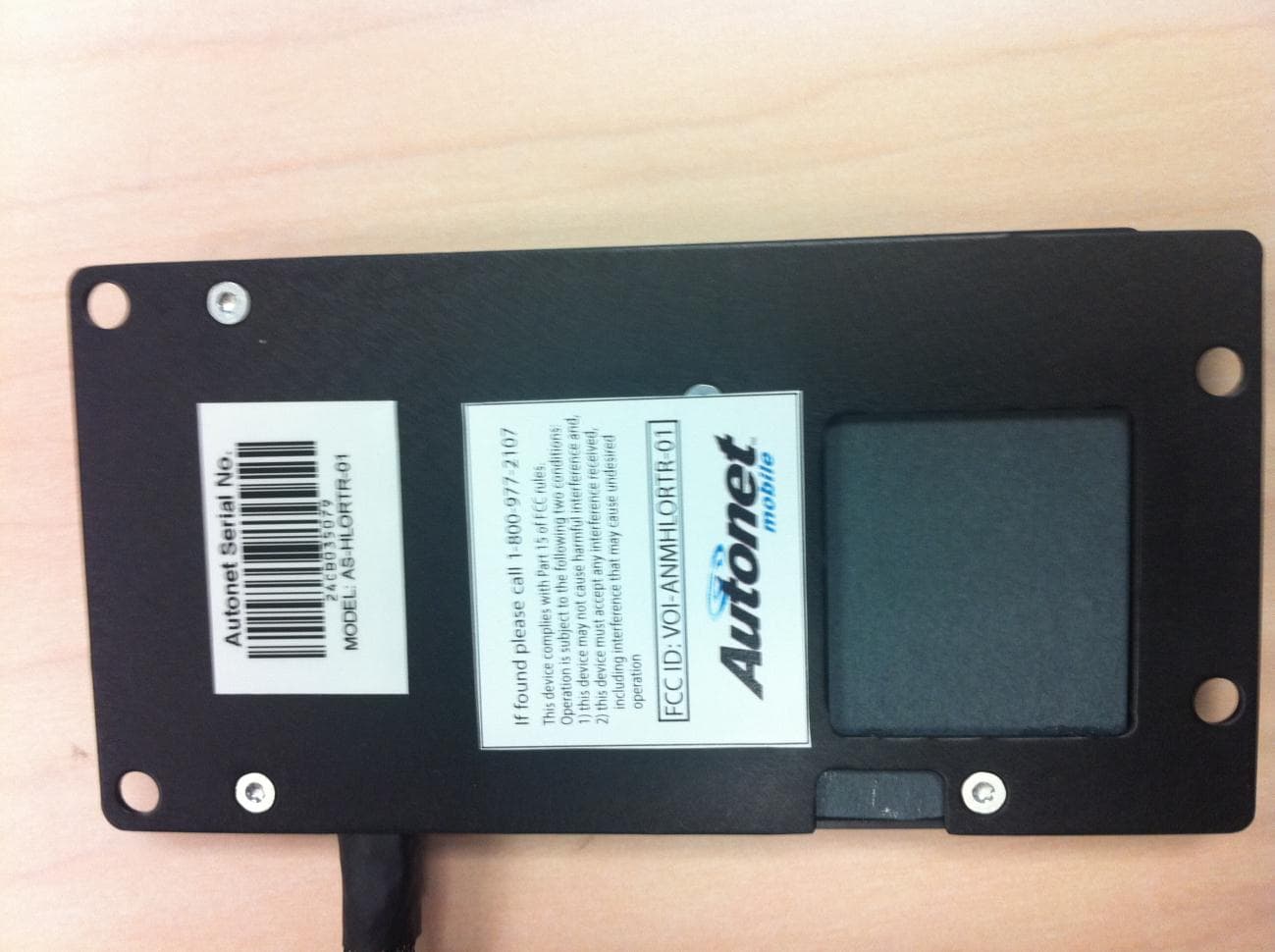
VOI-ANMHLORTR-01
Apr 23, 2012Mobile Router
Equipment Class
PCB - PCS Licensed Transmitter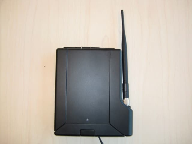
VOI-ANMSTWRTR-02
Oct 18, 2011Mobile Router
Equipment Class
DTS - Digital Transmission System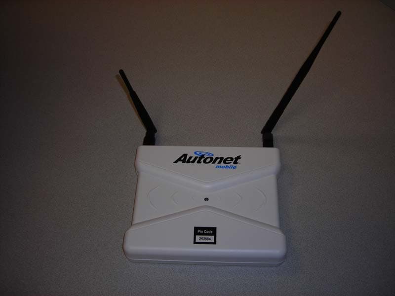
VOI-ANMASPLS-02
Apr 14, 2008Mobile Router
Equipment Class
PCB - PCS Licensed Transmitter