VTV-RFBHNBluetooth module
TSC Auto ID Technology Co., Ltd.
Click to zoom
Application Details
- Equipment Class
- DTS - Digital Transmission System
- Date of Grant
- Jan 04, 2024
- Application Purpose
- Original Equipment
- Date of Application
- Jan 03, 2024
- Equipment Note
- Bluetooth module
- Frequency Range
- 2402.00000000 - 2480.00000000
- Country
- Taiwan
Documents & Files
Document Text
Text extracted from the exhibit documents filed with the FCC. Open a document above to read the original.
Users Manual
TSC USER’S MANUAL RF-BHN , RF-BHS Bluetooth module Copyright Information © 2014 TSC Auto ID Technology Co., Ltd, The copyright in this manual, the software and firmware in the printer described therein are owned by TSC Auto ID Technology Co., Ltd, All rights reserved. Information in this document is subject to change without notice and does not represent a commitment on the part of TSC Auto ID Technology Co. No part of this manual may be reproduced or transmitted in any form or by any means, for any purpose other than the purchaser’s personal use, without the expressed written permission of TSC Auto ID Technology Co. Agency Compliance and Approvals Federal Communication Commission Interference Statement This equipment has been tested and found to comply with the limits for a Class B digital device, pursuant to Part 15 of the FCC Rules. These limits are designed to provide reasonable protection against harmful interference in a residential installation. This equipment generates, uses and can radiate radio frequency energy and, if not installed and used in accordance with the instructions, may cause harmful interference to radio communications. However, there is no guarantee that interference will not occur in a particular installation. If this equipment does cause harmful interference to radio or television reception, which can be determined by turning the equipment off and on, the user is encouraged to try to correct the interference by one of the following measures: - Reorient or relocate the receiving antenna. - Increase the separation between the equipment and receiver. - Connect the equipment into an outlet on a circuit different from that to which the receiver is connected. - Consult the dealer or an experienced radio/TV technician for help. FCC Caution: Any changes or modifications not expressly approved by the party responsible for compliance could void the user's authority to operate this equipment. This device complies with Part 15 of the FCC Rules. Operation is subject to the following two conditions: (1) This device may not cause harmful interference, and (2) this device must accept any interference received, including interference that may cause undesired operation. IMPORTANT NOTE: FCC Radiation Exposure Statement: The product comply with the US portable RF exposure limit set forth for an uncontrolled environment and are safe for intended operation as described in this manual. The further RF exposure reduction can be achieved if the product can be kept as far as possible from the user body or set the device to lower output power if such function is available. This transmitter must not be co-located or operating in conjunction with any other antenna or transmitter. This module is intended for OEM integrators only. Per FCC KDB 996369 D03 OEM Manual v01 guidance, the following conditions must be strictly followed when using this certified module: KDB 996369 D03 OEM Manual v01 rule sections: 2.2 List of applicable FCC rules This module has been tested for compliance to FCC Part 15 Subpart C (15.247). 2.3 Specific operational use conditions This module is stand-alone modular. If the end product will involve the Multiple simultaneously transmitting condition or different operational conditions for a stand-alone modular transmitter in a host, host manufacturer have to consult with module manufacturer for the installation method in end system. 2.4 Limited module procedures Not applicable. 2.5 Trace antenna designs Not applicable. 2.6 RF exposure considerations This equipment complies with FCC radiation exposure limits set forth for an uncontrolled environment. This equipment should be installed and operated with a minimum distance of 20 cm between the radiator & your body. 2.7 Antennas This radio transmitter has been approved by Federal Communications Commission to operate with the antenna types listed below, with the maximum permissible gain indicated. Antenna types not included in this list that have a gain greater than the maximum gain indicated for any type listed are strictly prohibited for use with this device. Ant. Brand Part Number Type Frequency Range (MHz) Gain (dBi) 1. TSC AT9520-B2R4HAAT/LF Chip Antenna 2400-2500 3.0 2.8 Label and compliance information The final end product must be labeled in a visible area with the following: “Contains FCC ID: VTV-RFBHN”. The grantee's FCC ID can be used only when all FCC compliance requirements are met. 2.9 Information on test modes and additional testing requirements Host manufacturer is strongly recommended to confirm compliance with FCC requirements for the transmitter when the module is installed in the host. 2.10 Additional testing, Part 15 Subpart B disclaimer Host manufacturer is responsible for compliance of the host system with module installed with all other applicable requirements for the system such as Part 15 B. 2.11 Note EMI Considerations Host manufacture is recommended to use D04 Module Integration Guide recommending as "best practice" RF design engineering testing and evaluation in case non-linear interactions generate additional non-compliant limits due to module placement to host components or properties. 2.12 How to make changes This module is stand-alone modular. If the end product will involve the Multiple simultaneously transmitting condition or different operational conditions for a stand-alone modular transmitter in a host, host manufacturer have to consult with module manufacturer for the installation method in end system. According to the KDB 996369 D02 Q&A Q12, that a host manufacture only needs to do an evaluation (i.e., no C2PC required when no emission exceeds the limit of any individual device (including unintentional radiators) as a composite. The host manufacturer must fix any failure. Industry Canada statement: This device complies with Industry Canada’s licence-exempt RSSs. Operation is subject to the following two conditions: (1) This device may not cause interference; and (2) This device must accep…
Text truncated - open the document above for the full version.
Attestation Statements
TSC Auto ID Technology Co., Ltd. Federal Communications Commission Authorization and Evaluation Division 7435 Oakland Mills Road Columbia, MD 21046 USA Date: 12-27-2023 Ref: Attestation Statements Part 2.911(d)(7) Filing FCC ID: VTV-RFBHN TSC Auto ID Technology Co., Ltd. (“the applicant”) certifies that, as of the date of the filing of the application, TianHeng Consulting, LLC. is our designated U.S. agent for service of process for the above referenced FCC ID. TSC Auto ID Technology Co., Ltd. accepts to maintain an agent for no less than one year after the grantee has terminated all marketing and importation or the conclusion of any Commission-related proceeding involving the equipment. TianHeng Consulting, LLC. accepts, as of the date of the filing of the application, the obligation of the designated U.S. agent for service of process for the above referenced FCC ID. Sincerely, Designated U.S. Agent Information: Name: TianHeng Consulting, LLC. FRN: 0033401258 Contact Person: Hualing Dong Address: 392 Andover Street, Wilmington, MA 01887, United States Tel.: +1 617-997-4010 Email: [email protected] U.S. Agent Signature: Applicant: Company Name: TSC Auto ID Technology Co., Ltd. Grantee Code: VTV Contact Name: Roger Wu Address: 9F., No. 95, Minquan Rd. Xindian Dist., New Taipei City, Taiwan Tel.: +886-3-990-6677 Ext. 5307 Email: [email protected] Applicant Signature: Hualing Dong, President
Attestation Statements
TSC Auto ID Technology Co., Ltd. Certification Application Attestation Statements TSC Auto ID Technology Co., Ltd. 9F., No. 95, Minquan Rd. Xindian Dist. New Taipei City 23141, Taiwan Subject: FCC ID: VTV-RFBHN To Whom It May Concern: Statement for 47 CFR section 2.911(d)(5)(i) TSC Auto ID Technology Co., Ltd. certifies that as of the date of the application the equipment for which authorization is sought is not “covered” equipment 1 prohibited from receiving an equipment authorization pursuant to section 2.903 of the FCC rules. If the equipment for which the applicant seeks authorization is produced by any of the entities identified on the current Covered List, including affiliates or subsidiaries of the named companies, the applicant must include an explanation on why the equipment is not “covered” equipment. Additional Explanation: <N/A> Statement for 47 CFR section 2.911(d)(5)(ii) TSC Auto ID Technology Co., Ltd. (“the applicant”) certifies that, as of the date of the filing of this application, the applicant - is / - is not (3) identified on the Covered List as an entity producing “covered” equipment. Date: 2023-12-26 City: New Taipei City Name (2) : Roger Wu Telephone number: +886-3-990-6677 Ext. 5307 Email address: [email protected] Signature: 1 - The Commission’s Covered List is published by the Public Safety and Homeland Security Bureau and posted on the Commission’s website. This Covered List, which is periodically updated, identifies particular equipment, produced by particular entities, that constitutes “covered” equipment. https://www.fcc.gov/supplychain/coveredlist . (2): For FCC it must be the Grantee Code “owner” or the authorized agent. (3): double click on the appropriate box and select ‘’checked” then “OK”
Cover Letter(s)
TSC Auto ID Technology Co., Ltd. DECLARATION OF AUTHORISATION Hereby, we Name: TSC Auto ID Technology Co., Ltd. Address: 9F., No. 95, Minquan Rd. Xindian Dist., New Taipei City, Taiwan Declare that: Name of Representative of Agent: Kent Liu Agent Company name: BTL Inc. Address: 4F.,No.18, Ln. 171, Sec. 2, Jiuzong Rd., Neihu Dist., Taipei City 114, Taiwan is authorized to apply for Certification and signing related documents of the following product(s), including application form(s): FCC ID: VTV-RFBHN IC: 10524A-RFBHN Validity/Expiry Date: 2024-12-20 Signature: Date: 2023-12-26 City: New Taipei City Name: Roger Wu Telephone: +886-3-990-6677 Ext. 5307 E-mail: [email protected]
Cover Letter(s)
TSC Auto ID Technology Co., Ltd. Company Name: TSC Auto ID Technology Co., Ltd. Address: 9F., No. 95, Minquan Rd. Xindian Dist. City: New Taipei City Country: Taiwan To: Kiwa Netherlands B.V., Dept. FCC TCB Wilmersdorf 50 7327 AC Apeldoorn The Netherlands Subject: Request for confidentiality FCC ID: VTV-RFBHN Reference number: ###### Dear FCC TCB, 1. Long-Term Confidentiality Pursuant to 47 CFR Section 0.459(a) & (b), we hereby requests non-disclosure and confidential treatment of the following materials submitted in support of FCC certification application: Bill(s) of Material Block Diagrams Operational Description Schematic Diagrams Tune-up Procedure Above materials contain secrets, proprietary and technical information, which would customarily be guarded from competitors under 47 CFR, section 0.457(d)(2). Disclosure or publication or any portion of this company confidential material to other parties could cause substantial competitive harm and provide unjustified benefits for competitors. 2. Short-Term Confidentiality (STC) Pursuant to Public Notice DA 04-1705 of the Commission’s policy, in order to comply with the marketing regulations in 47 CFR §2.803 and the importation rules in 47 CFR §2.1204, applicant hereby requests Short-Term Confidential treatment of the following materials (See notes below): Internal Photos User’s Manual Test Set-up Photos External Photos Justification: Date: 2023-12-26 Name and signature of applicant: Roger Wu Notes: 1) A document or type of document can only have ONE type of confidentiality! 2) Short-Term confidentiality is in principle for 45 days from date of grant; it can be extended max 3 times (total time 180 days max.)! The planned date should state in the RF731 application form. 3) FCC must be informed when marketing begins earlier. 4) Release takes place automatically thus extension must be requested in time. Telefication does not remind you of this! 5) Request for extension or for release must be received by Kiwa NL B.V. at least 7 days before date of actual marketing or before expiration of the STC period\
Cover Letter(s)
TSC Auto ID Technology Co., Ltd. Modular Approval Request FCC (KDB 996369 D01 & Part 15.212) FCC ID: VTV-RFBHN Items to be covered by Single modular transmitters. Answer from applicant 1. The radio elements must have the radio frequency circuitry shielded. Physical components and tuning capacitor(s) may be located external to the shield, but must be on the module assembly. Yes, the modular has own shielding cover. . 2. The module must have buffered modulation/data inputs to ensure that the device will comply with Part 15 requirements with any type of input signal. The modular transmitter have buffered modulation/data inputs. 3. The module must contain power supply regulation on the module The modular transmitter have its own power supply regulation. 4. The module must contain a permanently attached antenna, or contain a unique antenna connector, and be marketed and operated only with specific antenna(s), per §§ 15.203, 15.204(b), 15.204(c), 15.212(a), 2.929(b). The modular transmitter complies with the antenna requirements of Section 15.203 and 15.204(c). The antenna either be permanently attached. 5.The module must demonstrate compliance in a stand-alone configuration. The module can be configured independently and meets the requirements. 6.The module must be labeled with its permanently affixed FCC ID label, or use an electronic display (see KDB Publication 784748). The FCC ID on the product: VTVFSCBT826HC . 7.The module must comply with all specific rules applicable to the transmitter, including all the conditions provided in the integration instructions by the grantee. YES, please refer to the user manual. 8.The module must comply with RF exposure requirements. YES, RF exposure statement is attached in the user manual. TSC Auto ID Technology Co., Ltd. Items to be covered by Split modular transmitters. Answer from applicant 1. The modular transmitter must comply with all requirements of a single modular transmitter except for items (1) & (5) of the above single modular approval requirements. N/A 2. Only the radio front end must be shielded. The physical crystal and tuning capacitors may be located external to the shielded radio elements. The interface between the split sections of the modular system must be digital with a minimum signalling amplitude of 150 mV peak-to-peak. N/A 3. Control information and other data may be exchanged between the transmitter control elements and radio front end. N/A 4. The sections of a split modular transmitter must be tested installed in a host device(s) similar to that which is representative of the platform(s) intended for use. N/A 5. Manufacturers must ensure that only transmitter control elements and radio front end components that have been approved together are capable of operating together. The transmitter module must not operate unless it has verified that the installed transmitter control elements and radio front end have been authorized together. Manufacturers may use means including, but not limited to, coding in hardware and electronic signatures in software to meet these requirements, and must describe the methods in their application for equipment authorization. N/A Note: A limited modular approval (LMA) may be granted for single or split modular transmitters that comply partially with the requirements above. Name and surname of applicant (or authorized representative): Roger Wu Date: 2023-12-26 Signature:
External Photos
Appendix No.: EP-2311T049-1 APPENDIX-EUT PHOTOS Project No.: 2311T049 Page 1 of 8 Appendix No.: EP-2311T049-1 APPENDIX-EUT PHOTOS Project No.: 2311T049 Page 2 of 8 Appendix No.: EP-2311T049-1 APPENDIX-EUT PHOTOS Project No.: 2311T049 Page 3 of 8 Appendix No.: EP-2311T049-1 APPENDIX-EUT PHOTOS Project No.: 2311T049 Page 4 of 8
ID Label/Location Info
Label Sample Label Location Label
Internal Photos
Appendix No.: EP-2311T049-1 APPENDIX-EUT PHOTOS Project No.: 2311T049 Page 5 of 8 Appendix No.: EP-2311T049-1 APPENDIX-EUT PHOTOS Project No.: 2311T049 Page 6 of 8 Appendix No.: EP-2311T049-1 APPENDIX-EUT PHOTOS Project No.: 2311T049 Page 7 of 8 Appendix No.: EP-2311T049-1 APPENDIX-EUT PHOTOS Project No.: 2311T049 Page 8 of 8
RF Exposure Info
Report No.: BTL-FCCP-3-2311T049 Project No.: 2311T049 Page 1 of 8 Report Version: R01 FCC RF Exposure Report FCC ID: VTV-RFBHN Report No. : BTL-FCCP-3-2311T049 Equipment : Bluetooth module Model Name : RF-BHS, RF-BHN Brand Name : TSC Applicant : TSC Auto ID Technology Co., Ltd. Address : 9F., No. 95, Minquan Rd. Xindian Dist. New Taipei Standard(s) : 47 CFR § 2.1091 FCC Guidelines for Human Exposure IEEE C95.1 Date of Receipt : 2023/11/21 Date of Test : 2023/12/1 ~ 2023/12/6 Issued Date : 2023/12/27 The above equipment has been tested and found in compliance with the requirement of the above standards by BTL Inc. Prepared by : Jerry Chuang, Supervisor Approved by : Peter Chen, Manager BTL Inc. No.18, Ln. 171, Sec. 2, Jiuzong Rd., Neihu Dist., Taipei City 114, Taiwan Tel: +886-2-2657-3299 Fax: +886-2-2657-3331 Web: www.newbtl.com Service mail: [email protected] Report No.: BTL-FCCP-3-2311T049 Project No.: 2311T049 Page 2 of 8 Report Version: R01 Declaration BTL represents to the client that testing is done in accordance with standard procedures as applicable and that test instruments used has been calibrated with standards traceable to international standard(s) and/or national standard(s). BTL's reports apply only to the specific samples tested under conditions. It is manufacture’s responsibility to ensure that additional production units of this model are manufactured with the identical electrical and mechanical components. BTL shall have no liability for any declarations, inferences or generalizations drawn by the client or others from BTL issued reports. This report is the confidential property of the client. As a mutual protection to the clients, the public and ourselves, the test report shall not be reproduced, except in full, without our written approval. BTL’s laboratory quality assurance procedures are in compliance with the ISO/IEC 17025 requirements, and accredited by the conformity assessment authorities listed in this test report. BTL is not responsible for the sampling stage, so the results only apply to the sample as received. The information, data and test plan are provided by manufacturer which may affect the validity of results, so it is manufacturer’s responsibility to ensure that the apparatus meets the essential requirements of applied standards and in all the possible configurations as representative of its intended use. Limitation For the use of the authority's logo is limited unless the Test Standard(s)/Scope(s)/Item(s) mentioned in this test report is (are) included in the conformity assessment authorities acceptance respective. Please note that the measurement uncertainty is provided for informational purpose only and are not use in determining the Pass/Fail results. Report No.: BTL-FCCP-3-2311T049 Project No.: 2311T049 Page 3 of 8 Report Version: R01 REVISION HISTORY Report No. Version Description Issued Date Note BTL-FCCP-3-2311T049 R00 Original Report. 2023/12/21 Invalid BTL-FCCP-3-2311T049 R01 Revise Typo. 2023/12/27 Valid Report No.: BTL-FCCP-3-2311T049 Project No.: 2311T049 Page 4 of 8 Report Version: R01 1. LIMITS According to § 1.1310 Radiofrequency radiation exposure limits. (a) Specific absorption rate (SAR) shall be used to evaluate the environmental impact of human exposure to radiofrequency (RF) radiation as specified in § 1.1307(b) of this part within the frequency range of 100 kHz to 6 GHz (inclusive). (b) The SAR limits for occupational/controlled exposure are 0.4 W/kg, as averaged over the whole body, and a peak spatial-average SAR of 8 W/kg, averaged over any 1 gram of tissue (defined as a tissue volume in the shape of a cube). Exceptions are the parts of the human body treated as extremities, such as hands, wrists, feet, ankles, and pinnae, where the peak spatial-average SAR limit for occupational/controlled exposure is 20 W/kg, averaged over any 10 grams of tissue (defined as a tissue volume in the shape of a cube). Exposure may be averaged over a time period not to exceed 6 minutes to determine compliance with occupational/controlled SAR limits. (c) The SAR limits for general population/uncontrolled exposure are 0.08 W/kg, as averaged over the whole body, and a peak spatial-average SAR of 1.6 W/kg, averaged over any 1 gram of tissue (defined as a tissue volume in the shape of a cube). Exceptions are the parts of the human body treated as extremities, such as hands, wrists, feet, ankles, and pinnae, where the peak spatial-average SAR limit is 4 W/kg, averaged over any 10 grams of tissue (defined as a tissue volume in the shape of a cube). Exposure may be averaged over a time period not to exceed 30 minutes to determine compliance with general population/uncontrolled SAR limits. (e) Limits for Maximum Permissible Exposure (MPE) to radiofrequency electromagnetic fields (Table 1). Frequency range (MHz) Electric field strength (V/m) Magnetic field strength (A/m) Power density (mW/cm 2 ) Averaging time (minutes) (i) Limits for Occupational/Controlled Exposure 0.3-3.0 614 1.63 *(100) ≤6 3.0-30 1842/f 4.89/f *(900/f 2 ) <6 30-300 61.4 0.163 1.0 <6 300-1.500 f/300 <6 1.500-100.000 5 <6 (ii) Limits for General Population/Uncontrolled Exposure 0.3-1.34 614 1.63 *(100) <30 1.34-30 824/f 2.19/f *(180/f 2 ) <30 30-300 27.5 0.073 0.2 <30 300-1.500 f/1500 <30 1.500-100.000 1.0 <30 f = frequency in MHz. * = Plane-wave equivalent power density. Report No.: BTL-FCCP-3-2311T049 Project No.: 2311T049 Page 5 of 8 Report Version: R01 2. APPLIED EXEMPTION CRITERIA Refer to KDB 447498 D04, ticked item is applied: For RF Exposure Test Exemptions for Single Source: ☐ 1-mW Test Exemption Per § 1.1307(b)(3)(i)(A), a single RF source is exempt RF device (from the requirement to show data demonstrating compliance to RF exposure limits, as previously mentioned) if the available maximum time-averaged power is no more than 1 mW, regardless of separation distance. This exemption applies to all operating configurations and exposure conditions, for the frequency range 100 kHz to …
Text truncated - open the document above for the full version.
Test Report
鼎 翰 科 技 股 份 有 限 公 司 產品規格書 暨 樣品承認書 1. 產品規格書編號:60-0480003-10LF 2. 品名:Chip Antenna/ SMD天線 AT9520-B2R4HAAT/LF(嘉光) 3. 產品規格書與樣品承認書履歷: 版次 修 訂 履 歷 ECO或ECN編號 生效日期 樣 品 料 號 A 新訂 2015.11.12 60-0480003-10LF 4. 已承認樣品清冊: 項 次 樣品料號 版次 製造商 /供應商 承認日期 承認型式 舊樣品處理 限量 正式 留用 廢止 1 60-0480003-10LF A 嘉光 2015.07.17 V ******** 本文件之著作權及營業機密內容屬於鼎翰科技,非經許可不得翻印 *******﹝104406K﹞ ኬࠔဦ ހᜪձ ቷӜᆀࠔӜೕଌኬВය ԛԛᇙж 160-0480003-10LFAɎӀࣽިמҽԖ ज़Ϧљ)Ӏࣽ *מ Chip Antenna/ SMDϺ ጕ!AT9520- B2R4HAAT/LF(Ӏ* 2015/07/14 2/!ኬ܍ࠔᇡෳ၂ҞǺ A.dz௦ᖼǺ)ਜय़ၗሡԄ3ҽϷኬ3ࠔҽǶኧໆࠔኬܴќԖᇥߚନǺ* A.1 ଌኬҞޑǺɎཥ໒วdzɍᡂdzɍཥቷdzɍቷᡂdzഢຏǺ A.2 ೕၗǺ)ፎϭᒧ* ɍೕਜdzdzdzdzɍٮᔈෳ၂ൔdzdzdzdzdzɍՅьdz ɍ፦ܴdzdzdzɍٮᔈё܄ෳ၂ൔdzdzɎቷӼೕਜdz Ɏቷ܍ᇡਜdzdzɍдځdzഢຏǺ B.dzπําǺ B.1 ٬ҔᐒᅿǺ ɍӈسӄɎᐒᅿ:MFi BT module for T048 T052 B.2 ኬࠔෳ၂Ǻ ɍխᡍɎӝɍόӝǴံкᇥܴ; B.3 ೕዴᇡǺ Ɏ಄ӝɍό಄ӝɍሡံк: B.4 ፦ᇡёǺ ɎխᡍɍӝɍόӝǴ፦ᅿᜪᇥܴ; B.5 ӼೕᇡёǺ ɍόሡाɎӝɍሡख़ෳǴӼೕᅿᜪᇥܴ; B.6 ኳڀᇡёǺ ɎόሡाɍӝɍόӝǴኳڀᅿᜪᇥܴ; B.7 ᇙբڀݯǺ ɎڀݯόሡɍڀݯሡǴ;ܴᅿᜪᇥڀݯ B.8 ᔠᡍख़ᗺǺ ɎόሡाɍሡҢǴҢᇥܴ; B.9 ᇡё่݀Ǻ ɎϢԏɍԏܔǴံкᇥܴ; ޣගਢǺ൛!3126018025ഋ٩ᠵ!3126018025 ޣᇡёǺՖεҺ!3126018028 C.dzൂՏߥࠔǺ C.1 ኬࠔෳ၂Ǻ ɎխᡍɍӝɍόӝǴံкᇥܴ; C.2 ტڮෳ၂Ǻ ɎխᡍɍӝɍόӝǴံкᇥܴ; ޣᇡёǺશ၃!3126021026 ++++++++!ኬ܍ࠔᇡਜ!++++++++ ++++++¡ҁЎҹβբϷᔼᐒஏϣឦܭႳᑣࣽמǴߚёόளᙌӑ!+++++![104406K] Ⴓ!ᑣ!ࣽ!!ި!מҽ!Ԗ!ज़!Ϧ!љ D.dzࠔᆅൂՏǺ D.1 ೕዴᇡǺ Ɏ಄ӝɍό಄ӝɍሡံк: D.2 ӼೕᇡёǺ Ɏόሡाɍ಄ӝɍό಄ӝǴӼೕᅿᜪᇥܴ; D.3 ᔠᡍख़ᗺǺɍόሡाɎςҢɍሡख़ཥҢǴҢᇥܴ; D.4 RoHSᔠෳǺɎϢԏɍԏܔǴံкᇥܴ; D.5 ᇡё่݀ǺɎϢԏɍԏܔǴံкᇥܴ; ޣᇡёǺඳܲξ!3126022021ֆ܍ᑣ!3126022016 3/!ౢࠔೕਜᆶኬ܍ࠔᇡਜวՉइᒵǺ A.dzπําǺ A.1 ೕਜހձዴᇡǺ ԛހঅुቬᐕECO !܈ECN ጓဦғਏВයኬࠔဦ Aཥुˇˇˇˇ2015/11/1260-0480003-10LF A.2 ኬހࠔҁዴᇡᆶᙑኬࠔೀǺ ኬࠔဦԛހ ᇙ܍ᇡВයᙑኬࠔೀ ԛ0ٮᔈ੮ҔቲЗ 160-0480003-10LFA ӀࣽިמҽԖ ज़Ϧљ 2015/07/17Ɏ A.3 ၸයኬࠔӣԏǺɎࣴวπําdzɍߥࠔdzɍᔈٮdzɍдځdz ޣᇡёǺ݅ᓄ!3126022023 ++++++¡ҁЎҹβբϷᔼᐒஏϣឦܭႳᑣࣽמǴߚёόளᙌӑ!+++++![104406K] Ⴓ!ᑣ!ࣽ!!ި!מҽ!Ԗ!ज़!Ϧ!љ G G a a i i n n F F o o r r c c e e T T e e c c h h n n o o l l o o g g y y C C o o . . , , L L t t d d 嘉光科技股份有限公司 R&D / PE / QC /PURCHASE / VENDOR APP.NO.: 承認書 A A P P P P R R O O V V A A L L S S H H E E E E T T 品 名: Chip Antennas MODEL NAME 料 號: 60-0480003-10LF PART NUMBER AT9520-B2R4HAAT/LF 客戶名稱: 鼎翰科技股份有限公司 CUSTOMER 供 應 商: 嘉光科技股份有限公司 VENDOR 使用機種: MODEL 聯 絡 人: 高妍希 Joanna 聯絡電話: +886-960-119-101 附 件: ACCESSORIES ■規格書 ■樣品 SPECIFICATION SAMPLE ■圖樣 □檢驗報告 DRAWING TEST REPORT 認可狀況: (APPROVED STATUS) AT9520-B2R4HAAT/LF REV:2 PAGE:1/8 ACX Advanced Ceramic X Features Monolithic SMD with small, low-profile and light-weight type. Wide bandwidth Applications 2.4GHz WLAN, Home RF, Bluetooth Modules, etc. Specifications Part Number Operating Frequency (MHz) Peak Gain (XZ-V) Average Gain (XZ-V) VSWR Impedance AT9520- B2R4HAA_ 2400~2500 3.0 dBi typ.1.0 dBi typ.2 max. 50 Ω Q’ty/Reel (pcs) : 1000pcs Operating Temperature Range : -40 ~ +85 o C Storage Temperature Range : +5 ~ +35 o C, Humidity 45~75%RH Storage Period : 12 months max. Power Capacity : 2W max. Part Number Type AT : Antenna Dimensions ( L × W ) 9.5× 2.0 mm Material Code B Initial center frequency 2R4=2400MHz Specification Code HAA Packaging T: Tape & Reel B: Bulk Terminal Configuration No. Terminal Name No. Terminal Name Feeding Point NC AT9520 Series Multilayer Chip Antenna AT 9520 - B 2R4 HAA AT9520-B2R4HAAT/LF REV:2 PAGE:2/8 ACX Advanced Ceramic X Dimensions and Recommended PC Board Pattern Mark L W T a Dimensions 9.5±0.2 2.0±0.2 1.2+ 0.1/-0.2 0.5±0.3 (a) Without Matching Circuits (Moderate Bandwidth) (b) With Matching Circuits (Wide Bandwidth) *Line width should be designed to match 50Ωcharacteristic impedance, depending on PCB material and thickness. * * * 1.8 7.5 10.5 1.0 * * * 1.8 7.5 10.5 1.0 3.9nH 1.5pF (Matching circuit and component values will be different, depending on PCB layout) Unit : mm L W a T AT9520-B2R4HAAT/LF REV:2 PAGE:3/8 ACX Advanced Ceramic X Typical Electrical Characteristics (T=25 o C) Test Board Return Loss (a) Without Matching Circuits (b) With Matching Circuits Antenna No Ground Ground 20mm 19mm 40mm 12mm 50Feed Line m1 freq=2.305GHz dB(S(1,1))=-10.051 m2 freq=2.440GHz dB(S(1,1))=-13.020 m3 freq=2.635GHz dB(S(1,1))=-10.157 1.2 1.4 1.6 1.8 2.0 2.2 2.4 2.6 2.8 3.0 3.2 3.4 3.6 3.81.04.0 -15 -10 -5 -20 0 freq, GHz dB(S(1,1)) m1 m2 m3 m1 freq=2.200GHz dB(S(1,1))=-10.197 m2 freq=2.440GHz dB(S(1,1))=-31.266 m3 freq=2.770GHz dB(S(1,1))=-10.189 1.2 1.4 1.6 1.8 2.0 2.2 2.4 2.6 2.8 3.0 3.2 3.4 3.6 3.81.04.0 -30 -20 -10 -40 0 freq, GHz dB(S(1,1)) m1 m2 m3 AT9520-B2R4HAAT/LF REV:2 PAGE:4/8 ACX Advanced Ceramic X Radiation Patterns 0 o 90 o 180 o 270 o X Z Y XZ-cut scanning direction 0 o 90 o 180 o 270 o X Z Y YZ-cut scanning direction XZ cut @2.45GHz Vertical Horizontal YZ cut @2.45GHz Vertical Horizontal XZ-V/XZ-H YZ-V/YZ-H XY cut @2.45GHz Vertical Horizontal 0 o 90 o 180 o 270 o X Z Y XY-cut scanning direction XY-V/XY-H AT9520-B2R4HAAT/LF REV:2 PAGE:5/8 ACX Advanced Ceramic X Taping Specifications Tape & Reel Dimensions (Unit: mm) vs. Quantity (pcs) Type A A’ B C D E F T Quantity/per reelTape material AT9520 4.0± 0.1 4.0± 0.1 2.35± 0.1 9.7± 0.1 2.0± 0.05 7.5± 0.1 16.0± 0.1 1.40± 0.1 1,000pcs Plastic (Embossed) Reel Dimensions (Unit: mm) Leader and Trailer Tape Type W2 W3 W4 W5 AT9520 178±1 60±1 1.4±0.2 17±0.5 F A’ D E 1.75 ± 0.1 AB EMBOSS TA P E T C ∣ W2 13.5±0.5 2.3 ±0.5 Label Label: Customer’s Name, ACX P/N, Q’ty, Date, ACX Corp. W4 W5 W3 Trailer End Trailer (160 mm min.) Leader End Empty Compartments with Cover Tape (500 mm min.) AT9520-B2R4HAAT/LF REV:2 PAGE:6/8 ACX Advanced Ceramic X Peel-off Force Peel-off force should be in the range of 0.1 – 0.6 N at a peel-off speed of 300±10 mm/min . Storage Conditions (1) Temperature: 15 ~35°C, relative humidity (RH): 45~75%. (2) Non-corrosive environment Notes The contents of this data sheet are subject to change without notice. Please confirm the specifications and delivery conditions when placing your order. Peeling Direction Top Cover Tape Carrier Tape <10 0 AT9520-B2R4HAAT/LF REV:2 PAGE:7/8 ACX Advanced Ceramic X Mechanical & Environmental Characteristics Item Requirements Procedure Solderability 1. No apparent damage 2. More than 95% of the terminal electrode shall be covered with new solder…
Text truncated - open the document above for the full version.
Test Report
Report No.: BTL-FCCP-2-2311T049 Project No.: 2311T049 Page 1 of 49 Report Version: R01 FCC Radio Test Report FCC ID: VTV-RFBHN Report No. : BTL-FCCP-2-2311T049 Equipment : Bluetooth module Model Name : RF-BHS, RF-BHN Brand Name : TSC Applicant : TSC Auto ID Technology Co., Ltd. Address : 9F., No. 95, Minquan Rd. Xindian Dist. New Taipei Radio Function : Bluetooth Low Energy FCC Rule Part(s) : FCC CFR Title 47, Part 15, Subpart C (15.247) Measurement Procedure(s) : ANSI C63.10-2013 Date of Receipt : 2023/11/21 Date of Test : 2023/12/1 ~ 2023/12/6 Issued Date : 2023/12/27 The above equipment has been tested and found in compliance with the requirement of the above standards by BTL Inc. Prepared by : Jerry Chuang, Supervisor Approved by : Peter Chen, Manager BTL Inc. No.18, Ln. 171, Sec. 2, Jiuzong Rd., Neihu Dist., Taipei City 114, Taiwan Tel: +886-2-2657-3299 Fax: +886-2-2657-3331 Web: www.newbtl.com Service mail: [email protected] Report No.: BTL-FCCP-2-2311T049 Project No.: 2311T049 Page 2 of 49 Report Version: R01 Declaration BTL represents to the client that testing is done in accordance with standard procedures as applicable and that test instruments used has been calibrated with standards traceable to international standard(s) and/or national standard(s). BTL's reports apply only to the specific samples tested under conditions. It is manufacture’s responsibility to ensure that additional production units of this model are manufactured with the identical electrical and mechanical components. BTL shall have no liability for any declarations, inferences or generalizations drawn by the client or others from BTL issued reports. This report is the confidential property of the client. As a mutual protection to the clients, the public and ourselves, the test report shall not be reproduced, except in full, without our written approval. BTL’s laboratory quality assurance procedures are in compliance with …
Text truncated - open the document above for the full version.
Contact Information
Applicant
Roger wu
Technical Contact
Non-Technical Contact
BTL Inc.Kent Liu
[email protected]+886226418198
Test Firm
BTL Inc.Jackie Chiu
Technical Specifications
| # | Rule Parts | Frequency Range | Power Output |
|---|---|---|---|
| 1 | 15C | 2.40 GHz - 2.48 GHz | 300.00 µW |
Other Applications from TSC Auto ID Technology Co., Ltd.
VTV-T097
Aug 04, 2026Pathfinder Edge (Handheld Barcode Printer)
Equipment Class
DTS - Digital Transmission System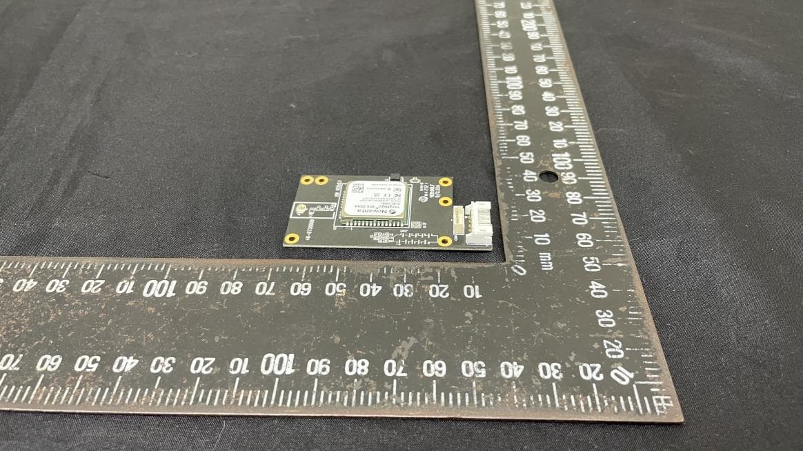
VTV-M7EDEKA
May 13, 2024UHD RFID Module
Equipment Class
DSS - Part 15 Spread Spectrum Transmitter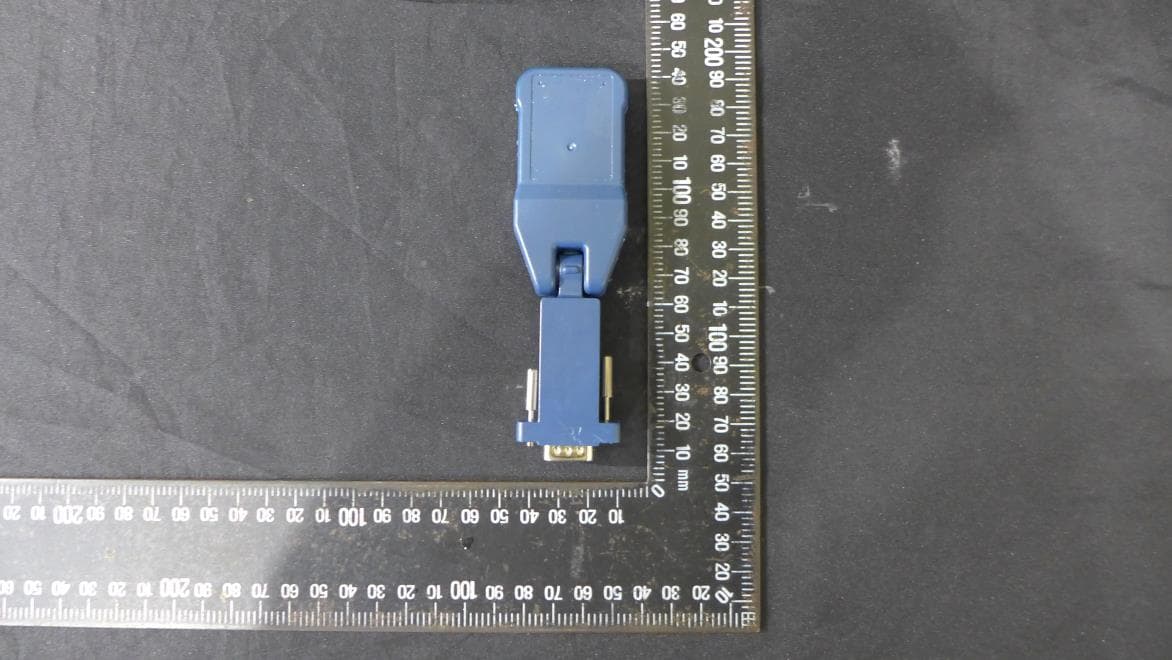
VTV-BA21N
Jan 29, 2023Bluetooth dongle
Equipment Class
DSS - Part 15 Spread Spectrum Transmitter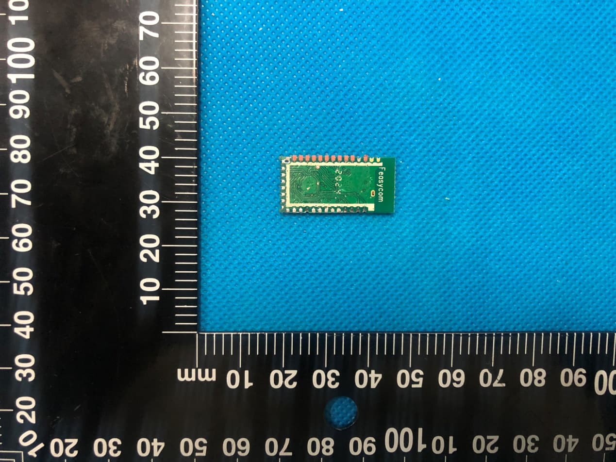
VTV-FSCBT826HC
Dec 24, 2020Bluetooth Module
Equipment Class
DTS - Digital Transmission System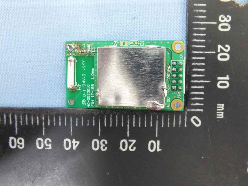
VTV-RFBHS
Feb 04, 2015BT module
Equipment Class
DTS - Digital Transmission System