VU65691SHOW DMX TRANSCEIVER
City Theatrical, LLC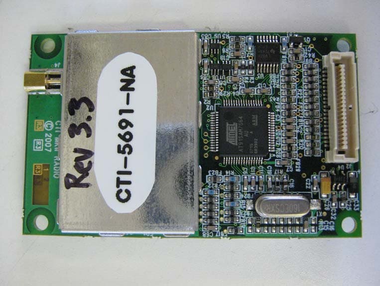
Click to zoom
Application Details
- Equipment Class
- DSS - Part 15 Spread Spectrum Transmitter
- Date of Grant
- Mar 06, 2008
- Application Purpose
- Original Equipment
- Date of Application
- Mar 04, 2008
- Equipment Note
- SHOW DMX TRANSCEIVER
- Frequency Range
- 2406.00000000 - 2476.94000000
- Company
- City Theatrical, LLC
- Country
- United States
Documents & Files
Document Text
Text extracted from the exhibit documents filed with the FCC. Open a document above to read the original.
External Photos
5691 ShoW DMX Radio Transceiver North American Version Component Side 5691 ShoW DMX Radio Transceiver North American Version Solder Side
ID Label/Location Info
5691 FCC Chemical Etch Stencil 100% Scale Dimensions: 1.475” W x .975”H 1-11-08, BWM This device complies with Part 15 of the FCC Rules. Operation is subject to the following two conditions: (1) This device may not cause harmful interference and (2) This device must accept any interference received, including interference that may cause undesired operation. FCC ID : VU65691 IC ID: 7480A-5691 Tested to comply with FCC standards for home or office use. SHoW DMX 5691 PATENT PENDING 5691 FCC Chemical Etch Stencil 400% Scale Dimensions: 1.475” W x .975”H 1-11-08, BWM This device complies with Part 15 of the FCC Rules. Opera- tion is subject to the following two conditions: (1) This device may not cause harmful interference and (2) This device must accept any interference received, including interference that may cause undesired operation. FCC ID : VU65691 IC ID: 7480A-5691 Tested to comply with FCC standards for home or office use. SHoW DMX 5691 PATENT PENDING
Parts List/Tune Up Info
City Theatrical WDS Mark II Transceiver Test Fixture User Manual Rev 1.0 Functional Test Proposal Dec 12, 2007 Prepared by: M. Schneider Pacific Design Engineering 8505 Eastlake Drive Burnaby, BC Canada, V5A 4T7 Tel: 604 421 1311 Fax: 604 421 9202 Pacific Design Engineering Approved by: © 2006, Pacific Design Engineering (1996) Ltd.. All rights reserved. The PDE logo is a Registered Trademark of Pacific Design Engineering (1996) Ltd. This document contains Confidential Information which is Proprietary to PDE. All information disclosed herein is subject to the terms and conditions of the Confidentiality Agreement entered into by the receiving party. No part of this document may be used or reproduced in any form by any means without prior written permission of PDE. Unless otherwise agreed, this document remains the property of PDE and must be returned along with any copies thereof. Rev 1.0 ii Table of Contents 1 Introduction -----------------------------------------------------------------------------------1 1.1 Purpose of Document...........................................................................................1 2 Introduction -----------------------------------------------------------------------------------2 2.1 The Test Fixture ...................................................................................................2 2.2 Special Instructions ..............................................................................................2 3 Installation of Test Fixture Software and Hardware ----------------------------3 3.1 Installing the PCI serial card................................................................................3 3.2 Installing the software..........................................................................................3 3.3 Installing the hardware.........................................................................................3 3.4 Replacing the DAQ modules ...............................................................................3 3.5 Changing the firmware file ..................................................................................4 4 Calibration of Test Fixture ---------------------------------------------------------------5 4.1 Introduction..........................................................................................................5 4.2 Starting the Software............................................................................................5 5 Operation and Use of the Test Fixture-----------------------------------------------6 5.1 Starting the Test Software....................................................................................6 5.2 Board Insertion.....................................................................................................7 5.3 Testing the PCB ...................................................................................................7 Failed Boards ---------------------------------------------------------------------------------- 12 Passed Boards --------------------------------------------------------------------------------- 12 Displaying Results .........................................................................................................13 Rev 1.0 1 1 Introduction 1.1 Purpose of Document The purpose of this Manual is to outline the use of the WDS Mark II PCB Test Fixture (‘Test Fixture’). Rev 1.0 2 2 Introduction 2.1 The Test Fixture The Test Fixture is used for testing the printed circuit boards (PCBs). It is a roughly one foot cube box shaped jig, that clamps the PCB to register it in place with respect to electrical connections connected to the test circuitry located below the board. The test fixture is operated in conjunction with a computer running the test fixture software, to be described below. There are two versions of software; one is for testing product for the North American market, the other, for the European market. Only the North American version is talked about in this manual as the European version’s only difference is the transmitter power is aligned to different values and everything in this manual is applicable to the European version. 2.2 Special Instructions In this document where “press” is written with reference to a button on the computer screen, this can be taken to mean ‘press’ should there be a touch screen monitor displaying the software test program user interface and it can be taken to mean ‘single- click with your mouse’ in case there is no touch screen. Rev 1.0 3 3 Installation of Test Fixture Software and Hardware 3.1 Installing the PCI serial card 1. Please refer to the “SERIAL INSTALLATION GUIDE.pdf” file included on the NI-Serial CD that was included with the serial card. 3.2 Installing the software The following procedure will describe method to install the software application and associated drivers. 1. Insert CD labelled ``WDS MARKII Test Fixture Application Ver 2.1`` 2. Follow directions.................................... 3. Reboot PC 4. Double click the Setup_JLinkARM_V374f.zip included in the Drivers section of the CD and then run the Setup_JLinkARM_V374f.exe application to install the J- Link driver. 5. Run the Install AT91-ISP v1.9.exe included in the Drivers section of the CD. 3.3 Installing the hardware The following procedure will describe the procedure for connecting the test fixture. 1. Plug the power cord into 120VAC mains. 2. Plug the USB cable into a USB2.0 socket on the PC. 3. Plug the serial cable labelled DUT into COM3 of the PCI serial card. 4. Plug the serial cable labelled Golden into COM4 of the PCI serial card. 3.4 Replacing the DAQ modules Inside the test fixture are two USB Data Acquisition (DAQ) modules. They need to be configured as “Golden” and “DUT”. The test fixture will be delivered from PDE pre configured. If at some point the DAQ modules are replaced, the new DAQ modules need to be reconfigured. The following is the procedure to replace the DAQ modules: Note: On…
Text truncated - open the document above for the full version.
Test Report
EMC Compatibilitv Testinq Report Rev.4.0 City Theatricat Inc - #5691ShoW DMX Raclio Tranqceiver - North American Version ciTheatrical lnc. #5691 SHoW DMX Radio Transceiver North American Version Report of Measurements per Industry Canada RSS -210 lssu e 7 Annex 8 and FCC CFR47 Part 15lB; FGC CFR47 PartlSlC - 15.247 Revision 4.0 March 04, 2008 ;*qproved by Checked by Ail ", -/ y Dan Petrulian, EMC Eng. ,r'L! tx,u) b Date Protocol Data Systems Inc, EMC Lab, Abbotsford BC, Canada SCC lSOl17025 (CAN-P4E) Accredited Laboratory No. 612 FCC O.A.T.S. Registration Number 96437 Industry Canada O.A.T.S. Registration Number 1G3384 I TNirepo-rt is tor tGexchlsive usJot protocor Oata Systems CGtonrer anO is proviOeO pursuaniio tC agreement between -l I Protocol and its Customer. Protocol's responsibility and liability are limited to the terms and conditions of the agreement. I ] Protocol assumes no liability to any party, other than to the Customer in accordance with the agreement, for any loss, I I expense or damage occasioned by the use of this report. Only the Customer is authorized to copy or distribute this report I I and then only in its entirety. Any use of the Protocol Data Systems name for the sale or advertisement of the tested material, I i Rroduct or service must first be approved in writing by Protocol Data Systems. The observations and test results in this report j I1 are 1e"!eyq!tl! qdylgl!9_sarngl9,/qle$eq. _ Report Number: A3229 Page 1 of50 EMC Compatibility Testing Report Rev.4.0 City Theatrical Inc - #5691ShoW DMX Radio Transceiver - North American Version Report Number: 03229 Page 2 of 50 Index Section I: Report of Measurements Testing Information ....................................................................3 Section II: Report of Measurements for IC RSS-210 Issue 7 Annex 8 - Emissions Testing ...............6 Part 1 - Unintentional Radiated Emission Testing ..............................................................9 Part 2 - Conducted Emission, AC power lines Testing.....................................................10 Part 3 - Radiated Emissions – Transmit Mode .................................................................11 Part 4 - Conducted Emission Transmit ModeTesting .......................................................13 Part 5 - Frequency Hopping System operating within the 2400 – 2483.5 MHz band ......14 Part 6 - Output Power and EIRP Emissions .....................................................................17 Section III: Report of Measurements for FCC CFR47 Part 15/C........................................................18 Part 1 - Unintentional Radiated Emission Testing ............................................................20 Part 2 - Conducted Emission AC Mains Testing ..............................................................21 Part 3 - Radiated Emissions – Transmit Mode Testing ....................................................22 Part 4 - Conducted Emission Transmit ModeTesting .......................................................24 Part 5 - Antenna Requirement - 15.203............................................................................25 Part 6 - Frequency Hopping Spectrum Operation within the 2400-2483.5 MHz band .....26 Part 7 - Output Power and EIRP Emissions .....................................................................29 Appendix A: Report of Measurements Emission Data and Plots..........................................................30 Appendix B: EUT Photos Unintentional Radiated Emissions Test Set-up............................................49 EUT Photos – AC Conducted Power Line Emissions Test Set-up.............................................................50 EMC Compatibility Testing Report Rev.4.0 City Theatrical Inc - #5691ShoW DMX Radio Transceiver - North American Version Report Number: 03229 Page 3 of 50 Section I: Report of Measurements Testing Information Testing Details TESTED BY: Dan Petrulian TEST CONDITIONS: Temperature and Humidity: October 23, 2007 19°C in, 5.3°C out, 42% October 30, 2007 18°C in, 6.4°C out, 59% December 06, 2007 18°C in, 4.1°C out, 44% December 10, 2007 18 °C in 3.3°C out, 40% February 07, 2008, 21 °C in 6.1°C out, 45% February 08, 2008, 21 °C in 7.5°C out, 45% March 04, 2008, 20 °C in 8.5°C out, 48% TEST VOLTAGE: +5Vdc via Power Supply Anatek 25-2D, delivered for the EUT Equipment. Test Facilities Protocol Data System Inc., Labs 28945 McTavish Rd. Abbotsford BC, Canada, V4X 2E7 SCC ISO/17025 (CAN-P-4E) Accredited Laboratory No. 612 FCC Registration Number 96437 Industry Canada Registration Number IC3384 Test Equipment List EMISSION: ManufacturerModel Equipment Description Serial No. Next Cal HP 85650A CDN Quasi-Peak Adapter 2043A00240 12/09/09 HP 85662A Spectrum Analyzer Display 2318A05184 18/09/09 HP 8566B Spectrum Analyzer RF Section 2241A02102 18/09/09 HP 85685A RF-Preselector 3107A01222 18/09/09 EMCO 3110B Antenna Biconical 20-300MHz 1850 01/12/08 EMCO LPA30 Ant. Log Periodic 200-1000MHz 563 05/12/08 EMCO 3115 Antenna Horn 1-18GHz 9005-3429 06/03/08 SOLAR 8012-50-R-24- BNC LISN(25A 50Ω 50/250μH 10k-50MHz) 863092 28/09/08 Marconi 6960B RF Power Meter 236966/013 12/06/08 Rhientech Custom Antenna Mast N/A N/A Protocol EMC Custom Turntable N/A N/A Measurement Uncertainty Parameter Uncertainty Radio Frequency ±1 x 10⁻⁵ Total RF power, conducted ±1,5 dB RF power density, conducted ±3 dB Spurious emissions, conducted ±3 dB All emissions, radiated ±6 dB Temperature ±1°C Humidity ±5 % DC and low frequency voltages ±3 % Company Under Test NAME: City Theatrical Inc. (Manufacturer of Record) ADDRESS: 475 Barell Avenue Carlstadt, NJ, 07072-2809 CONTACT PERSON: Mr. Lauren E. Dunn EMAIL: [email protected] PHONE NUMBER: 201-549-1161 EMC Compatibility Testing Report Rev.4.0 City Theatrical Inc - #5691ShoW DMX Radio Transceiver - North American Version Report Number: 03229 Page 4 of 50 Company on Test Site NAME: Pacific Design Engineering (Contract Manufacturer) ADDRESS: …
Text truncated - open the document above for the full version.
Contact Information
Applicant
Paul Kleissler(Head of Engineeering)
Test Firm
Protocol LabsRobert Stirling
Technical Specifications
| # | Rule Parts | Frequency Range | Power Output |
|---|---|---|---|
| 1 | 15C | 2.41 GHz - 2.48 GHz | 118.00 mW |
Other Applications from City Theatrical, LLC
VU65792M
Dec 18, 20145792 Modular Radio Transceiver
Equipment Class
DTS - Digital Transmission System
VU65792
Aug 21, 20115792 Modular Radio Transceiver
Equipment Class
DSS - Part 15 Spread Spectrum Transmitter
VU65692
Mar 06, 2008SHOW DMX TRANSCEIVER
Equipment Class
DSS - Part 15 Spread Spectrum Transmitter